SUZUKI GRAND VITARA 1987 Service Manual PDF
Manufacturer: SUZUKI, Model Year: 1987, Model line: GRAND VITARA, Model: SUZUKI GRAND VITARA 1987Pages: 962, PDF Size: 27.87 MB
Page 71 of 962
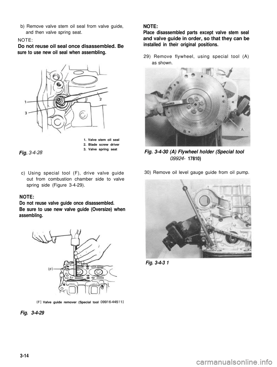
b) Remove valve stem oil seal from valve guide,
and then valve spring seat.
NOTE:
Do not reuse oil seal once disassembled. Besure to use new oil seal when assembling.
1. Valve stem oil seal
2. Blade screw driver
Fig. 3-4-283. Valve spring seat
c) Using special tool (F), drive valve guide out from combustion chamber side to valve
spring side (Figure 3-4-29).
NOTE:
Do not reuse valve guide once disassembled.
Be sure to use new valve guide (Oversize) when
assembling.
NOTE:
Place disassembled parts except valve stem seal
and valve guide in order, so that they can be
installed in their original positions.
29) Remove flywheel, using special tool (A)
as shown.
Fig. 3-4-30 (A) Flywheel holder (Special tool
09924- 17810)
30) Remove oil level gauge guide from oil pump.
Fig. 3-4-3 1 (F)
Valve guide remover (Special tool
09916-44511)
Fig. 3-4-29
3-14
Page 72 of 962
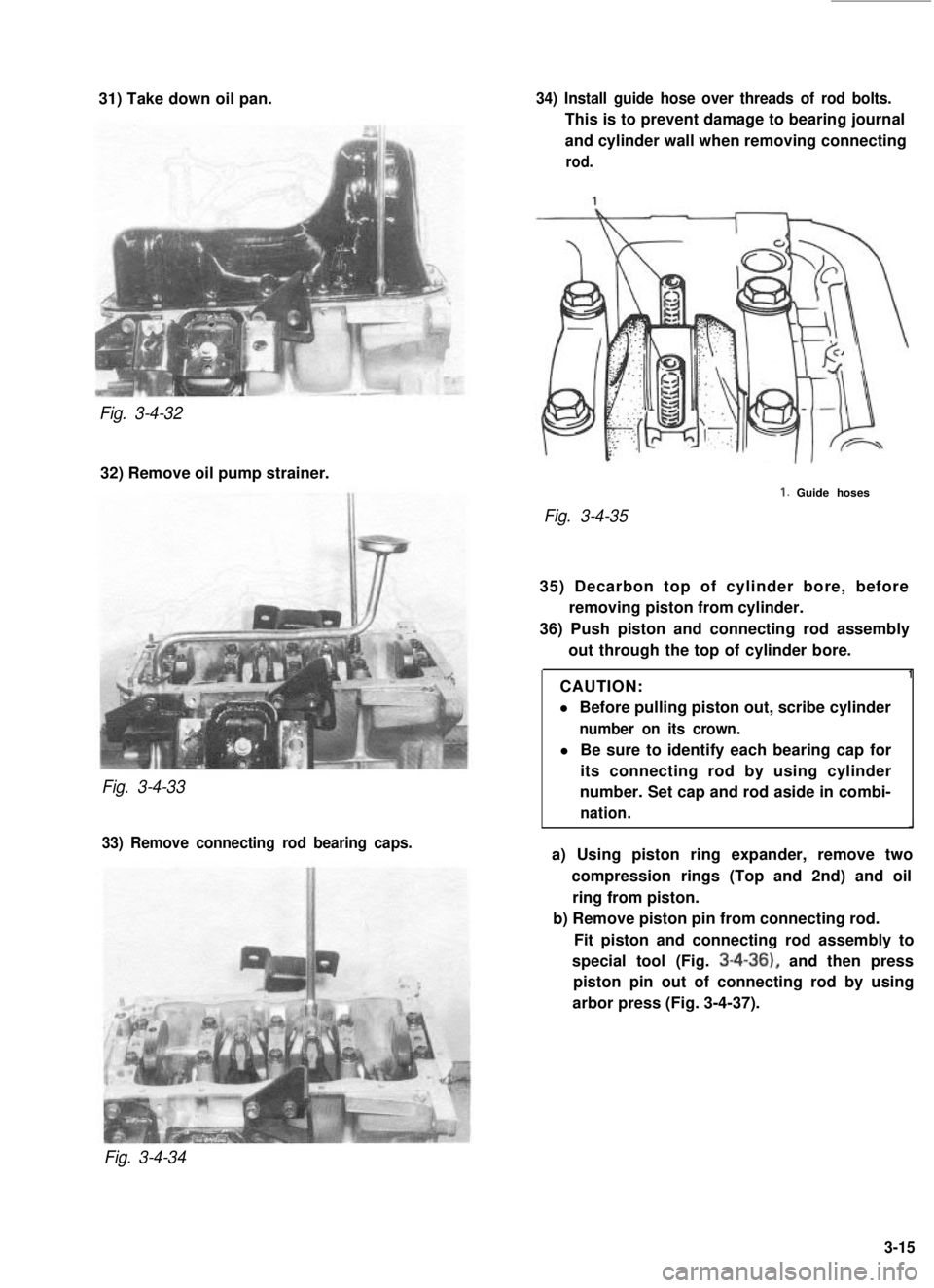
31) Take down oil pan.Fig. 3-4-32
32) Remove oil pump strainer.
Fig. 3-4-33
33) Remove connecting rod bearing caps. 34) Install guide hose over threads of rod bolts.
This is to prevent damage to bearing journal
and cylinder wall when removing connecting
rod.
Fig. 3-4-35
1. Guide hoses
35) Decarbon top of cylinder bore, before removing piston from cylinder.
36) Push piston and connecting rod assembly out through the top of cylinder bore.
CAUTION:
l Before pulling piston out, scribe cylinder
number on its crown.
l Be sure to identify each bearing cap for
its connecting rod by using cylinder
number. Set cap and rod aside in combi-
nation.
1
a) Using piston ring expander, remove two
compression rings (Top and 2nd) and oilring from piston.
b) Remove piston pin from connecting rod.
Fit piston and connecting rod assembly to
special tool (Fig.
3-4-36), and then press
piston pin out of connecting rod by using
arbor press (Fig. 3-4-37).
Fig. 3-4-34
3-15
Page 73 of 962
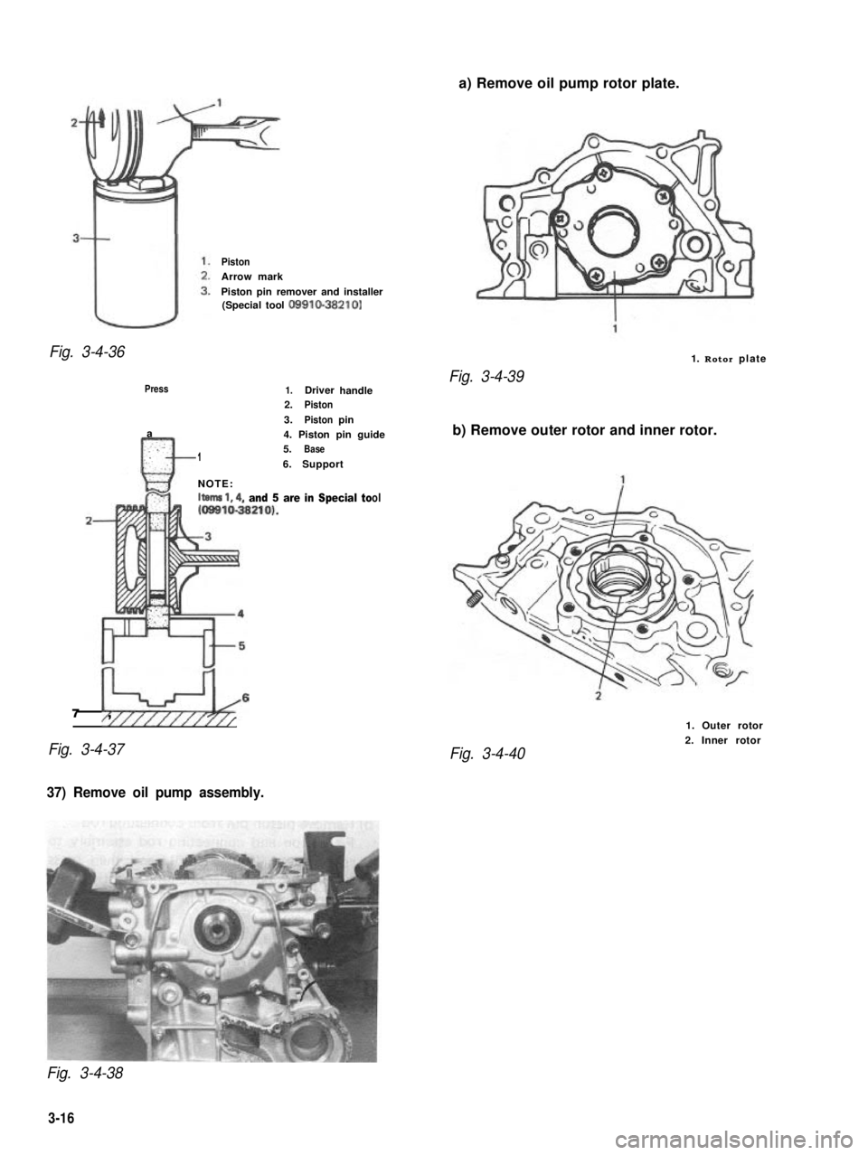
a) Remove oil pump rotor plate.
Piston
Arrow mark
Piston pin remover and installer(Special tool 09910-38210)
Fig. 3-4-361. Rotor plate
Press
a.:n:..:: ,.1
1.Driverhandle2.Piston
3.Pistonpin
4. Piston pin guide5.Base
6.Support
NOTE:Itema 1,4, and 5 are in Special to ol1 (09810-38210).
I+4-b67 ,////I /
Fig. 3-4-37
Fig. 3-4-39
b) Remove outer rotor and inner rotor.
Fig. 3-4-40
1. Outer rotor
2. Inner rotor
37) Remove oil pump assembly.
Fig. 3-4-38
3-16
Page 74 of 962
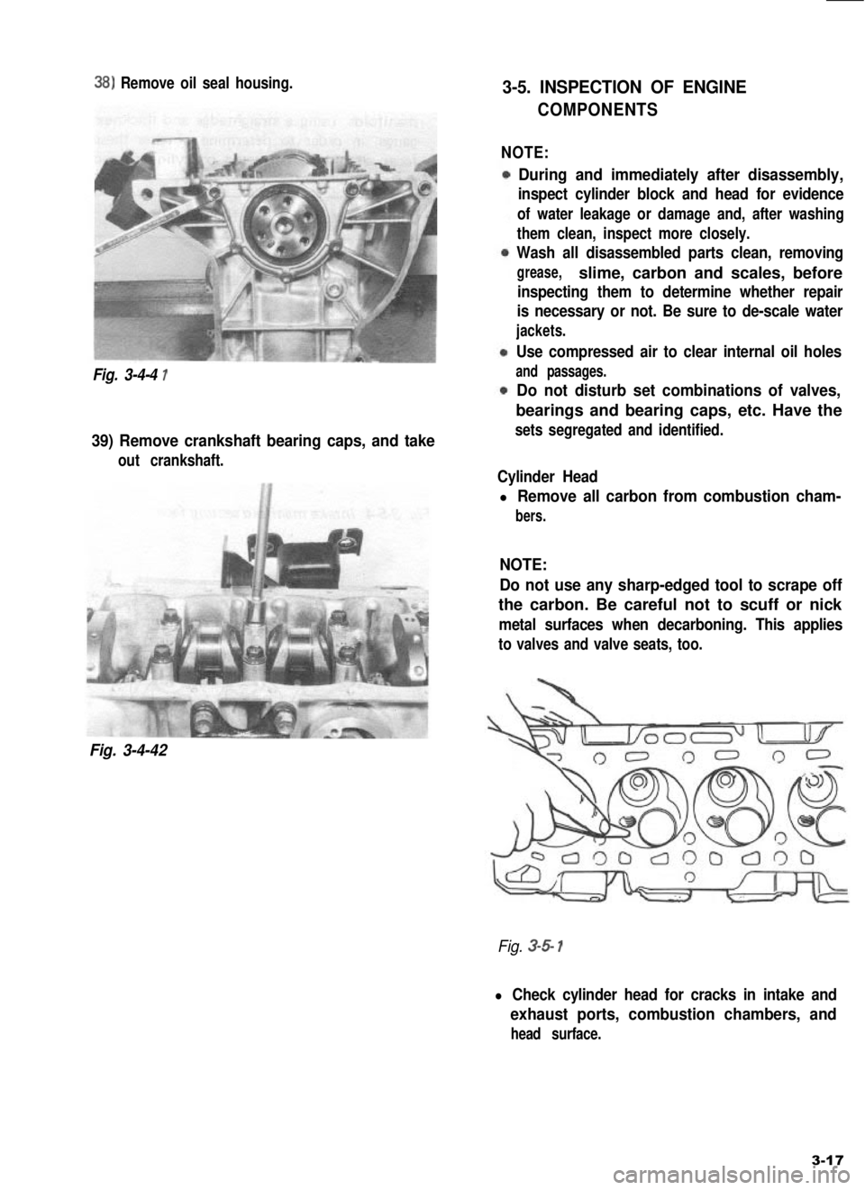
38) Remove oil seal housing.
Fig. 3-4-4 1
39) Remove crankshaft bearing caps, and take
out crankshaft.
Fig. 3-4-42
3-5. INSPECTION OF ENGINE
COMPONENTS
NOTE:
During and immediately after disassembly,
inspect cylinder block and head for evidence
of water leakage or damage and, after washing
them clean, inspect more closely.
Wash all disassembled parts clean, removing
grease,slime, carbon and scales, before
inspecting them to determine whether repair
is necessary or not. Be sure to de-scale water
jackets.
Use compressed air to clear internal oil holes
and passages.
Do not disturb set combinations of valves,
bearings and bearing caps, etc. Have the
sets segregated and identified.
Cylinder Head
l Remove all carbon from combustion cham-
bers.
NOTE:
Do not use any sharp-edged tool to scrape off
the carbon. Be careful not to scuff or nick
metal surfaces when decarboning. This applies
to valves and valve seats, too.
Fig. 3-5 1
l Check cylinder head for cracks in intake and
exhaust ports, combustion chambers, and
head surface.
3-17
Page 75 of 962
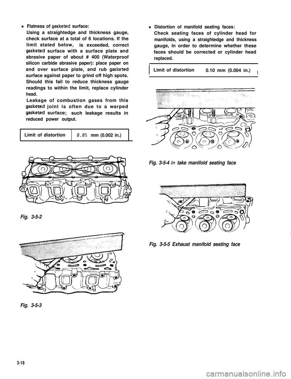
l Flatness of gasketed surface:
Using a straightedge and thickness gauge,
check surface at a total of 6 locations. If the
limit stated below,is exceeded, correct
gasketed surface with a surface plate and
abrasive paper of about # 400 (Waterproof
silicon carbide abrasive paper): place paper on
and over surface plate, and rub gasketed
surface against paper to grind off high spots.
Should this fail to reduce thickness gauge
readings to within the limit, replace cylinder
head.
Leakage of combustion gases from this
gasketed joint is often due to a warped
gasketed surface;such leakage results in
reduced power output.
l Distortion of manifold seating faces:
Check seating faces of cylinder head for
manifolds, using a straightedge and thickness
gauge, in order to determine whether these
faces should be corrected or cylinder head
replaced.
ILimit of distortion0.10 mm (0.004 in.)I
Limit of distortion0.05 mm (0.002 in.)
Fig. 3-5-4 In take manifold seating face
Fig. 3-5-2
Fig. 3-5-5 Exhaust manifold seating face
Fig. 3-5-3
3-18
Page 76 of 962
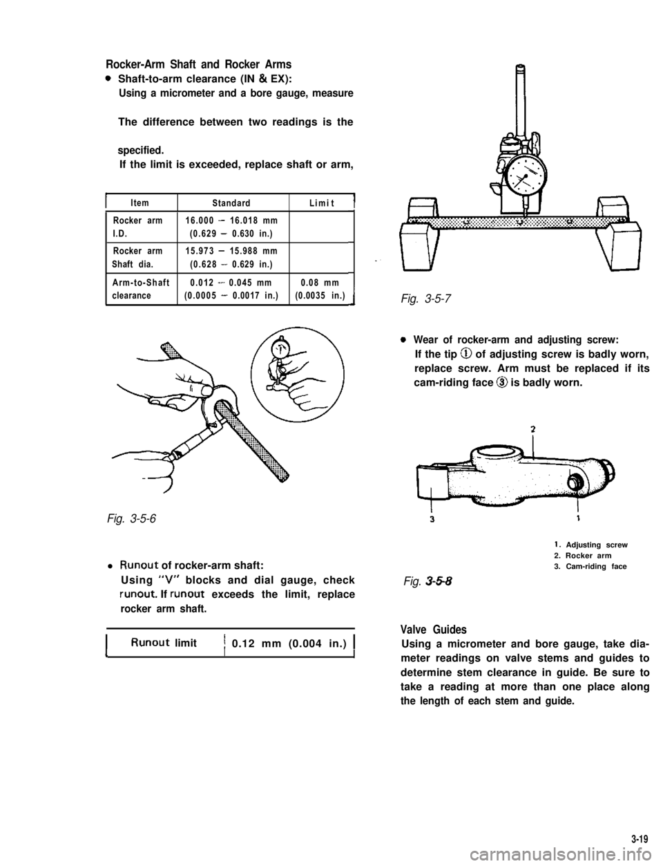
Rocker-Arm Shaft and Rocker Arms
0Shaft-to-arm clearance (IN & EX):
Using a micrometer and a bore gauge, measure
The difference between two readings is the
specified.
If the limit is exceeded, replace shaft or arm,
IItemStandardLimitI
Rocker arm16.000 - 16.018 mm
I.D.(0.629 - 0.630 in.)
Rocker arm15.973 - 15.988 mm
Shaft dia.(0.628 - 0.629 in.)
Arm-to-Shaft0.012 - 0.045 mm0.08 mm
clearance(0.0005 - 0.0017 in.)(0.0035 in.)
Fig. 3-5-6
l Runout of rocker-arm shaft:
Using “V” blocks and dial gauge, check
runout. If runout exceeds the limit, replace
rocker arm shaft.
IRunout limitI1 0.12 mm (0.004 in.) 1II
Fig. 3-5-7
0Wear of rocker-arm and adjusting screw:
If the tip @ of adjusting screw is badly worn,
replace screw. Arm must be replaced if its
cam-riding face @I is badly worn.
1. Adjusting screw2. Rocker arm3. Cam-riding face
Fig. 3-5-8
Valve Guides
Using a micrometer and bore gauge, take dia-
meter readings on valve stems and guides to
determine stem clearance in guide. Be sure to
take a reading at more than one place along
the length of each stem and guide.
3-19
Page 77 of 962
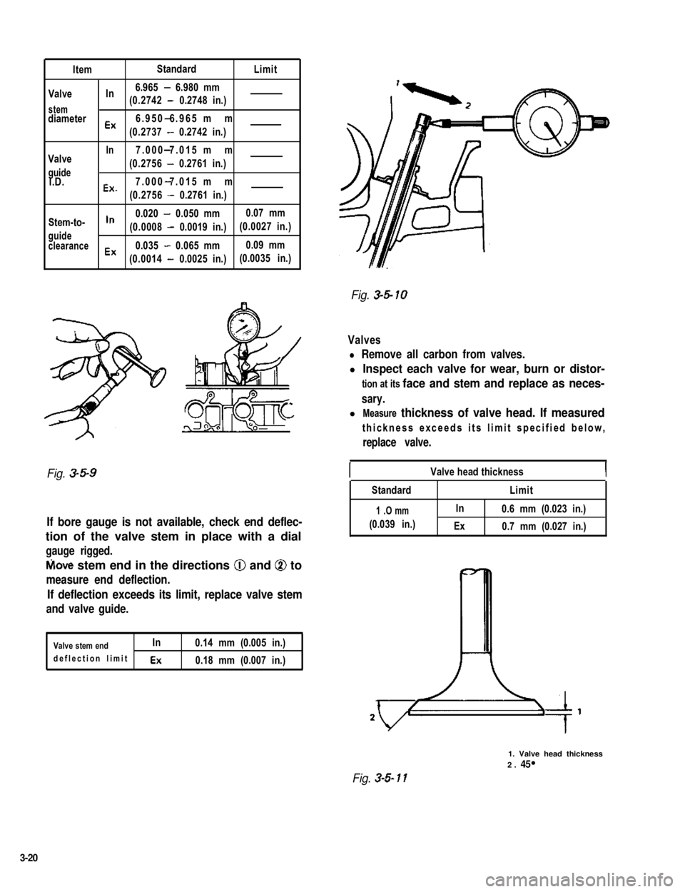
ItemStandardLimit
In6.965 - 6.980 mmValve(0.2742 - 0.2748 in.)stemdiameter-Ex6.950 6.965 mm
(0.2737 - 0.2742 in.)
Valve
guideI.D.
-In7.000 7.015 mm
(0.2756 - 0.2761 in.)
7.000 7.015 mm-
Ex’(0.2756 - 0.2761 in.)
Stem-to-In0.020 - 0.050 mm0.07 mm
guide(0.0008 - 0.0019 in.)(0.0027 in.)
clearanceEx0.035 - 0.065 mm0.09 mm
(0.0014 - 0.0025 in.)(0.0035 in.)
Fig. 34 10
Valves
l Remove all carbon from valves.
l Inspect each valve for wear, burn or distor-
tion at its face and stem and replace as neces-
sary.
l Measure thickness of valve head. If measured
thickness exceeds its limit specified below,
replace valve.
Fig. 3-5-9IValve head thicknessI
If bore gauge is not available, check end deflec-
tion of the valve stem in place with a dial
gauge rigged.
fvlove stem end in the directions @ and @ to
measure end deflection.
If deflection exceeds its limit, replace valve stem
and valve guide.
Valve stem endIn
deflection limit Ex
0.14 mm (0.005 in.)
0.18 mm (0.007 in.)
Standard
1 .O mm
(0.039 in.)
Limit
In0.6 mm (0.023 in.)
Ex0.7 mm (0.027 in.)
Fig. 3-S 11
1. Valve head thickness2. 45
3-20
Page 78 of 962
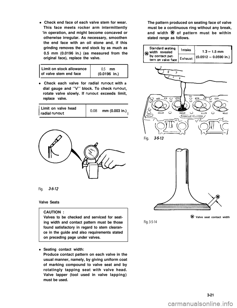
l Check end face of each valve stem for wear.
This face meets rocker arm intermittently
‘in operation, and might become concaved or
otherwise irregular. As necessary, smoothen
the end face with an oil stone and, if this
grinding removes the end stock by as much as
0.5 mm (0.0196 in.) (as measured from the
original face), replace the valve.
Limit on stock allowance0.5 mm
of valve stem end face(0.0196 in.)
l Check each valve for radial runout with a
dial gauge and “V” block. To check runout,
rotate valve slowly. If runout exceeds limit,
replace valve.
I
Limit on valve head
radial runout0.08 mm (0.003 in.)I
Fig. 3-612
Valve Seats
CAUTION :
Valves to be checked and serviced for seat-
ing width and contact pattern must be those
found satisfactory in regard to stem clearan-
ce in the guide and also requirements stated
on preceding page under valves.
l Seating contact width:
Produce contact pattern on each valve in the
usual manner, namely, by giving uniform coat
of marking compound to valve seat and by
rotatingly tapping seat with valve head.
Valve lapper (tool used in valve lapping)
must be used.
The pattern produced on seating face of valve
must be a continuous ring without any break,
and width 6@ of pattern must be within
stated range as follows.
width revealed1.3- 1.5 mm
(0.0512 - 0.0590 in.)
Fig. 3-5-13
Fig. 3-5-14
@ Valve seat contact width
3-21
Page 79 of 962
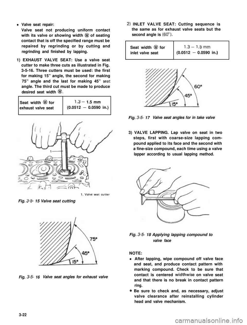
l Valve seat repair:
Valve seat not producing uniform contact
with its valve or showing width @ of seating
contact that is off the specified range must be
repaired by regrinding or by cutting and
regrinding and finished by lapping.
1) EXHAUST VALVE SEAT: Use a valve seat
cutter to make three cuts as illustrated in Fig.
3-5-16. Three cutters must be used: the first
for making 15” angle, the second for making
75” angle and the last for making 45” Seat
angle. The third cut must be made to produce
desired seat width @I!).
Seat width @ for1.3- 1.5 mm
exhaust valve seat(0.0512 - 0.0590 in.)
1. Valve seat CUtter
Fig. 3-S 15 Valve seat cutting
Fig. 3-5- 16Valve seat angles for exhaust valve
2) INLET VALVE SEAT: Cutting sequence is
the same as for exhaust valve seats but the
second angle is (60” ).
Seat width @I for1.3- 1.5mm
inlet valve seatI(0.0512 - 0.0590 in.)
Fig. 3-5- 17Valve seat angles for in take valve
3) VALVE LAPPING. Lap valve on seat in two
steps, first with coarse-size lapping com-
pound applied to its face and the second with
a fine-size compound, each time using a valve
lapper according to usual lapping method.
Fig. 3-5- 18 Applying lapping compound to
valve face
NOTE:
l After lapping, wipe compound off valve face
and seat, and produce contact pattern with
marking compound. Check to be sure that
contact is centered widthwise on valve seat
and that there is no break in contact pattern
ring.
a Be sure to check and, as necessary, adjust
valve clearance after reinstalling cylinder
head and valve mechanism.
3-22
Page 80 of 962
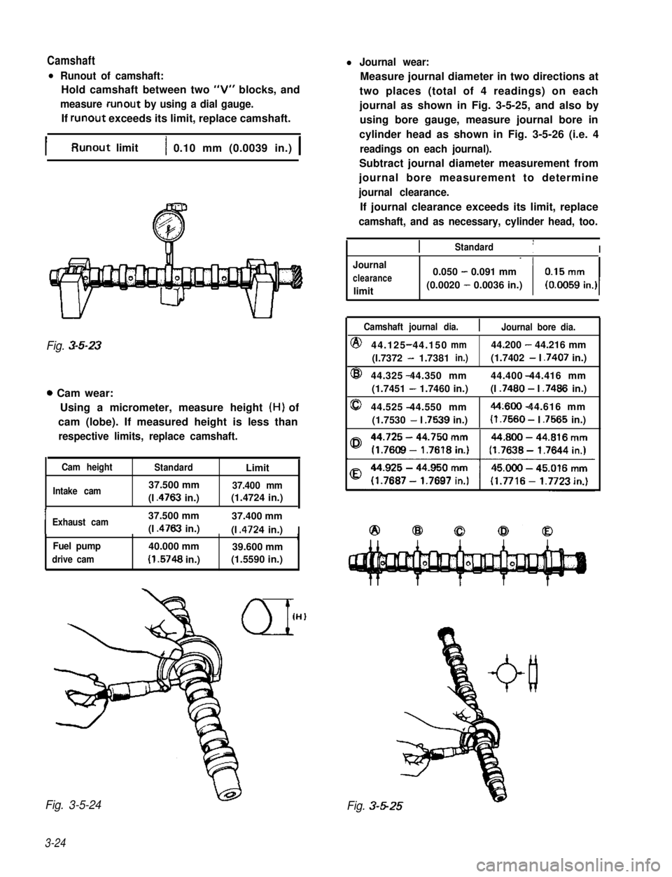
Camshaftl Journal wear:
l Runout of camshaft:
Hold camshaft between two “V” blocks, and
measure runout by using a dial gauge.
If runout exceeds its limit, replace camshaft.
Measure journal diameter in two directions at
two places (total of 4 readings) on each
journal as shown in Fig. 3-5-25, and also by
using bore gauge, measure journal bore in
cylinder head as shown in Fig. 3-5-26 (i.e. 4
readings on each journal).
Subtract journal diameter measurement from
journal bore measurement to determine
journal clearance.
If journal clearance exceeds its limit, replace
camshaft, and as necessary, cylinder head, too.
IRunout limit1 0.10 mm (0.0039 in.) 1
Fig. 3-5-23
0 Cam wear:
Using a micrometer, measure height (H) of
cam (lobe). If measured height is less than
respective limits, replace camshaft.
Cam heightStandardLimit
Intake cam37.500 mm37.400 mm
(I .4763 in.)(1.4724 in.),
IExhaust cam37.500 mm37.400 mm
(I .4763 in.)(I .4724 in.)IrFuel pump40.000 mm39.600 mm
drive cam(I .5748 in.)(1.5590 in.)
Fig. 3-5-24
3-24
IIStandard1I
Journal
clearance
limit
0.050 - 0.091 mm
(0.0020 - 0.0036 in.)
Camshaft journal dia.Journal bore dia.
@44.125 44.150-mm44.200 - 44.216 mm
(I.7372 - 1.7381in.)(1.7402 - I .7407 in.)
@44.325 44.350 mm- 44.400 44.416 mm
(1.7451 - 1.7460 in.)(I .7480 - I .7486 in.)
044.525 44.550 mm-44~600 44.616 mm-
(1.7530 - I .7539 in.)(I .7560 - I .7565 in.)
Fig. 3-5-25