SUZUKI SWIFT 2000 1.G Transmission Service Workshop Manual
Manufacturer: SUZUKI, Model Year: 2000, Model line: SWIFT, Model: SUZUKI SWIFT 2000 1.GPages: 447, PDF Size: 10.54 MB
Page 201 of 447
TRANSFER 7D-3
ON-VEHICLE SERVICE
OIL CHANGE
1) Before changing or inspecting oil, be sure to stop engine and
lift vehicle horizontally.
2) With vehicle lifted up, check oil level and leakage. If leakage
exists, correct or repair it.
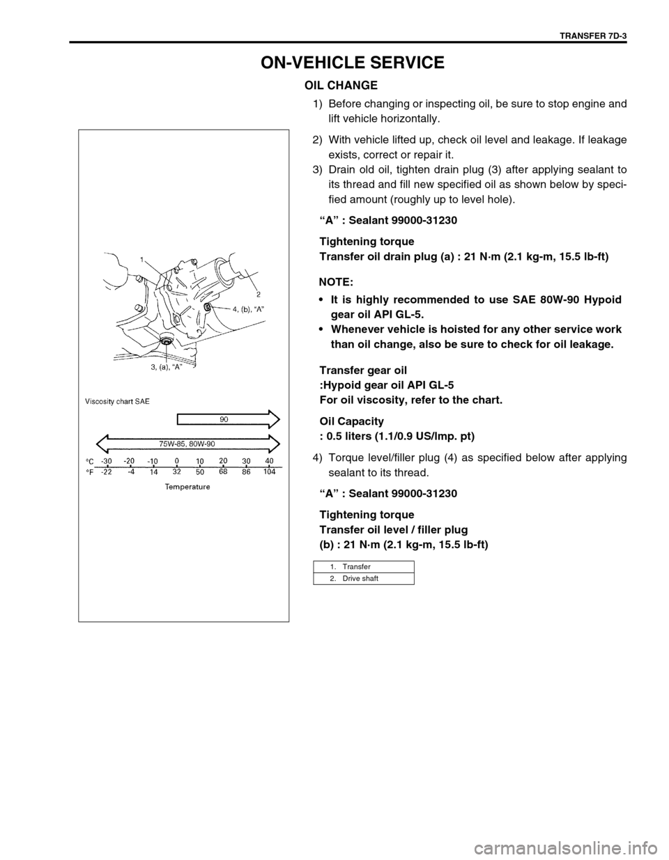
3) Drain old oil, tighten drain plug (3) after applying sealant to
its thread and fill new specified oil as shown below by speci-
fied amount (roughly up to level hole).
“A” : Sealant 99000-31230
Tightening torque
Transfer oil drain plug (a) : 21 N·m (2.1 kg-m, 15.5 lb-ft)
Transfer gear oil
:Hypoid gear oil API GL-5
For oil viscosity, refer to the chart.
Oil Capacity
: 0.5 liters (1.1/0.9 US/lmp. pt)
4) Torque level/filler plug (4) as specified below after applying
sealant to its thread.
“A” : Sealant 99000-31230
Tightening torque
Transfer oil level / filler plug
(b) : 21 N·m (2.1 kg-m, 15.5 lb-ft) NOTE:
It is highly recommended to use SAE 80W-90 Hypoid
gear oil API GL-5.
Whenever vehicle is hoisted for any other service work
than oil change, also be sure to check for oil leakage.
1. Transfer
2. Drive shaft
Page 202 of 447
7D-4 TRANSFER
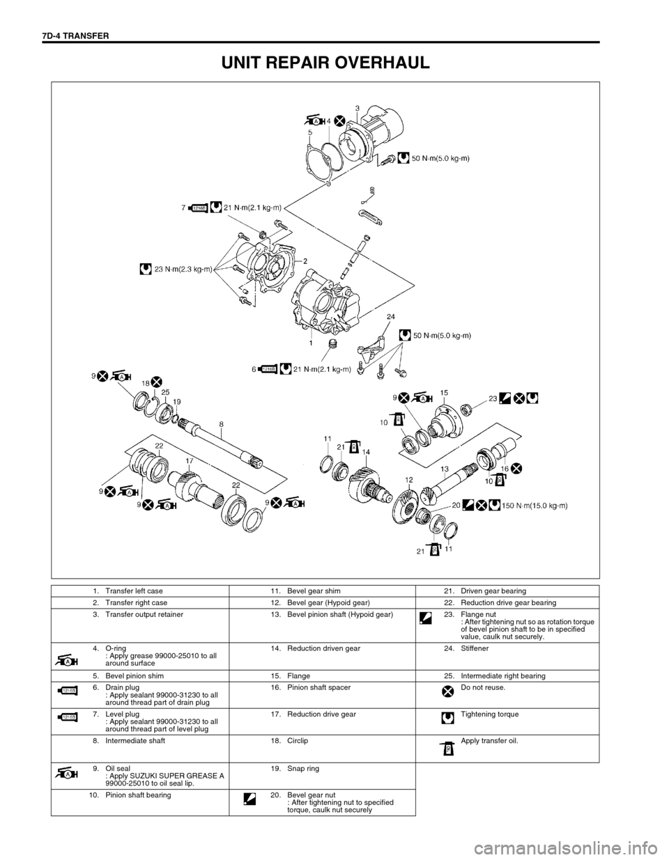
UNIT REPAIR OVERHAUL
1. Transfer left case 11. Bevel gear shim 21. Driven gear bearing
2. Transfer right case 12. Bevel gear (Hypoid gear) 22. Reduction drive gear bearing
3. Transfer output retainer 13. Bevel pinion shaft (Hypoid gear) 23. Flange nut
: After tightening nut so as rotation torque
of bevel pinion shaft to be in specified
value, caulk nut securely.
4. O-ring
: Apply grease 99000-25010 to all
around surface14. Reduction driven gear 24. Stiffener
5. Bevel pinion shim 15. Flange 25. Intermediate right bearing
6. Drain plug
: Apply sealant 99000-31230 to all
around thread part of drain plug16. Pinion shaft spacer Do not reuse.
7. Level plug
: Apply sealant 99000-31230 to all
around thread part of level plug17. Reduction drive gear Tightening torque
8. Intermediate shaft 18. Circlip Apply transfer oil.
9. Oil seal
: Apply SUZUKI SUPER GREASE A
99000-25010 to oil seal lip.19. Snap ring
10. Pinion shaft bearing 20. Bevel gear nut
: After tightening nut to specified
torque, caulk nut securely
Page 203 of 447
TRANSFER 7D-5
UNIT DISMOUNTING
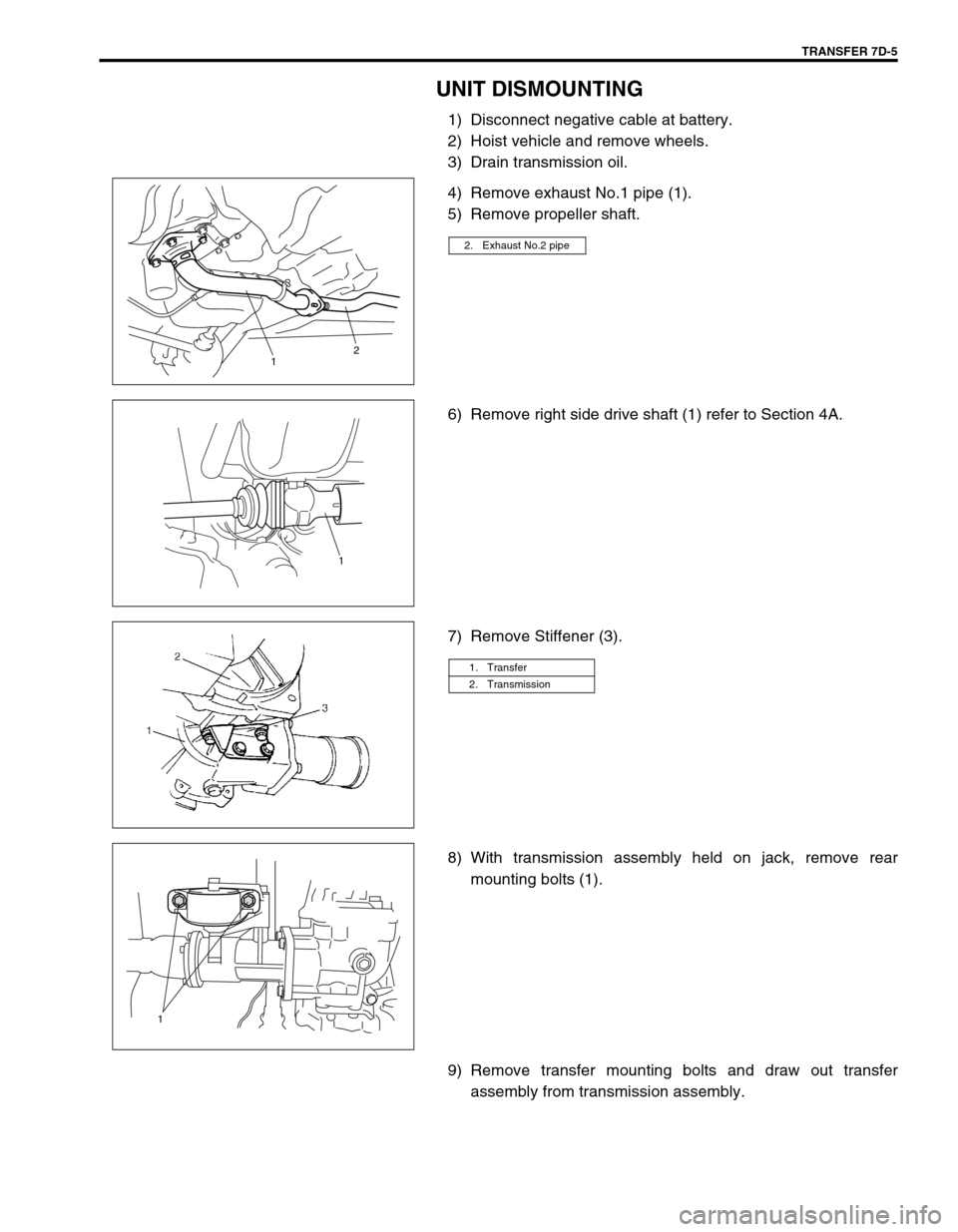
1) Disconnect negative cable at battery.
2) Hoist vehicle and remove wheels.
3) Drain transmission oil.
4) Remove exhaust No.1 pipe (1).
5) Remove propeller shaft.
6) Remove right side drive shaft (1) refer to Section 4A.
7) Remove Stiffener (3).
8) With transmission assembly held on jack, remove rear
mounting bolts (1).
9) Remove transfer mounting bolts and draw out transfer
assembly from transmission assembly.
2. Exhaust No.2 pipe
12
1
1. Transfer
2. Transmission
1
Page 204 of 447
7D-6 TRANSFER
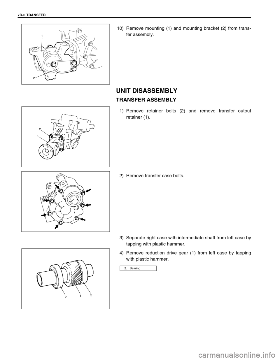
10) Remove mounting (1) and mounting bracket (2) from trans-
fer assembly.
UNIT DISASSEMBLY
TRANSFER ASSEMBLY
1) Remove retainer bolts (2) and remove transfer output
retainer (1).
2) Remove transfer case bolts.
3) Separate right case with intermediate shaft from left case by
tapping with plastic hammer.
4) Remove reduction drive gear (1) from left case by tapping
with plastic hammer.
1
2
2. Bearing
Page 205 of 447
TRANSFER 7D-7
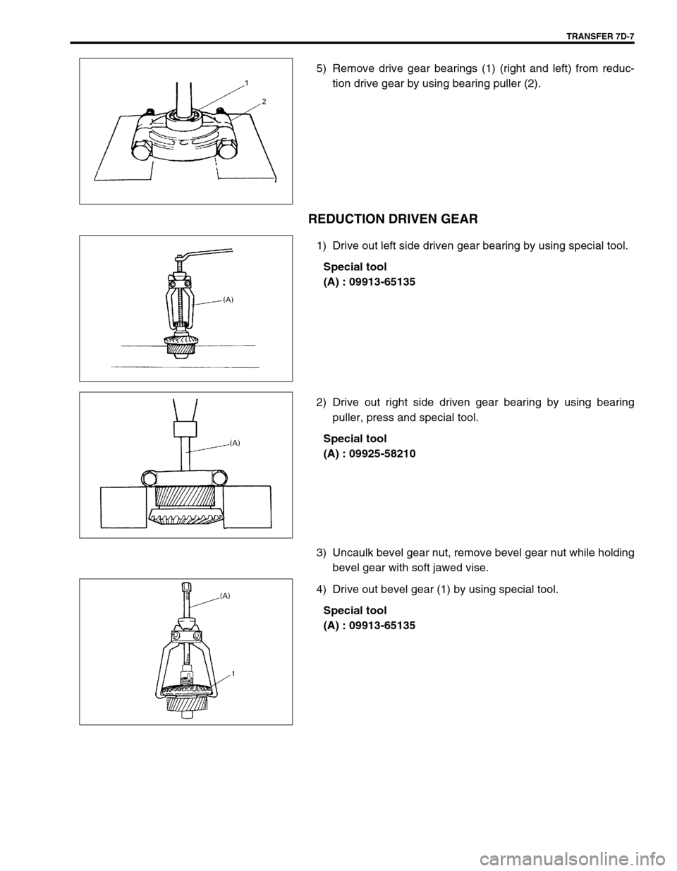
5) Remove drive gear bearings (1) (right and left) from reduc-
tion drive gear by using bearing puller (2).
REDUCTION DRIVEN GEAR
1) Drive out left side driven gear bearing by using special tool.
Special tool
(A) : 09913-65135
2) Drive out right side driven gear bearing by using bearing
puller, press and special tool.
Special tool
(A) : 09925-58210
3) Uncaulk bevel gear nut, remove bevel gear nut while holding
bevel gear with soft jawed vise.
4) Drive out bevel gear (1) by using special tool.
Special tool
(A) : 09913-65135
Page 206 of 447
7D-8 TRANSFER
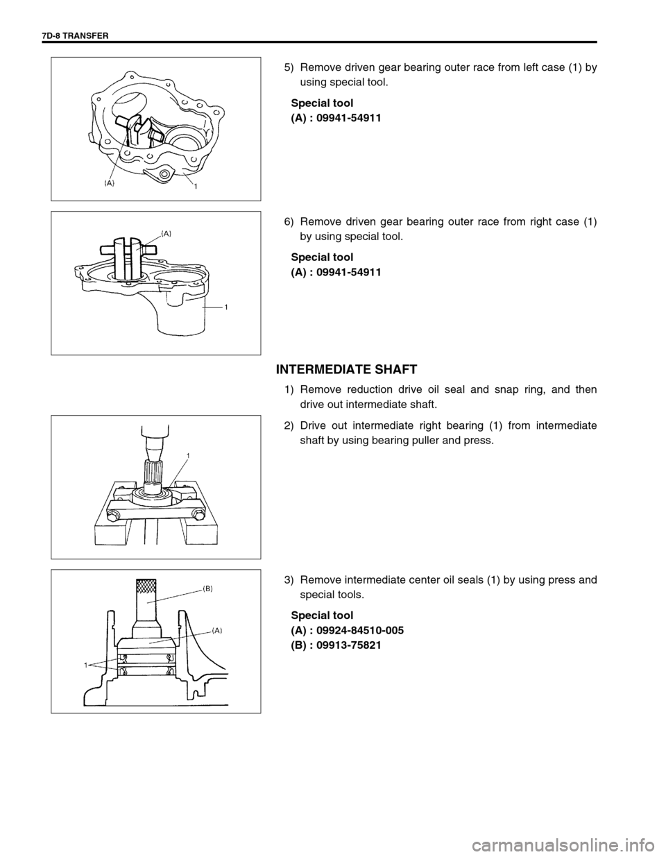
5) Remove driven gear bearing outer race from left case (1) by
using special tool.
Special tool
(A) : 09941-54911
6) Remove driven gear bearing outer race from right case (1)
by using special tool.
Special tool
(A) : 09941-54911
INTERMEDIATE SHAFT
1) Remove reduction drive oil seal and snap ring, and then
drive out intermediate shaft.
2) Drive out intermediate right bearing (1) from intermediate
shaft by using bearing puller and press.
3) Remove intermediate center oil seals (1) by using press and
special tools.
Special tool
(A) : 09924-84510-005
(B) : 09913-75821
Page 207 of 447
TRANSFER 7D-9
TRANSFER OUTPUT RETAINER
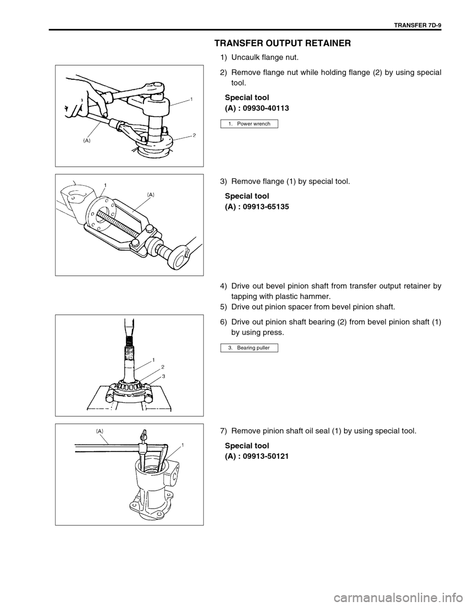
1) Uncaulk flange nut.
2) Remove flange nut while holding flange (2) by using special
tool.
Special tool
(A) : 09930-40113
3) Remove flange (1) by special tool.
Special tool
(A) : 09913-65135
4) Drive out bevel pinion shaft from transfer output retainer by
tapping with plastic hammer.
5) Drive out pinion spacer from bevel pinion shaft.
6) Drive out pinion shaft bearing (2) from bevel pinion shaft (1)
by using press.
7) Remove pinion shaft oil seal (1) by using special tool.
Special tool
(A) : 09913-50121
1. Power wrench
3. Bearing puller
Page 208 of 447
7D-10 TRANSFER
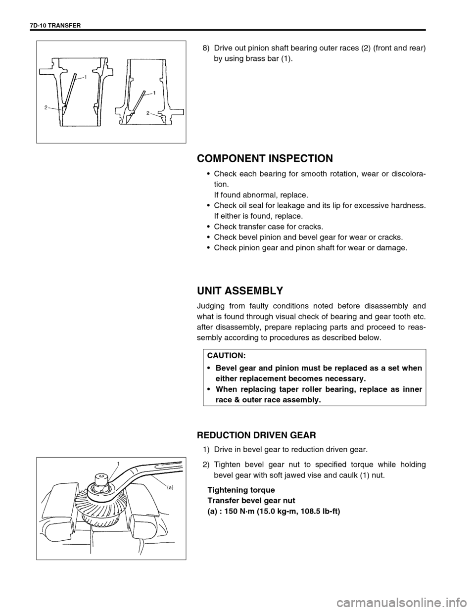
8) Drive out pinion shaft bearing outer races (2) (front and rear)
by using brass bar (1).
COMPONENT INSPECTION
Check each bearing for smooth rotation, wear or discolora-
tion.
If found abnormal, replace.
Check oil seal for leakage and its lip for excessive hardness.
If either is found, replace.
Check transfer case for cracks.
Check bevel pinion and bevel gear for wear or cracks.
Check pinion gear and pinon shaft for wear or damage.
UNIT ASSEMBLY
Judging from faulty conditions noted before disassembly and
what is found through visual check of bearing and gear tooth etc.
after disassembly, prepare replacing parts and proceed to reas-
sembly according to procedures as described below.
REDUCTION DRIVEN GEAR
1) Drive in bevel gear to reduction driven gear.
2) Tighten bevel gear nut to specified torque while holding
bevel gear with soft jawed vise and caulk (1) nut.
Tightening torque
Transfer bevel gear nut
(a) : 150 N·m (15.0 kg-m, 108.5 lb-ft)
CAUTION:
Bevel gear and pinion must be replaced as a set when
either replacement becomes necessary.
When replacing taper roller bearing, replace as inner
race & outer race assembly.
Page 209 of 447
TRANSFER 7D-11
BEVEL GEAR SHIM
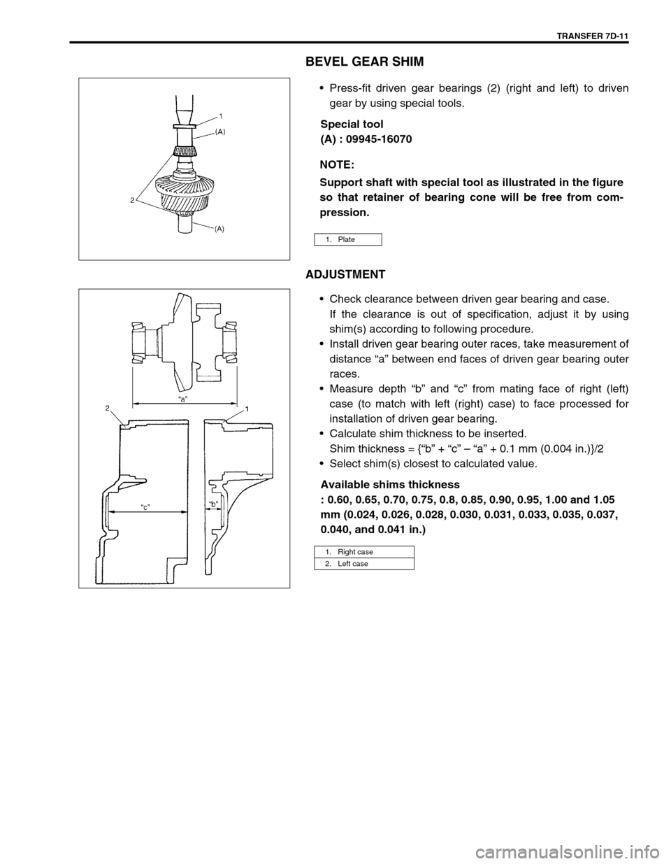
Press-fit driven gear bearings (2) (right and left) to driven
gear by using special tools.
Special tool
(A) : 09945-16070
ADJUSTMENT
Check clearance between driven gear bearing and case.
If the clearance is out of specification, adjust it by using
shim(s) according to following procedure.
Install driven gear bearing outer races, take measurement of
distance “a” between end faces of driven gear bearing outer
races.
Measure depth “b” and “c” from mating face of right (left)
case (to match with left (right) case) to face processed for
installation of driven gear bearing.
Calculate shim thickness to be inserted.
Shim thickness = {“b” + “c” – “a” + 0.1 mm (0.004 in.)}/2
Select shim(s) closest to calculated value.
Available shims thickness
: 0.60, 0.65, 0.70, 0.75, 0.8, 0.85, 0.90, 0.95, 1.00 and 1.05
mm (0.024, 0.026, 0.028, 0.030, 0.031, 0.033, 0.035, 0.037,
0.040, and 0.041 in.) NOTE:
Support shaft with special tool as illustrated in the figure
so that retainer of bearing cone will be free from com-
pression.
1. Plate
1. Right case
2. Left case
Page 210 of 447
7D-12 TRANSFER
TRANSFER OUTPUT RETAINER
ADJUSTMENT
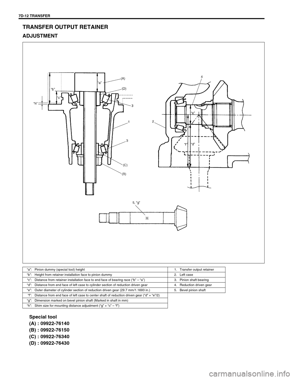
Special tool
(A) : 09922-76140
(B) : 09922-76150
(C) : 09922-76340
(D) : 09922-76430
“a”: Pinion dummy (special tool) height 1. Transfer output retainer
“b”: Height from retainer installation face to pinion dummy 2. Left case
“c”: Distance from retainer installation face to end face of bearing race (“b” – “a”) 3. Pinion shaft bearing
“d”: Distance from end face of left case to cylinder section of reduction driven gear 4. Reduction driven gear
“e”: Outer diameter of cylinder section of reduction driven gear (29.7 mm/1.1693 in.) 5. Bevel pinion shaft
“f”: Distance from end face of left case to center shaft of reduction driven gear (“d” + “e”/2)
“g”: Dimension marked on bevel pinion shaft (Marked in shaft in mm)
“h”: Shim size for mounting distance adjustment (“g” + “c” – “f”)