TOYOTA CAMRY V20 1986 Service Information
Manufacturer: TOYOTA, Model Year: 1986, Model line: CAMRY V20, Model: TOYOTA CAMRY V20 1986Pages: 2389, PDF Size: 84.44 MB
Page 431 of 2389
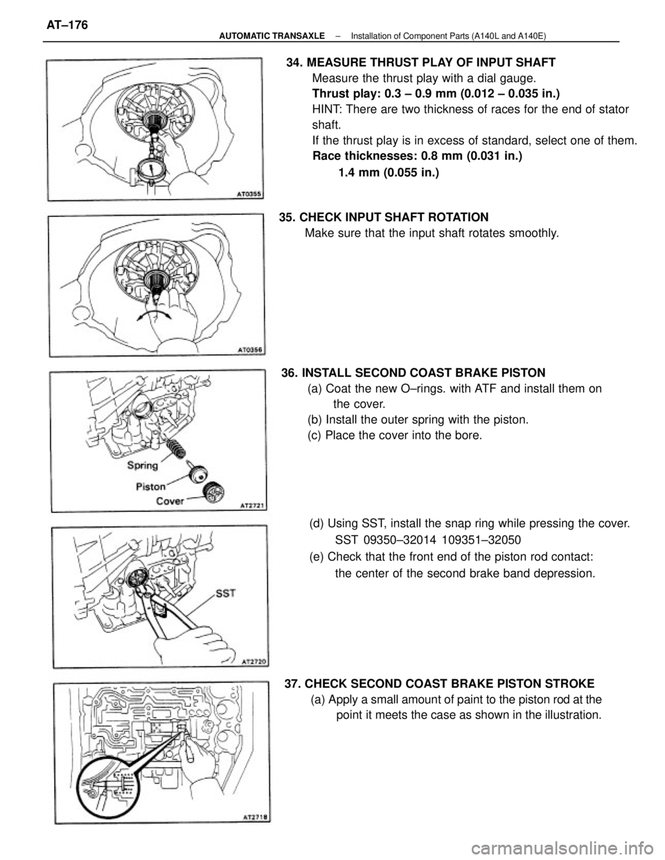
34. MEASURE THRUST PLAY OF INPUT SHAFT
Measure the thrust play with a dial gauge.
Thrust play: 0.3 ± 0.9 mm (0.012 ± 0.035 in.)
HINT: There are two thickness of races for the end of stator
shaft.
If the thrust play is in excess of standard, select one of them.
Race thicknesses: 0.8 mm (0.031 in.)
1.4 mm (0.055 in.)
36. INSTALL SECOND COAST BRAKE PISTON
(a) Coat the new O±rings. with ATF and install them on
the cover.
(b) Install the outer spring with the piston.
(c) Place the cover into the bore.
(d) Using SST, install the snap ring while pressing the cover.
SST 09350±32014 109351±32050
(e) Check that the front end of the piston rod contact:
the center of the second brake band depression.
37. CHECK SECOND COAST BRAKE PISTON STROKE
(a) Apply a small amount of paint to the piston rod at the
point it meets the case as shown in the illustration. 35. CHECK INPUT SHAFT ROTATION
Make sure that the input shaft rotates smoothly.
± AUTOMATIC TRANSAXLEInstallation of Component Parts (A140L and A140E)AT±176
Page 432 of 2389
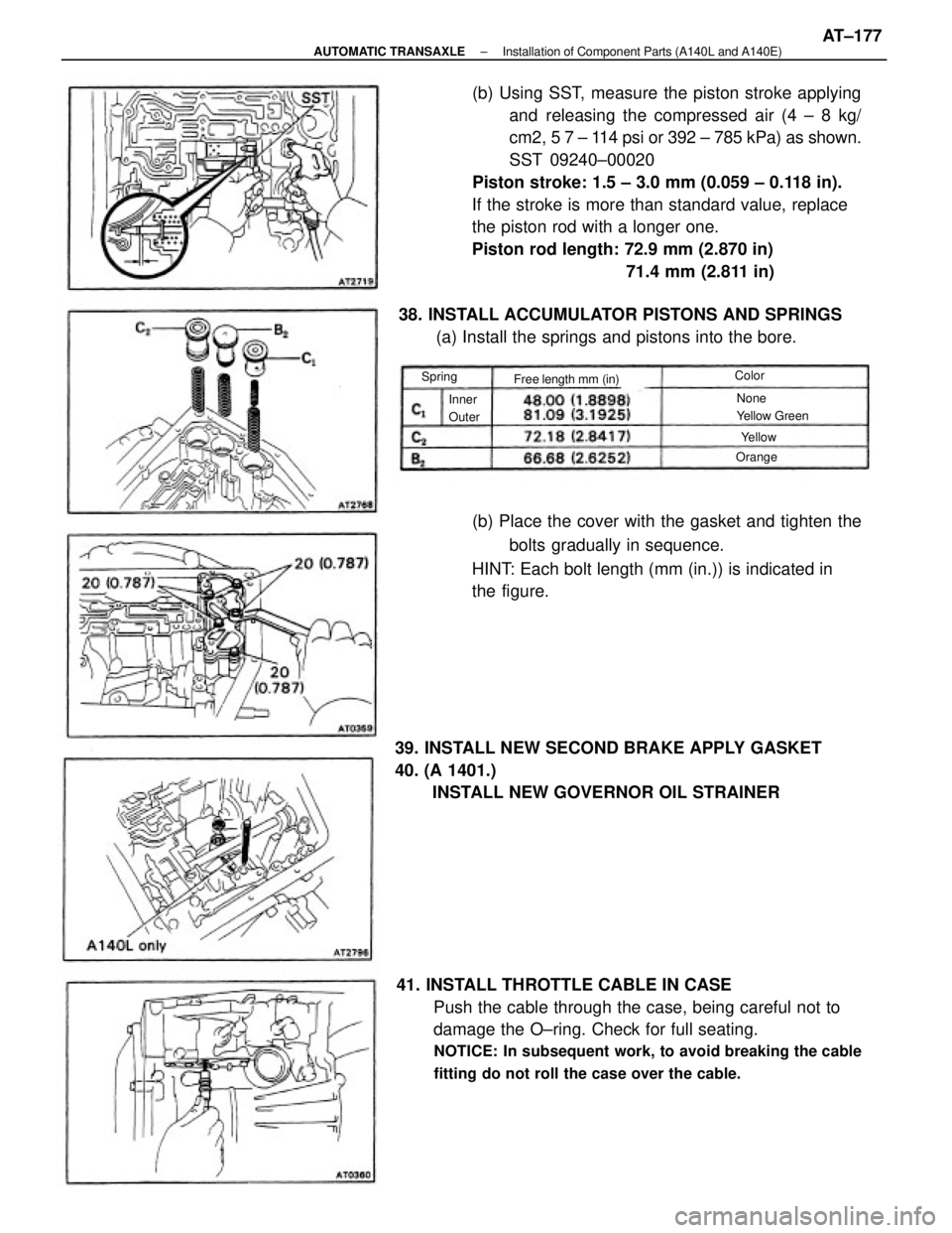
(b) Using SST, measure the piston stroke applying
and releasing the compressed air (4 ± 8 kg/
cm2, 5 7 ± 114 psi or 392 ± 785 kPa) as shown.
SST 09240±00020
Piston stroke: 1.5 ± 3.0 mm (0.059 ± 0.118 in).
If the stroke is more than standard value, replace
the piston rod with a longer one.
Piston rod length: 72.9 mm (2.870 in)
71.4 mm (2.811 in)
41. INSTALL THROTTLE CABLE IN CASE
Push the cable through the case, being careful not to
damage the O±ring. Check for full seating.
NOTICE: In subsequent work, to avoid breaking the cable
fitting do not roll the case over the cable.
(b) Place the cover with the gasket and tighten the
bolts gradually in sequence.
HINT: Each bolt length (mm (in.)) is indicated in
the figure.
39. INSTALL NEW SECOND BRAKE APPLY GASKET
40. (A 1401.)
INSTALL NEW GOVERNOR OIL STRAINER 38. INSTALL ACCUMULATOR PISTONS AND SPRINGS
(a) Install the springs and pistons into the bore.
Free length mm (in)
None
Yellow Green Inner
Outer
Orange Spring
Yellow Color
± AUTOMATIC TRANSAXLEInstallation of Component Parts (A140L and A140E)AT±177
Page 433 of 2389
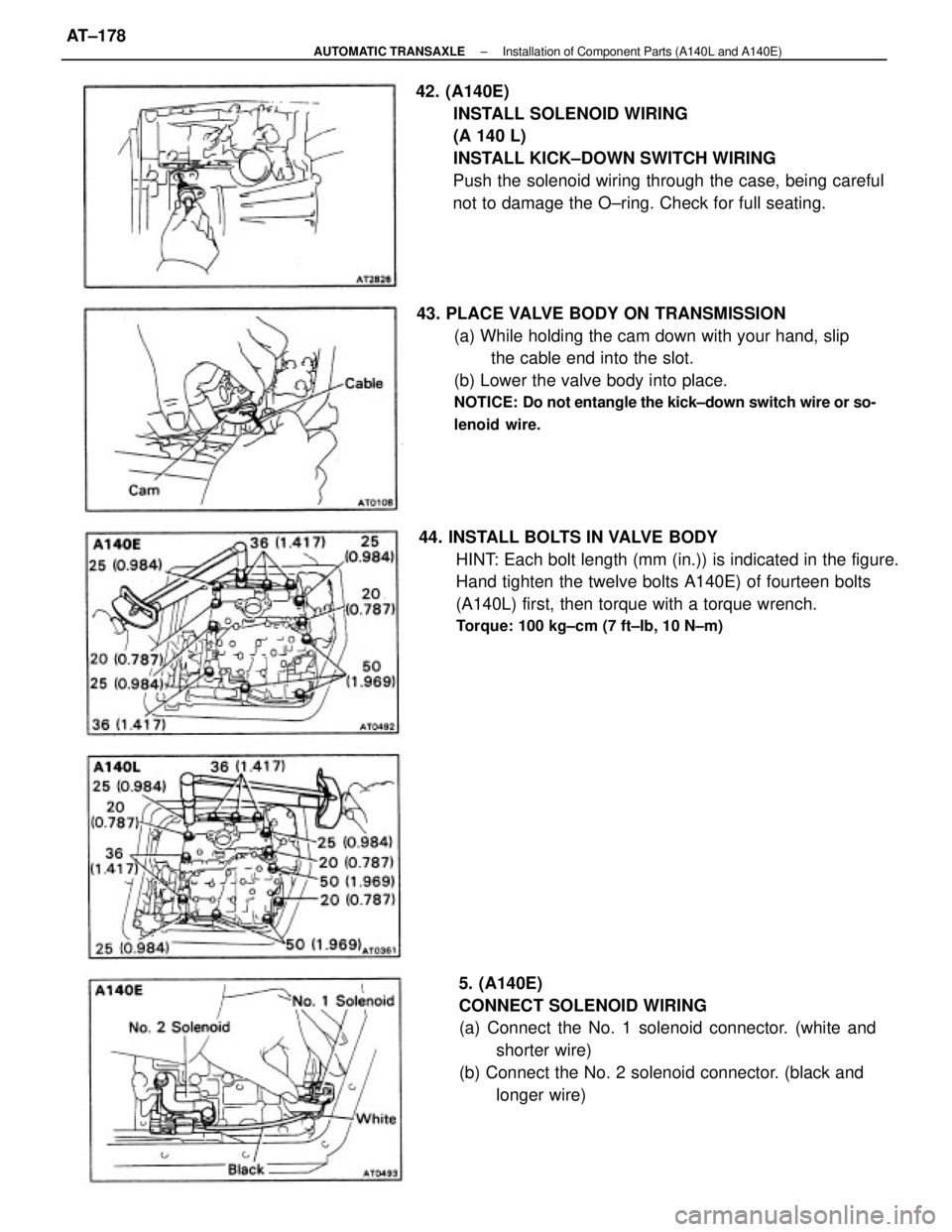
42. (A140E)
INSTALL SOLENOID WIRING
(A 140 L)
INSTALL KICK±DOWN SWITCH WIRING
Push the solenoid wiring through the case, being careful
not to damage the O±ring. Check for full seating.
44. INSTALL BOLTS IN VALVE BODY
HINT: Each bolt length (mm (in.)) is indicated in the figure.
Hand tighten the twelve bolts A140E) of fourteen bolts
(A140L) first, then torque with a torque wrench.
Torque: 100 kg±cm (7 ft±Ib, 10 N±m)
43. PLACE VALVE BODY ON TRANSMISSION
(a) While holding the cam down with your hand, slip
the cable end into the slot.
(b) Lower the valve body into place.
NOTICE: Do not entangle the kick±down switch wire or so-
lenoid wire.
5. (A140E)
CONNECT SOLENOID WIRING
(a) Connect the No. 1 solenoid connector. (white and
shorter wire)
(b) Connect the No. 2 solenoid connector. (black and
longer wire)
± AUTOMATIC TRANSAXLEInstallation of Component Parts (A140L and A140E)AT±178
Page 434 of 2389
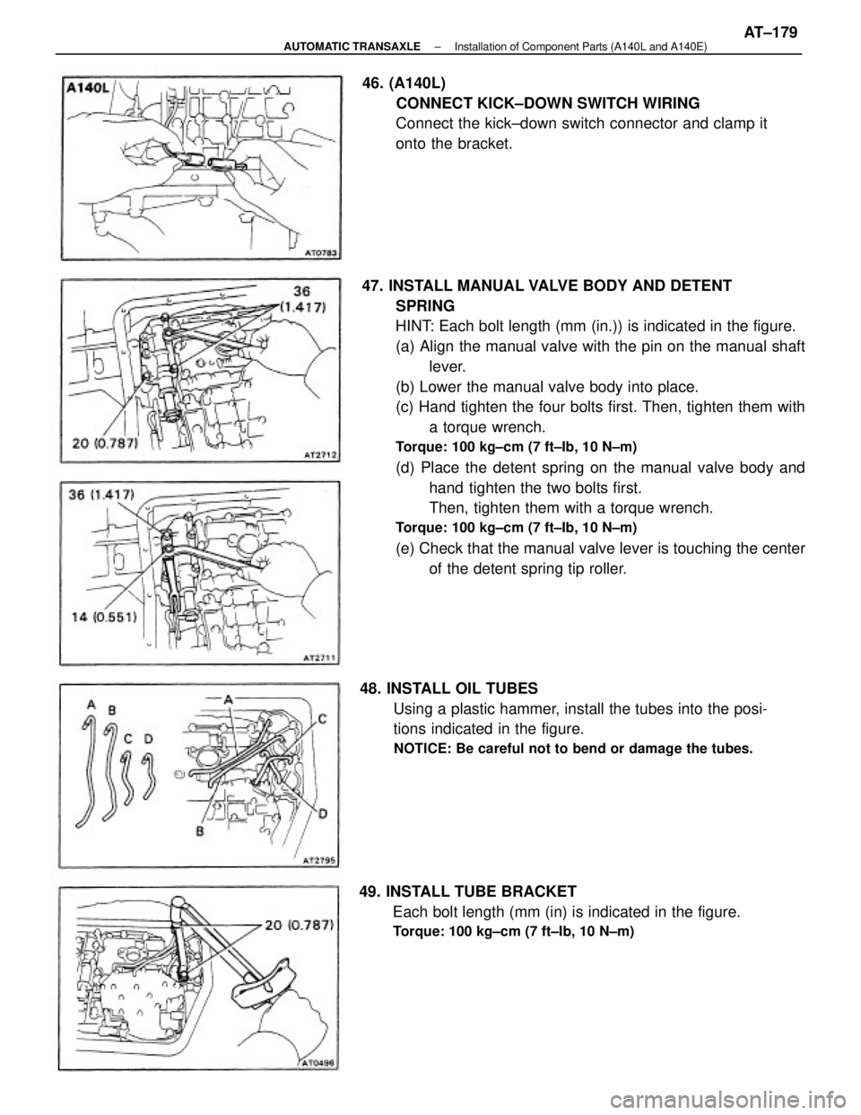
47. INSTALL MANUAL VALVE BODY AND DETENT
SPRING
HINT: Each bolt length (mm (in.)) is indicated in the figure.
(a) Align the manual valve with the pin on the manual shaft
lever.
(b) Lower the manual valve body into place.
(c) Hand tighten the four bolts first. Then, tighten them with
a torque wrench.
Torque: 100 kg±cm (7 ft±Ib, 10 N±m)
(d) Place the detent spring on the manual valve body and
hand tighten the two bolts first.
Then, tighten them with a torque wrench.
Torque: 100 kg±cm (7 ft±Ib, 10 N±m)
(e) Check that the manual valve lever is touching the center
of the detent spring tip roller.
48. INSTALL OIL TUBES
Using a plastic hammer, install the tubes into the posi-
tions indicated in the figure.
NOTICE: Be careful not to bend or damage the tubes.
46. (A140L)
CONNECT KICK±DOWN SWITCH WIRING
Connect the kick±down switch connector and clamp it
onto the bracket.
49. INSTALL TUBE BRACKET
Each bolt length (mm (in) is indicated in the figure.
Torque: 100 kg±cm (7 ft±Ib, 10 N±m)
± AUTOMATIC TRANSAXLEInstallation of Component Parts (A140L and A140E)AT±179
Page 435 of 2389
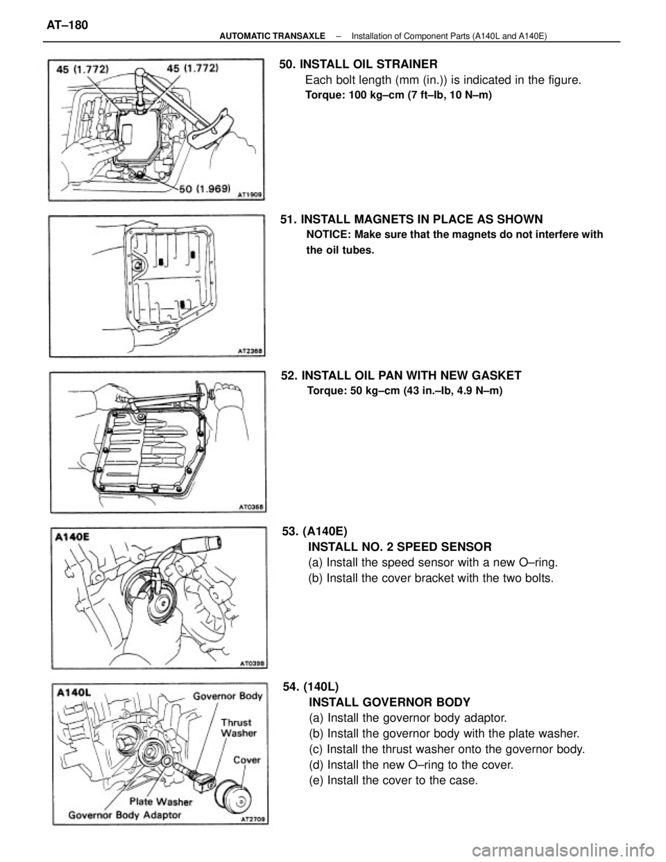
54. (140L)
INSTALL GOVERNOR BODY
(a) Install the governor body adaptor.
(b) Install the governor body with the plate washer.
(c) Install the thrust washer onto the governor body.
(d) Install the new O±ring to the cover.
(e) Install the cover to the case. 53. (A140E)
INSTALL NO. 2 SPEED SENSOR
(a) Install the speed sensor with a new O±ring.
(b) Install the cover bracket with the two bolts. 50. INSTALL OIL STRAINER
Each bolt length (mm (in.)) is indicated in the figure.
Torque: 100 kg±cm (7 ft±Ib, 10 N±m)
51. INSTALL MAGNETS IN PLACE AS SHOWN
NOTICE: Make sure that the magnets do not interfere with
the oil tubes.
52. INSTALL OIL PAN WITH NEW GASKET
Torque: 50 kg±cm (43 in.±Ib, 4.9 N±m)
± AUTOMATIC TRANSAXLEInstallation of Component Parts (A140L and A140E)AT±180
Page 436 of 2389
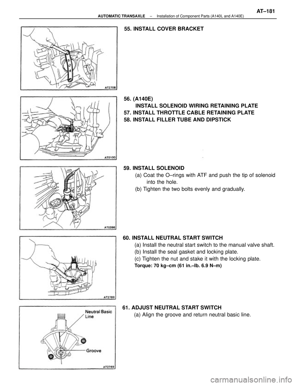
60. INSTALL NEUTRAL START SWITCH
(a) Install the neutral start switch to the manual valve shaft.
(b) Install the seal gasket and locking plate.
(c) Tighten the nut and stake it with the locking plate.
Torque: 70 kg±cm (61 in.±Ib. 6.9 N±m)
56. (A140E)
INSTALL SOLENOID WIRING RETAINING PLATE
57. INSTALL THROTTLE CABLE RETAINING PLATE
58. INSTALL FILLER TUBE AND DIPSTICK
59. INSTALL SOLENOID
(a) Coat the O±rings with ATF and push the tip of solenoid
into the hole.
(b) Tighten the two bolts evenly and gradually.
61. ADJUST NEUTRAL START SWITCH
(a) Align the groove and return neutral basic line. 55. INSTALL COVER BRACKET
± AUTOMATIC TRANSAXLEInstallation of Component Parts (A140L and A140E)AT±181
Page 437 of 2389
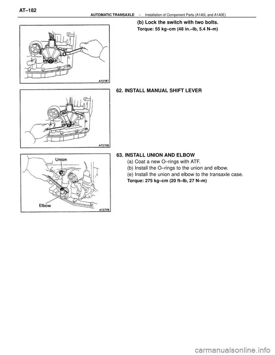
63. INSTALL UNION AND ELBOW
(a) Coat a new O±rings with ATF.
(b) Install the O±rings to the union and elbow.
(e) Install the union and elbow to the transaxle case.
Torque: 275 kg±cm (20 ft±Ib, 27 N±m)
(b) Lock the switch with two bolts.
Torque: 55 kg±cm (48 in.±Ib, 5.4 N±m)
62. INSTALL MANUAL SHIFT LEVER
± AUTOMATIC TRANSAXLEInstallation of Component Parts (A140L and A140E)AT±182
Page 438 of 2389
A540E AND A540H
AUTOMATIC TRANSAXLE
AUTOMATIC TRANSAXLEAT±183
Page 439 of 2389
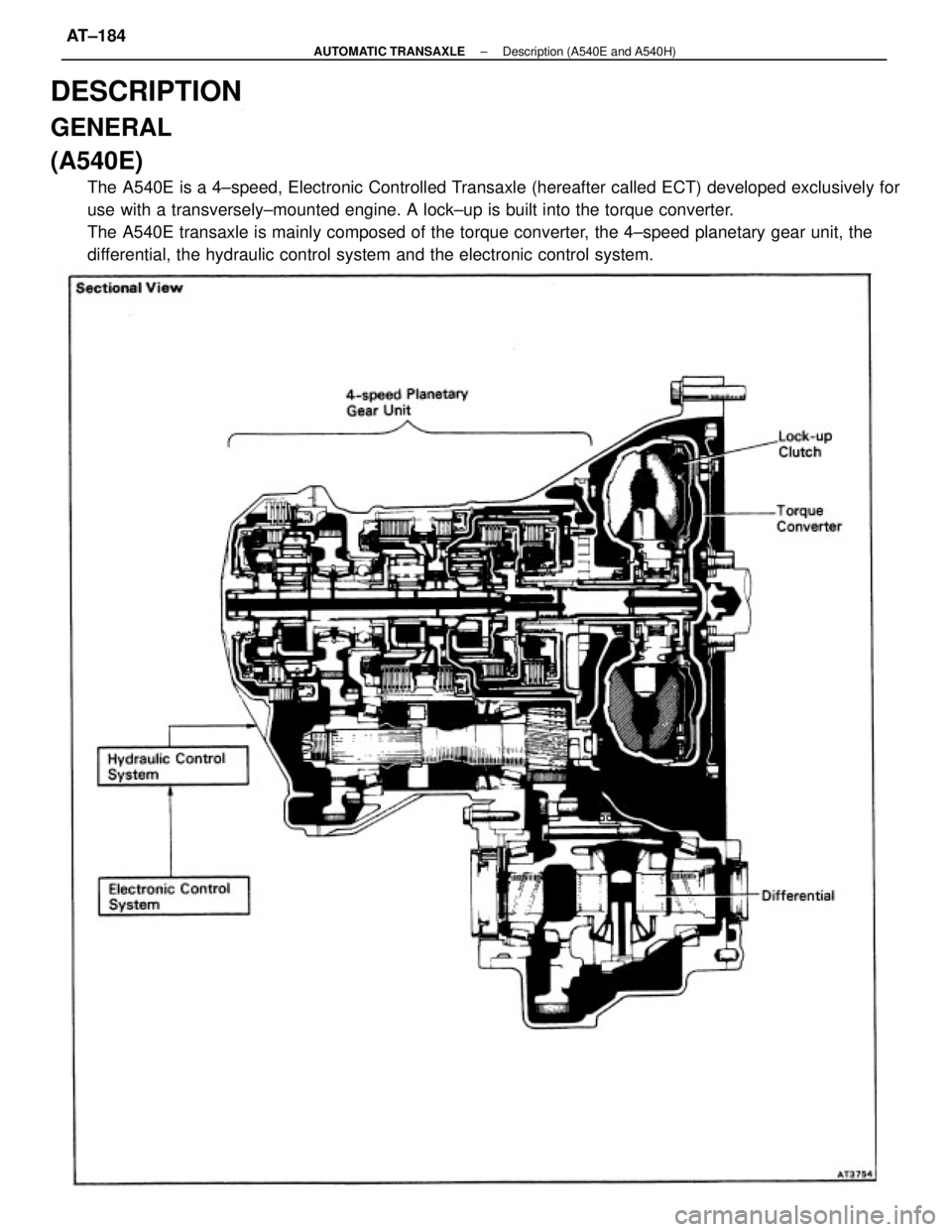
DESCRIPTION
GENERAL
(A540E)
The A540E is a 4±speed, Electronic Controlled Transaxle (hereafter called ECT) developed exclusively for
use with a transversely±mounted engine. A lock±up is built into the torque converter.
The A540E transaxle is mainly composed of the torque converter, the 4±speed planetary gear unit, the
differential, the hydraulic control system and the electronic control system.
± AUTOMATIC TRANSAXLEDescription (A540E and A540H)AT±184
Page 440 of 2389
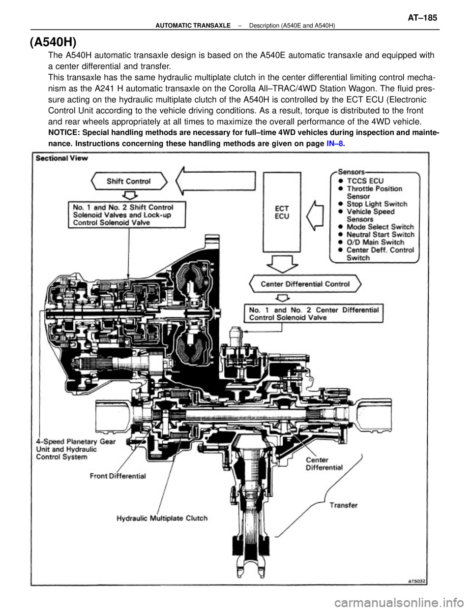
(A540H)
The A540H automatic transaxle design is based on the A540E automatic transaxle and equipped with
a center differential and transfer.
This transaxle has the same hydraulic multiplate clutch in the center differential limiting control mecha-
nism as the A241 H automatic transaxle on the Corolla All±TRAC/4WD Station Wagon. The fluid pres-
sure acting on the hydraulic multiplate clutch of the A540H is controlled by the ECT ECU (Electronic
Control Unit according to the vehicle driving conditions. As a result, torque is distributed to the front
and rear wheels appropriately at all times to maximize the overall performance of the 4WD vehicle.
NOTICE: Special handling methods are necessary for full±time 4WD vehicles during inspection and mainte-
nance. Instructions concerning these handling methods are given on page IN±8.
± AUTOMATIC TRANSAXLEDescription (A540E and A540H)AT±185