TOYOTA RAV4 1996 Service Repair Manual
Manufacturer: TOYOTA, Model Year: 1996, Model line: RAV4, Model: TOYOTA RAV4 1996Pages: 1632, PDF Size: 41.64 MB
Page 331 of 1632
and sliding surfaces with Dexron-II. Position snap ring on end of axle shaft, with opening facing
downward.
2. Install axle shaft by lightly tapping axle shaft into transaxle. Ensure axle shaft will move inward and
outward approximately .079-.120" (2.00-3.00 mm), and cannot be pulled from transaxle.
3. To install remaining components, reverse removal procedure. Tighten remaining bolts/nuts to
specification. See TORQUE SPECIFICATIONS
. Fill transaxle with Dexron-II (A/T models), or 75W-
90 gear oil with API GL-3, GL-4 or GL-5 rating (M/T models).
Disassembly (FWD M/T)
1. Remove boot clamps, and slide boots from joints. Paint reference marks on outer race and axle shaft for
reassembly reference. See Fig. 6
.
2. Using a screwdriver, remove snap ring from outer tulip race. Remove outer tulip race from inner joint and
axle shaft. Remove snap ring from end of axle shaft retaining inner joint. Paint reference marks on inner
joint, outer cage and axle shaft for reassembly reference.
3. Remove 6 balls and cage. Using a hammer and brass drift, tap inner joint from axle shaft. Remove inner
snap ring. Remove boots from axle shaft. Using a press, remove dust cover from right-side axle shaft.
Using a press and bearing splitter, remove dust cover from left-side inner joint tulip.
4. Disassemble right-side center axle shaft. Using snap ring pliers or a screwdriver, remove snap ring. Using
a press, remove bearing from axle. Using a screwdriver and hammer, remove outer dust deflector from
axle shaft.
Reassembly
1. Using a press, install NEW dust deflector on outboard end of axle shaft. Install NEW snap ring, then
press center bearing on axle shaft. Press NEW dust cover against bearing. On FWD M/T models,
clearance should be .039" (1.0 mm) between bearing and dust cover. On FWD A/T and AWD models,
clearance should be 3.39-3.43" (86-87 mm) between bearing and dust cover.
2. Using a press, install NEW dust cover on axle shaft. Right-side (transaxle side) dust cover must be
positioned 4.134-4.173" (105.0-106.0 mm) from end of axle shaft. Wrap splines on axle shaft with tape to
prevent damaging boots during installation.
3. Install NEW boots and NEW boot clamps on axle shaft. Install NEW snap ring on axle shaft. Install
inboard joint on axle shaft with small diameter side facing outboard joint. Ensure reference mark on inner
joint and axle shaft are aligned. Install NEW snap ring that retains inner joint on axle shaft.
4. Position outer cage and 6 balls on inner joint, and hold in place with grease. Apply grease supplied with
overhaul kit to inner joint and boot. Install inboard joint tulip (center shaft) on inner joint. Ensure match-
marks are aligned. Install NEW snap ring.
5. Apply grease supplied with overhaul kit into outer joint and boot. Install boot on inner housing and outer
joint. Ensure boots are seated in grooves on axle shaft. Adjust axle shaft to standard axle shaft length. See
AXLE SHAFT LENGTH SPECIFICATIONS
. See Fig. 7 . Install and tighten boot clamps to a
clearance of .047-.157" (1.2-4.0 mm).
Installation
NOTE: Manufacturer does not recommend overhaul of outer joint assembly.
1999 Toyota RAV4
1999-2000 DRIVE AXLES AWD & FWD Axle Shafts - RAV4 & RWD Axle Shafts - MR2
Microsoft
Sunday, November 22, 2009 10:08:21 AMPage 10 © 2005 Mitchell Repair Information Company, LLC.
Page 332 of 1632
1. To install, reverse removal procedure. Before installing axle shafts, install NEW snap ring on end of axle
shaft (except right side). Coat axle shaft seals in transaxle with grease. Coat axle shaft splines and sliding
surfaces with Dexron-II. Position snap ring on end of axle shaft, with opening facing downward.
2. Install axle shaft by lightly tapping axle shaft into transaxle. Ensure axle shaft will move inward and
outward approximately .079-.120" (2.00-3.00 mm), and cannot be pulled from transaxle.
3. To install remaining components, reverse removal procedure. Tighten fasteners to specification. See
TORQUE SPECIFICATIONS
. Fill transaxle with 75W-90 gear oil with API GL-3, GL-4 or GL-5
rating.
REAR AXLE SHAFTS
Removal (MR2)
1. Raise and support vehicle. Remove rear wheels. Remove engine undercovers. Drain differential oil into
proper container. Unstake drive shaft lock nut. Apply brakes and remove nut. Remove bolt and brake flex
hose bracket from shock absorber. Loosen 2 lower shock absorber bolts and nuts.
2. Remove mounting bolts/nuts and disconnect strut rod from axle carrier. Remove mounting bolts/nuts
from No. 1 lower suspension arm. Remove nut and No. 2 lower suspension arm. Remove 2 lower shock
absorber bolts and nuts. See Fig. 8
. Using plastic hammer, remove drive shaft from axle hub. DO NOT
damage oil seal, boots or dust seal. NOTE: DO NOT damage oil seal, axle shaft boots or Anti-Lock Brake System (ABS)
speed sensor rotor when removing axle shaft.
1999 Toyota RAV4
1999-2000 DRIVE AXLES AWD & FWD Axle Shafts - RAV4 & RWD Axle Shafts - MR2
Microsoft
Sunday, November 22, 2009 10:08:21 AMPage 11 © 2005 Mitchell Repair Information Company, LLC.
Page 333 of 1632
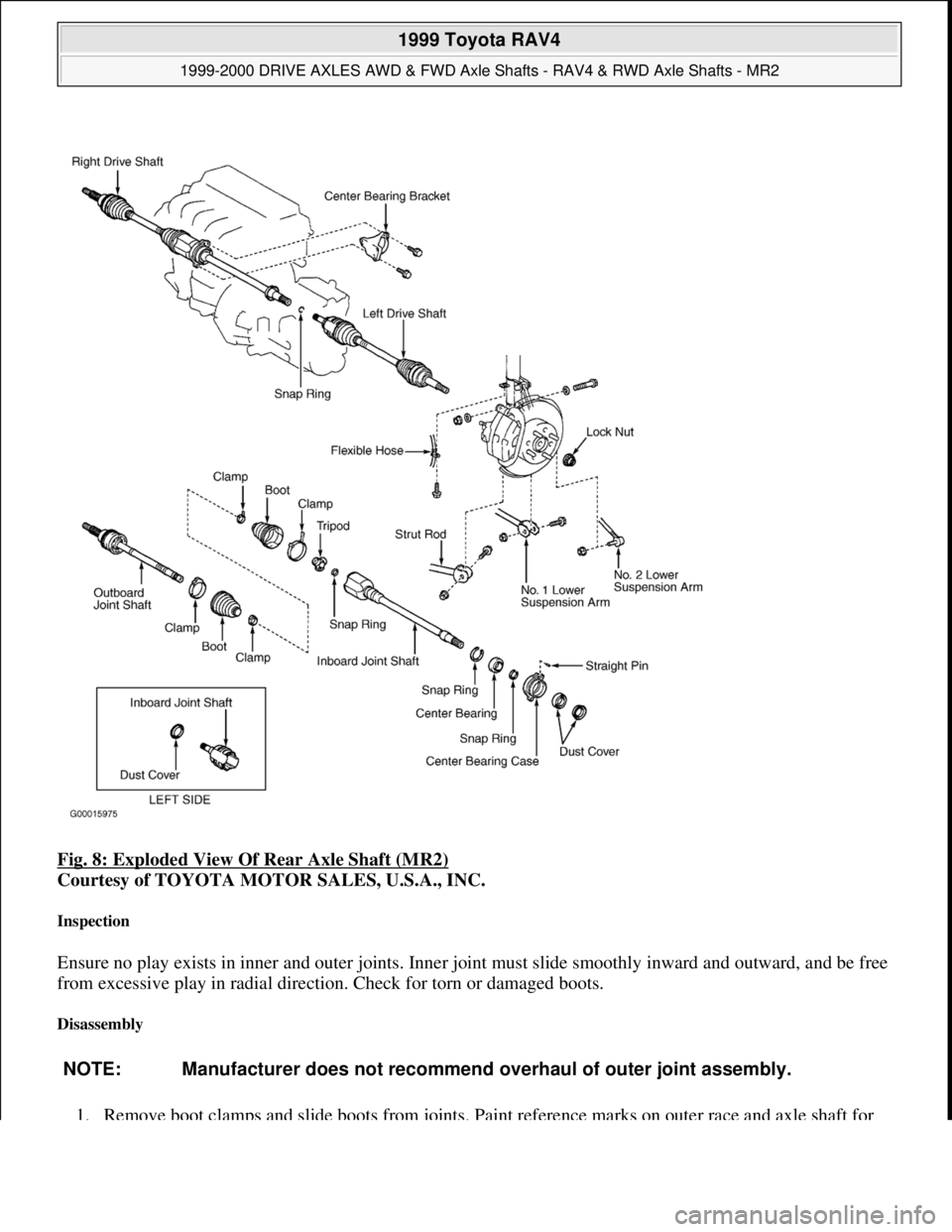
Fig. 8: Exploded View Of Rear Axle Shaft (MR2)
Courtesy of TOYOTA MOTOR SALES, U.S.A., INC.
Inspection
Ensure no play exists in inner and outer joints. Inner joint must slide smoothly inward and outward, and be free
from excessive play in radial direction. Check for torn or damaged boots.
Disassembly
1. Remove boot clamps and slide boots from joints. Paint reference marks on outer race and axle shaft for
NOTE: Manufacturer does not recommend overhaul of outer joint assembly.
1999 Toyota RAV4
1999-2000 DRIVE AXLES AWD & FWD Axle Shafts - RAV4 & RWD Axle Shafts - MR2
Microsoft
Sunday, November 22, 2009 10:08:21 AMPage 12 © 2005 Mitchell Repair Information Company, LLC.
Page 334 of 1632
reassembly reference.
2. Remove outer race from inboard tripod joint and axle shaft. Remove snap ring from end of axle shaft that
retains inboard tripod joint. Paint reference marks on tripod joint and axle shaft for reassembly reference.
3. Using a hammer and brass drift, tap inboard tripod joint from axle shaft. DO NOT tap on roller of tripod
joint during removal. Remove boots from axle shaft. Using a screwdriver and hammer, remove dust
deflector from axle shaft.
Reassembly
1. Using a press, install NEW dust deflector on left side axle shaft. Wrap splines on axle shaft with tape to
prevent damaging boots during installation. Using a punch and hammer, install straight pin onto center
bearing case on right side axle shaft. Press center bearing into bearing case. Install center bearing and
bearing case assembly to inboard joint shaft. Right side dust cover must be positioned so there
is .039" (1.0 mm) between dust cover and bearing assembly.
2. Install NEW boots and NEW boot clamps on axle shaft. Install NEW snap ring on axle shaft. Install
inboard tripod joint on axle shaft, with small diameter side facing outboard joint. Ensure reference mark
on inboard joint and axle shaft are aligned. Install NEW snap ring that retains inboard tripod joint on axle
shaft.
3. Apply grease supplied with overhaul kit to inner joint and boot. Install outer joint tulip on inner joint.
Ensure match-marks are aligned.
4. Apply grease supplied with overhaul kit into outer joint and boot. Install boot on inner housing and outer
joint. Ensure boots are seated in grooves on axle shaft. Adjust axle shaft to standard axle shaft length. See
AXLE SHAFT LENGTH SPECIFICATIONS
. See Fig. 9. Install and tighten boot clamps.
1999 Toyota RAV4
1999-2000 DRIVE AXLES AWD & FWD Axle Shafts - RAV4 & RWD Axle Shafts - MR2
Microsoft
Sunday, November 22, 2009 10:08:21 AMPage 13 © 2005 Mitchell Repair Information Company, LLC.
Page 335 of 1632
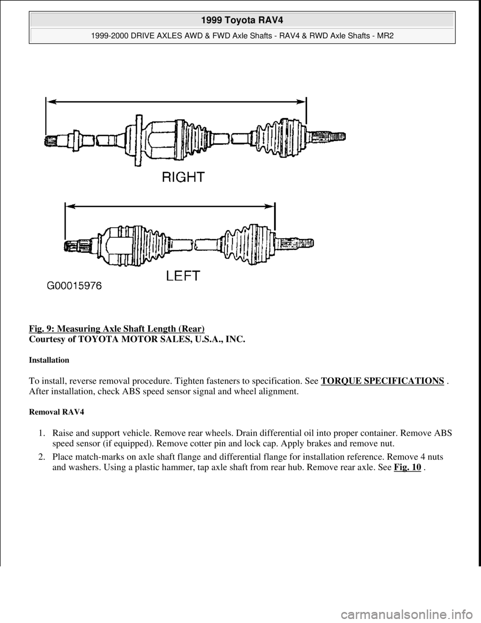
Fig. 9: Measuring Axle Shaft Length (Rear)
Courtesy of TOYOTA MOTOR SALES, U.S.A., INC.
Installation
To install, reverse removal procedure. Tighten fasteners to specification. See TORQUE SPECIFICATIONS .
After installation, check ABS speed sensor signal and wheel alignment.
Removal RAV4
1. Raise and support vehicle. Remove rear wheels. Drain differential oil into proper container. Remove ABS
speed sensor (if equipped). Remove cotter pin and lock cap. Apply brakes and remove nut.
2. Place match-marks on axle shaft flange and differential flange for installation reference. Remove 4 nuts
and washers. Using a plastic hammer, tap axle shaft from rear hub. Remove rear axle. See Fig. 10
.
1999 Toyota RAV4
1999-2000 DRIVE AXLES AWD & FWD Axle Shafts - RAV4 & RWD Axle Shafts - MR2
Microsoft
Sunday, November 22, 2009 10:08:21 AMPage 14 © 2005 Mitchell Repair Information Company, LLC.
Page 336 of 1632
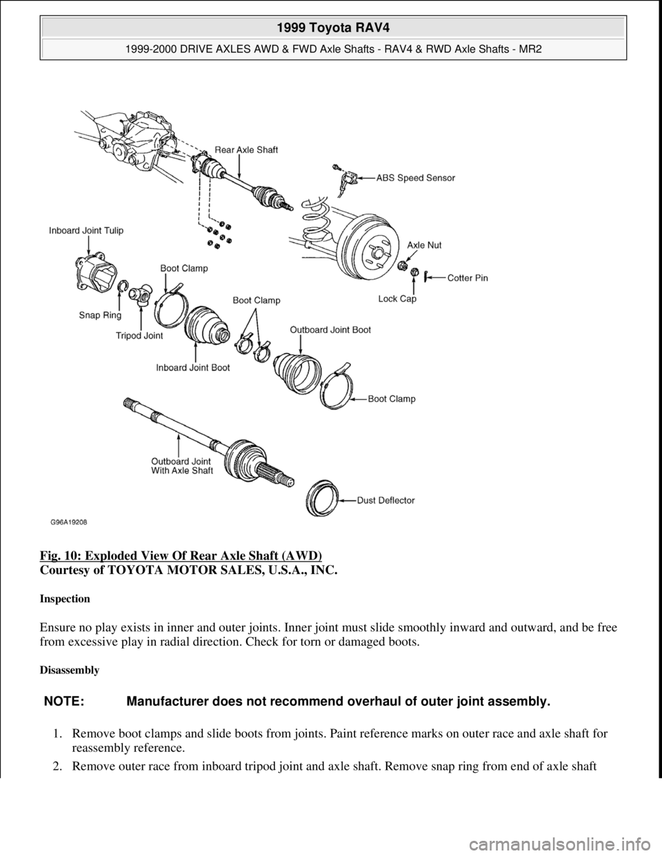
Fig. 10: Exploded View Of Rear Axle Shaft (AWD)
Courtesy of TOYOTA MOTOR SALES, U.S.A., INC.
Inspection
Ensure no play exists in inner and outer joints. Inner joint must slide smoothly inward and outward, and be free
from excessive play in radial direction. Check for torn or damaged boots.
Disassembly
1. Remove boot clamps and slide boots from joints. Paint reference marks on outer race and axle shaft for
reassembly reference.
2. Remove outer race from inboard tripod
joint and axle shaft. Remove snap ring from end of axle shaft
NOTE: Manufacturer does not recommend overhaul of outer joint assembly.
1999 Toyota RAV4
1999-2000 DRIVE AXLES AWD & FWD Axle Shafts - RAV4 & RWD Axle Shafts - MR2
Microsoft
Sunday, November 22, 2009 10:08:21 AMPage 15 © 2005 Mitchell Repair Information Company, LLC.
Page 337 of 1632
retaining inboard tripod joint. Paint reference marks on tripod joint and axle shaft for reassembly
reference.
3. Using a hammer and brass drift, tap inboard tripod joint from axle shaft. DO NOT tap on roller of tripod
joint during removal. Remove boots from axle shaft. Using a screwdriver and hammer, remove dust
deflector from axle shaft.
Reassembly
1. Using a press, install NEW dust deflector on axle shaft. Wrap splines on axle shaft with tape to prevent
damaging boots during installation.
2. Install NEW boots and NEW boot clamps on axle shaft. Install NEW snap ring on axle shaft. Install
inboard tripod joint on axle shaft, with small diameter side facing outboard joint. Ensure reference mark
on inboard joint and axle shaft are aligned. Install NEW snap ring that retains inboard tripod joint on axle
shaft.
3. Apply grease supplied with overhaul kit to inner joint and boot. Install outer joint tulip on inner joint.
Ensure match-marks are aligned.
4. Apply grease supplied with overhaul kit into outer joint and boot. Install boot on inner housing and outer
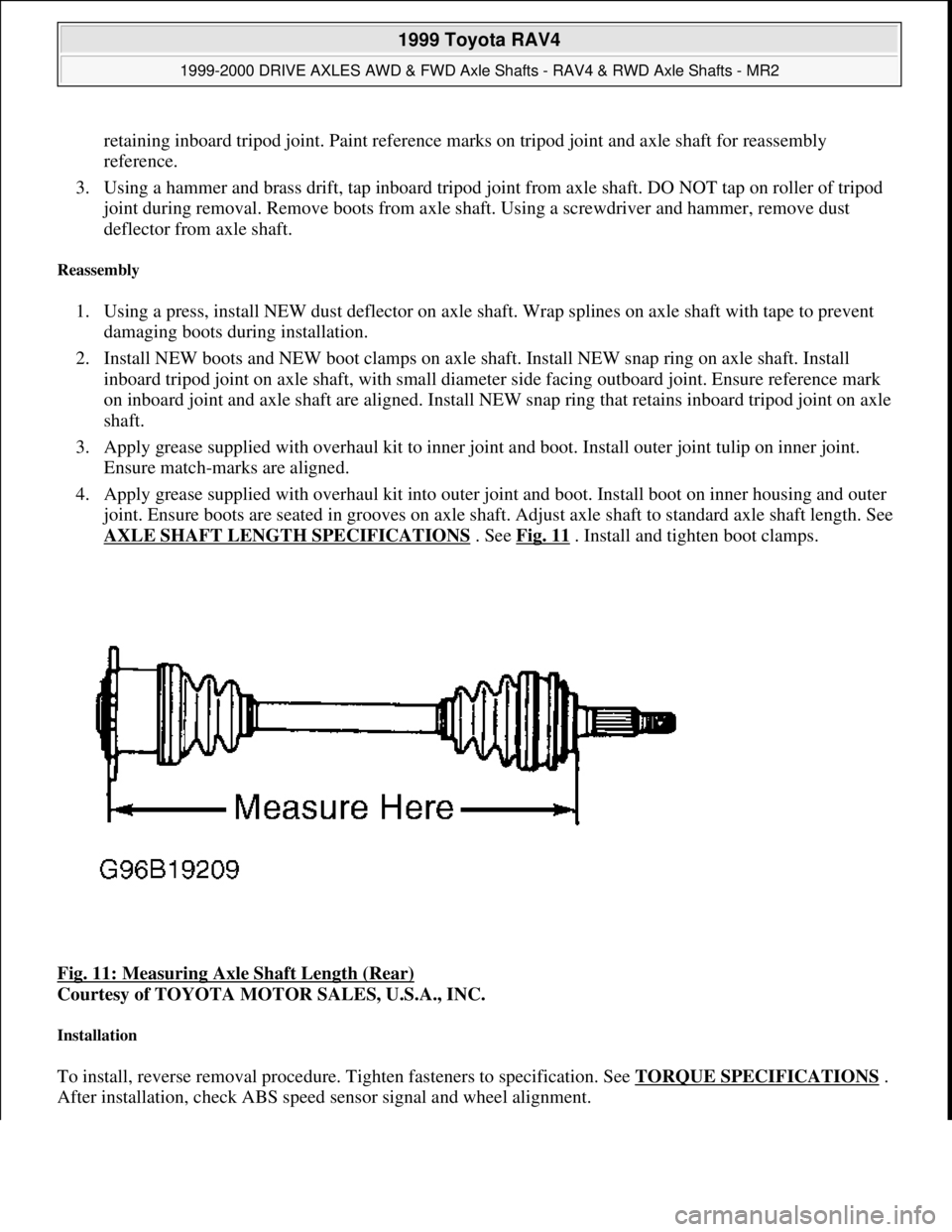
joint. Ensure boots are seated in grooves on axle shaft. Adjust axle shaft to standard axle shaft length. See
AXLE SHAFT LENGTH SPECIFICATIONS
. See Fig. 11 . Install and tighten boot clamps.
Fig. 11: Measuring Axle Shaft Length (Rear)
Courtesy of TOYOTA MOTOR SALES, U.S.A., INC.
Installation
To install, reverse removal procedure. Tighten fasteners to specification. See TORQUE SPECIFICATIONS .
After installation, check ABS speed sensor si
gnal and wheel alignment.
1999 Toyota RAV4
1999-2000 DRIVE AXLES AWD & FWD Axle Shafts - RAV4 & RWD Axle Shafts - MR2
Microsoft
Sunday, November 22, 2009 10:08:21 AMPage 16 © 2005 Mitchell Repair Information Company, LLC.
Page 338 of 1632
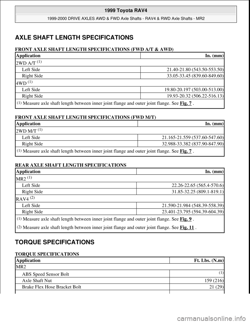
AXLE SHAFT LENGTH SPECIFICATIONS
FRONT AXLE SHAFT LENGTH SPECIFICATIONS (FWD A/T & AWD)
FRONT AXLE SHAFT LENGTH SPECIFICATIONS (FWD M/T)
REAR AXLE SHAFT LENGTH SPECIFICATIONS
TORQUE SPECIFICATIONS
TORQUE SPECIFICATIONS
ApplicationIn. (mm)
2WD A/T (1)
Left Side21.40-21.80 (543.50-553.50)
Right Side33.05-33.45 (839.60-849.60)
4WD (1)
Left Side19.80-20.197 (503.00-513.00)
Right Side19.93-20.32 (506.22-516.13)
(1)Measure axle shaft length between inner joint flange and outer joint flange. See Fig. 7 .
ApplicationIn. (mm)
2WD M/T (1)
Left Side21.165-21.559 (537.60-547.60)
Right Side32.988-33.382 (837.90-847.90)
(1)Measure axle shaft length between inner joint flange and outer joint flange. See Fig. 7 .
ApplicationIn. (mm)
MR2 (1)
Left Side22.26-22.65 (565.4-570.6)
Right Side31.85-32.25 (809.1-819.1)
RAV4 (2)
Left Side21.590-21.984 (548.39-558.39)
Right Side23.401-23.795 (594.39-604.39)
(1)Measure axle shaft length between inner joint flange and outer joint flange. See Fig. 9 .
(2)Measure axle shaft length between inner joint flange and outer joint flange. See Fig. 11 .
ApplicationFt. Lbs. (N.m)
MR2
ABS Speed Sensor Bolt(1)
Axle Shaft Nut159 (216)
Brake Flex Hose Bracket Bolt21 (29)
1999 Toyota RAV4
1999-2000 DRIVE AXLES AWD & FWD Axle Shafts - RAV4 & RWD Axle Shafts - MR2
Microsoft
Sunday, November 22, 2009 10:08:21 AMPage 17 © 2005 Mitchell Repair Information Company, LLC.
Page 339 of 1632
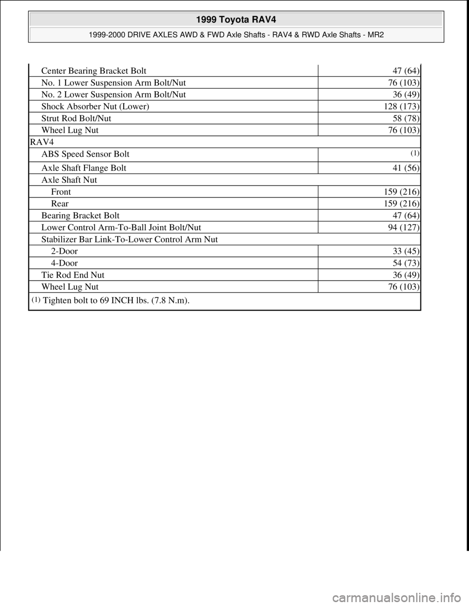
Center Bearing Bracket Bolt47 (64)
No. 1 Lower Suspension Arm Bolt/Nut76 (103)
No. 2 Lower Suspension Arm Bolt/Nut36 (49)
Shock Absorber Nut (Lower)128 (173)
Strut Rod Bolt/Nut58 (78)
Wheel Lug Nut76 (103)
RAV4
ABS Speed Sensor Bolt(1)
Axle Shaft Flange Bolt41 (56)
Axle Shaft Nut
Front159 (216)
Rear159 (216)
Bearing Bracket Bolt47 (64)
Lower Control Arm-To-Ball Joint Bolt/Nut94 (127)
Stabilizer Bar Link-To-Lower Control Arm Nut
2-Door33 (45)
4-Door54 (73)
Tie Rod End Nut36 (49)
Wheel Lug Nut76 (103)
(1)Tighten bolt to 69 INCH lbs. (7.8 N.m).
1999 Toyota RAV4
1999-2000 DRIVE AXLES AWD & FWD Axle Shafts - RAV4 & RWD Axle Shafts - MR2
Microsoft
Sunday, November 22, 2009 10:08:21 AMPage 18 © 2005 Mitchell Repair Information Company, LLC.
Page 340 of 1632
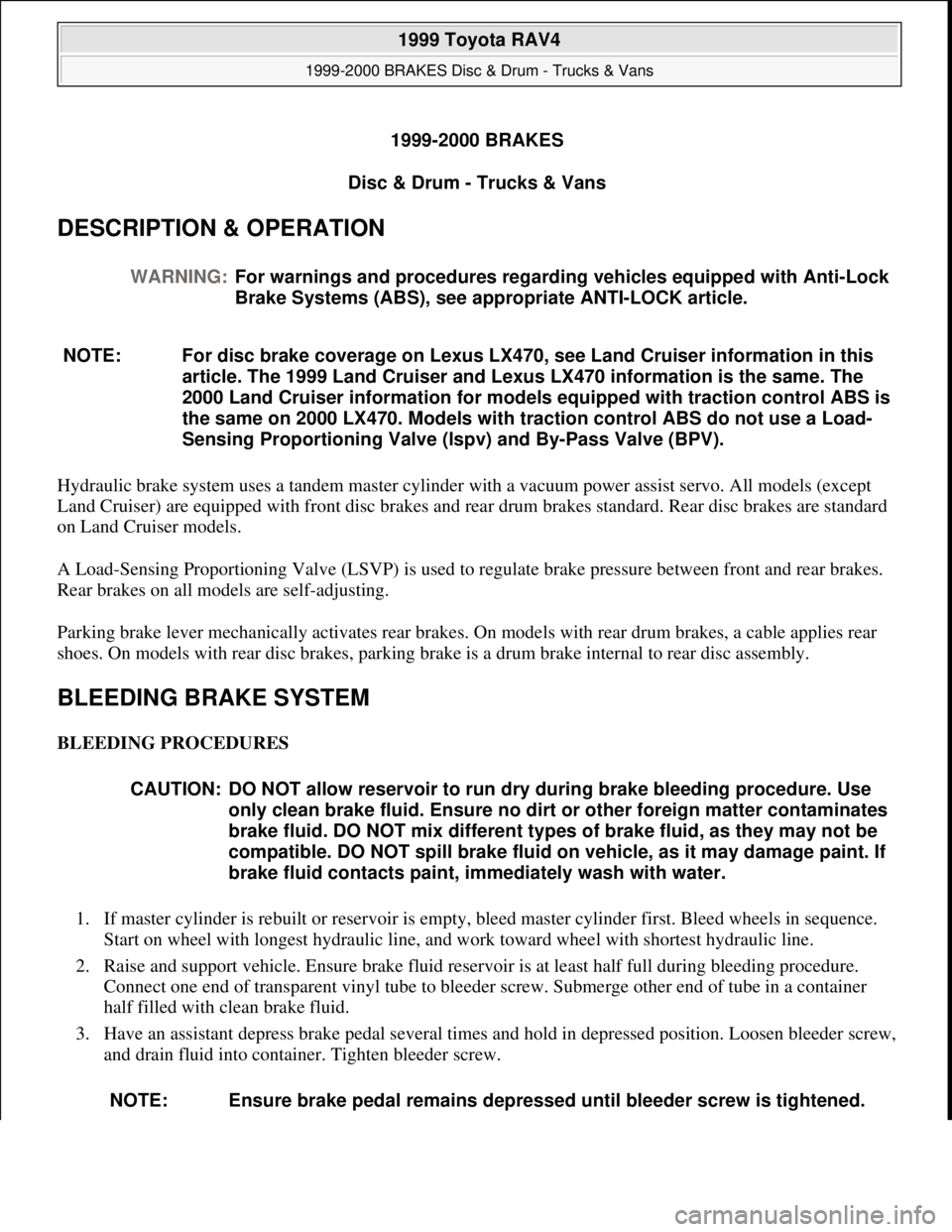
1999-2000 BRAKES
Disc & Drum - Trucks & Vans
DESCRIPTION & OPERATION
Hydraulic brake system uses a tandem master cylinder with a vacuum power assist servo. All models (except
Land Cruiser) are equipped with front disc brakes and rear drum brakes standard. Rear disc brakes are standard
on Land Cruiser models.
A Load-Sensing Proportioning Valve (LSVP) is used to regulate brake pressure between front and rear brakes.
Rear brakes on all models are self-adjusting.
Parking brake lever mechanically activates rear brakes. On models with rear drum brakes, a cable applies rear
shoes. On models with rear disc brakes, parking brake is a drum brake internal to rear disc assembly.
BLEEDING BRAKE SYSTEM
BLEEDING PROCEDURES
1. If master cylinder is rebuilt or reservoir is empty, bleed master cylinder first. Bleed wheels in sequence.
Start on wheel with longest hydraulic line, and work toward wheel with shortest hydraulic line.
2. Raise and support vehicle. Ensure brake fluid reservoir is at least half full during bleeding procedure.
Connect one end of transparent vinyl tube to bleeder screw. Submerge other end of tube in a container
half filled with clean brake fluid.
3. Have an assistant depress brake pedal several times and hold in depressed position. Loosen bleeder screw,
and drain fluid into container. Tighten bleeder screw. WARNING:For warnings and procedures regarding vehicles equipped with Anti-Lock
Brake Systems (ABS), see appropriate ANTI-LOCK article.
NOTE: For disc brake coverage on Lexus LX470, see Land Cruiser information in this
article. The 1999 Land Cruiser and Lexus LX470 information is the same. The
2000 Land Cruiser information for models equipped with traction control ABS is
the same on 2000 LX470. Models with traction control ABS do not use a Load-
Sensing Proportioning Valve (lspv) and By-Pass Valve (BPV).
CAUTION: DO NOT allow reservoir to run dry during brake bleeding procedure. Use
only clean brake fluid. Ensure no dirt or other foreign matter contaminates
brake fluid. DO NOT mix different types of brake fluid, as they may not be
compatible. DO NOT spill brake fluid on vehicle, as it may damage paint. If
brake fluid contacts paint, immediately wash with water.
NOTE: Ensure brake pedal remains depressed until bleeder screw is tightened.
1999 Toyota RAV4
1999-2000 BRAKES Disc & Drum - Trucks & Vans
1999 Toyota RAV4
1999-2000 BRAKES Disc & Drum - Trucks & Vans
Microsoft
Sunday, November 22, 2009 10:07:28 AMPage 1 © 2005 Mitchell Repair Information Company, LLC.
Microsoft
Sunday, November 22, 2009 10:07:32 AMPage 1 © 2005 Mitchell Repair Information Company, LLC.