TOYOTA RAV4 2006 Service Repair Manual
Manufacturer: TOYOTA, Model Year: 2006,
Model line: RAV4,
Model: TOYOTA RAV4 2006
Pages: 2000, PDF Size: 45.84 MB
TOYOTA RAV4 2006 Service Repair Manual
RAV4 2006
TOYOTA
TOYOTA
https://www.carmanualsonline.info/img/14/57463/w960_57463-0.png
TOYOTA RAV4 2006 Service Repair Manual
Trending: Bearing, overdrive, ECO mode, suspension, power steering fluid, fuel pressure, check engine light
Page 1021 of 2000
U140F AUTOMATIC TRANSAXLE – DIFFERENTIAL CASEAX–261
AX
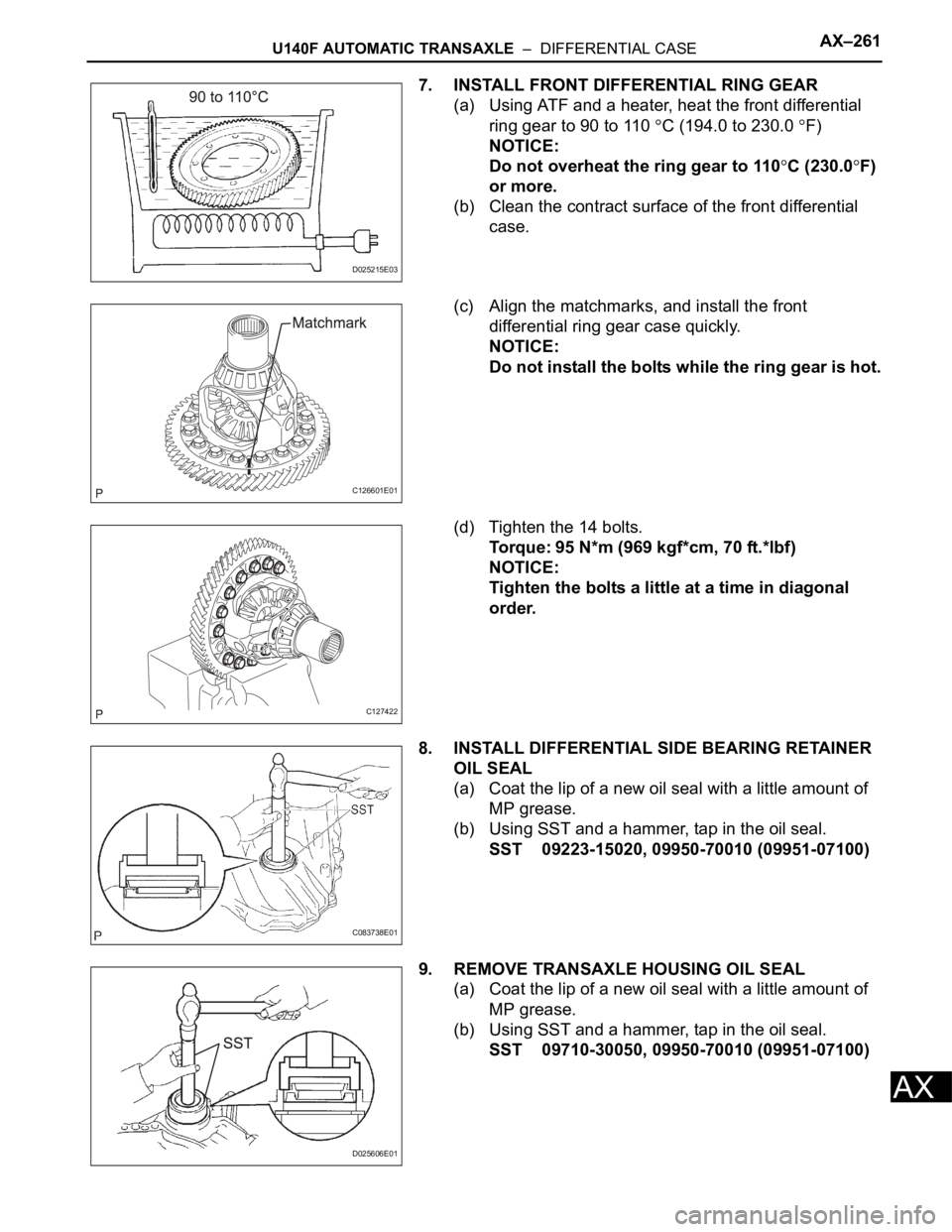
7. INSTALL FRONT DIFFERENTIAL RING GEAR
(a) Using ATF and a heater, heat the front differential
ring gear to 90 to 110
C (194.0 to 230.0 F)
NOTICE:
Do not overheat the ring gear to 110
C (230.0F)
or more.
(b) Clean the contract surface of the front differential
case.
(c) Align the matchmarks, and install the front
differential ring gear case quickly.
NOTICE:
Do not install the bolts while the ring gear is hot.
(d) Tighten the 14 bolts.
Torque: 95 N*m (969 kgf*cm, 70 ft.*lbf)
NOTICE:
Tighten the bolts a little at a time in diagonal
order.
8. INSTALL DIFFERENTIAL SIDE BEARING RETAINER
OIL SEAL
(a) Coat the lip of a new oil seal with a little amount of
MP grease.
(b) Using SST and a hammer, tap in the oil seal.
SST 09223-15020, 09950-70010 (09951-07100)
9. REMOVE TRANSAXLE HOUSING OIL SEAL
(a) Coat the lip of a new oil seal with a little amount of
MP grease.
(b) Using SST and a hammer, tap in the oil seal.
SST 09710-30050, 09950-70010 (09951-07100)
D025215E03
C126601E01
C127422
C083738E01
D025606E01
Page 1022 of 2000
AX–6U151E AUTOMATIC TRANSAXLE – AUTOMATIC TRANSAXLE SYSTEM
AX
SYSTEM DIAGRAM
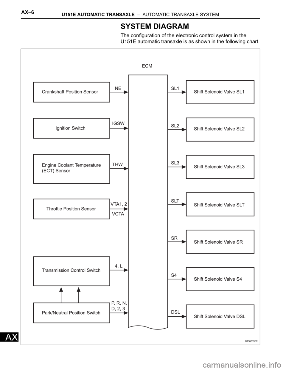
The configuration of the electronic control system in the
U151E automatic transaxle is as shown in the following chart.
C136233E01
Page 1023 of 2000
U151E AUTOMATIC TRANSAXLE – AUTOMATIC TRANSAXLE SYSTEMAX–7
AX
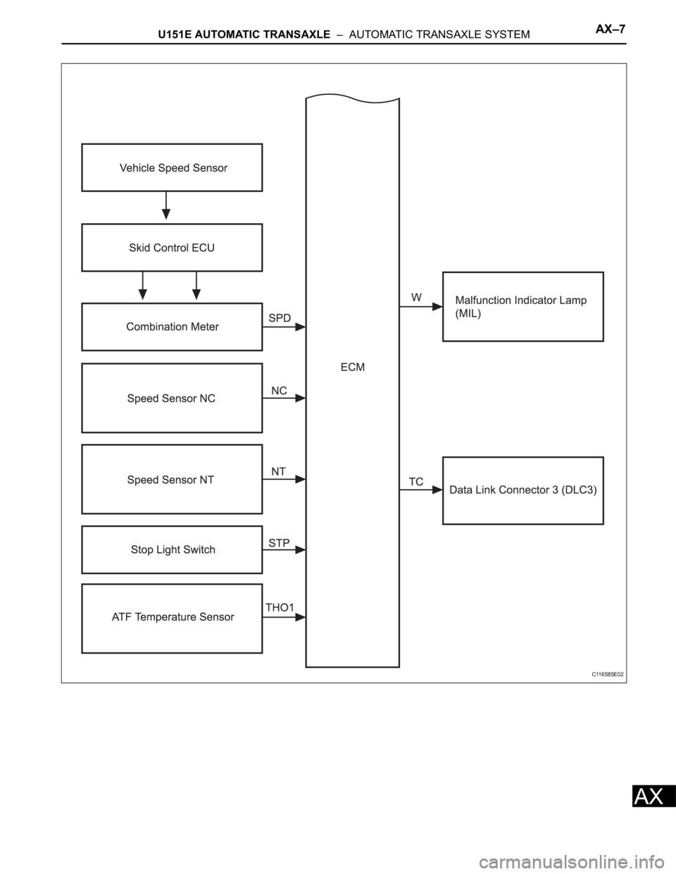
C116585E02
Page 1024 of 2000
AX–8U151E AUTOMATIC TRANSAXLE – AUTOMATIC TRANSAXLE SYSTEM
AX
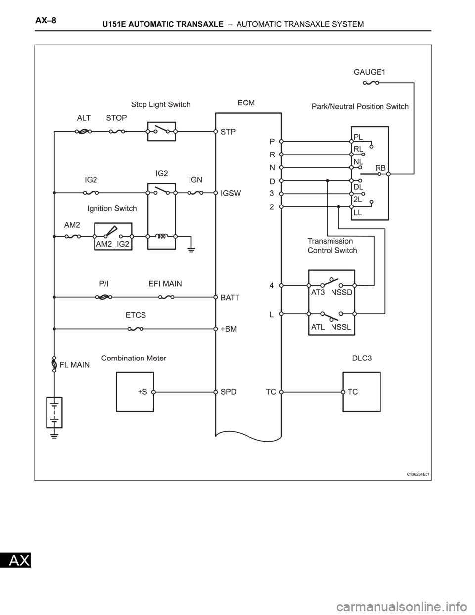
C136234E01
Page 1025 of 2000
U151E AUTOMATIC TRANSAXLE – AUTOMATIC TRANSAXLE SYSTEMAX–9
AX
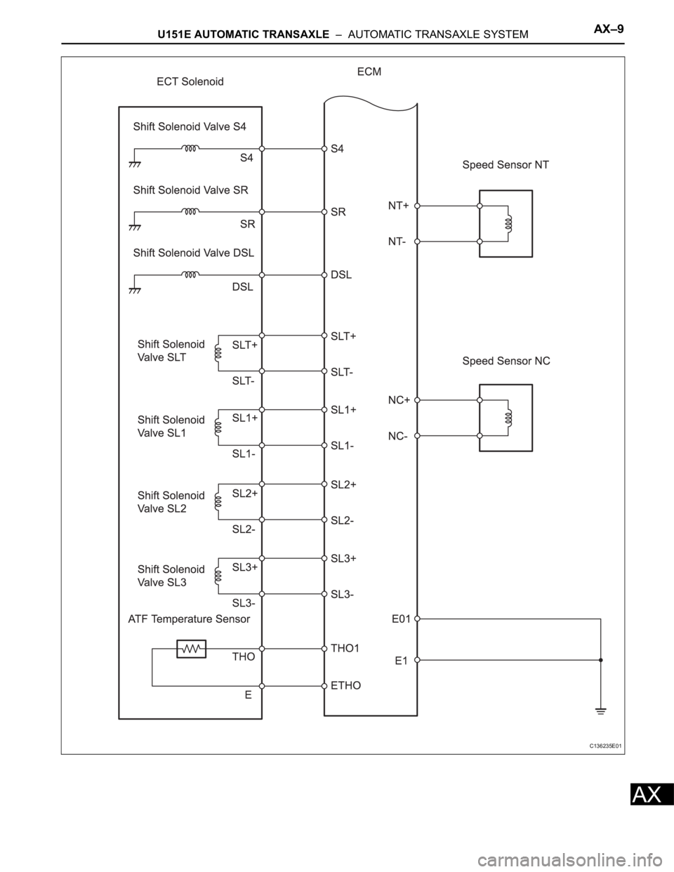
C136235E01
Page 1026 of 2000
AX–10U151E AUTOMATIC TRANSAXLE – AUTOMATIC TRANSAXLE SYSTEM
AX
SYSTEM DESCRIPTION
1. SYSTEM DESCRIPTION
(a) The Electronic Controlled Automatic Transaxle
(ECT) is an automatic transaxle that electronically
controls shift timing using the Engine Control
Module (ECM). The ECM detects electrical signals
that indicate engine and driving conditions, and
controls the shift point based on driver habits and
road conditions. As a result, fuel efficiency and
power transaxle performance are improved.
Shift shock is reduced by controlling the engine and
transaxle simultaneously.
In addition, the ECT has the following features:
• Diagnostic function.
• Fail-safe function when a malfunction occurs.
Page 1027 of 2000
U151E AUTOMATIC TRANSAXLE – AUTOMATIC TRANSAXLE SYSTEMAX–11
AX
HOW TO PROCEED WITH
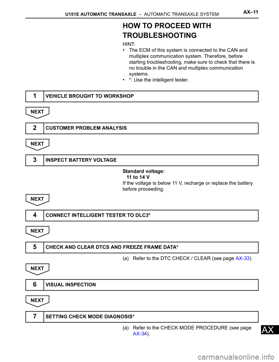
TROUBLESHOOTING
HINT:
• The ECM of this system is connected to the CAN and
multiplex communication system. Therefore, before
starting troubleshooting, make sure to check that there is
no trouble in the CAN and multiplex communication
systems.
• *: Use the intelligent tester.
NEXT
NEXT
Standard voltage:
11 to 14 V
If the voltage is below 11 V, recharge or replace the battery
before proceeding.
NEXT
NEXT
(a) Refer to the DTC CHECK / CLEAR (see page AX-33).
NEXT
NEXT
(a) Refer to the CHECK MODE PROCEDURE (see page
AX-34).
1VEHICLE BROUGHT TO WORKSHOP
2CUSTOMER PROBLEM ANALYSIS
3INSPECT BATTERY VOLTAGE
4CONNECT INTELLIGENT TESTER TO DLC3*
5CHECK AND CLEAR DTCS AND FREEZE FRAME DATA*
6VISUAL INSPECTION
7SETTING CHECK MODE DIAGNOSIS*
Page 1028 of 2000
AX–12U151E AUTOMATIC TRANSAXLE – AUTOMATIC TRANSAXLE SYSTEM
AX
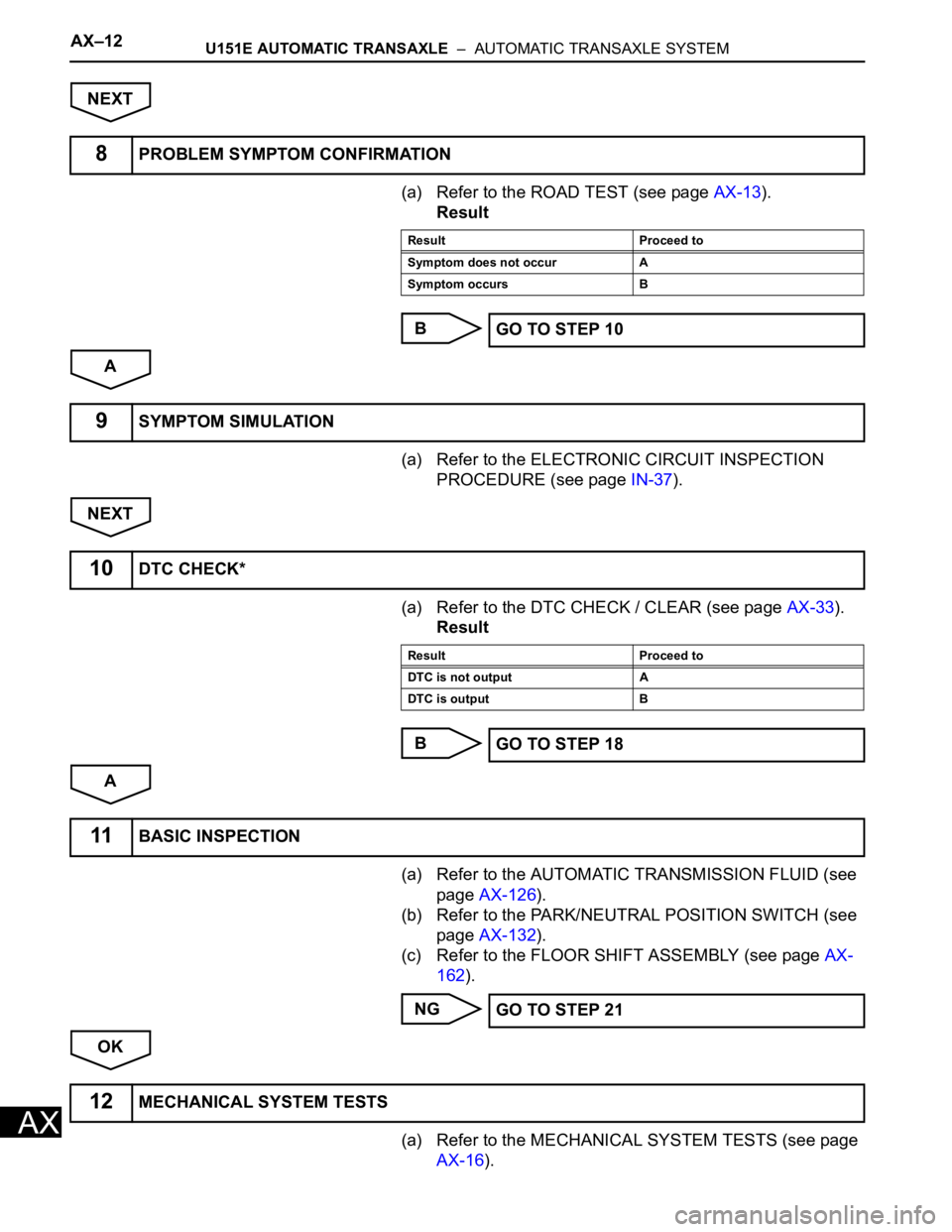
NEXT
(a) Refer to the ROAD TEST (see page AX-13).
Result
B
A
(a) Refer to the ELECTRONIC CIRCUIT INSPECTION
PROCEDURE (see page IN-37).
NEXT
(a) Refer to the DTC CHECK / CLEAR (see page AX-33).
Result
B
A
(a) Refer to the AUTOMATIC TRANSMISSION FLUID (see
page AX-126).
(b) Refer to the PARK/NEUTRAL POSITION SWITCH (see
page AX-132).
(c) Refer to the FLOOR SHIFT ASSEMBLY (see page AX-
162).
NG
OK
(a) Refer to the MECHANICAL SYSTEM TESTS (see page
AX-16).
8PROBLEM SYMPTOM CONFIRMATION
Result Proceed to
Symptom does not occur A
Symptom occurs B
GO TO STEP 10
9SYMPTOM SIMULATION
10DTC CHECK*
Result Proceed to
DTC is not output A
DTC is output B
GO TO STEP 18
11BASIC INSPECTION
GO TO STEP 21
12MECHANICAL SYSTEM TESTS
Page 1029 of 2000
U151E AUTOMATIC TRANSAXLE – AUTOMATIC TRANSAXLE SYSTEMAX–13
AX
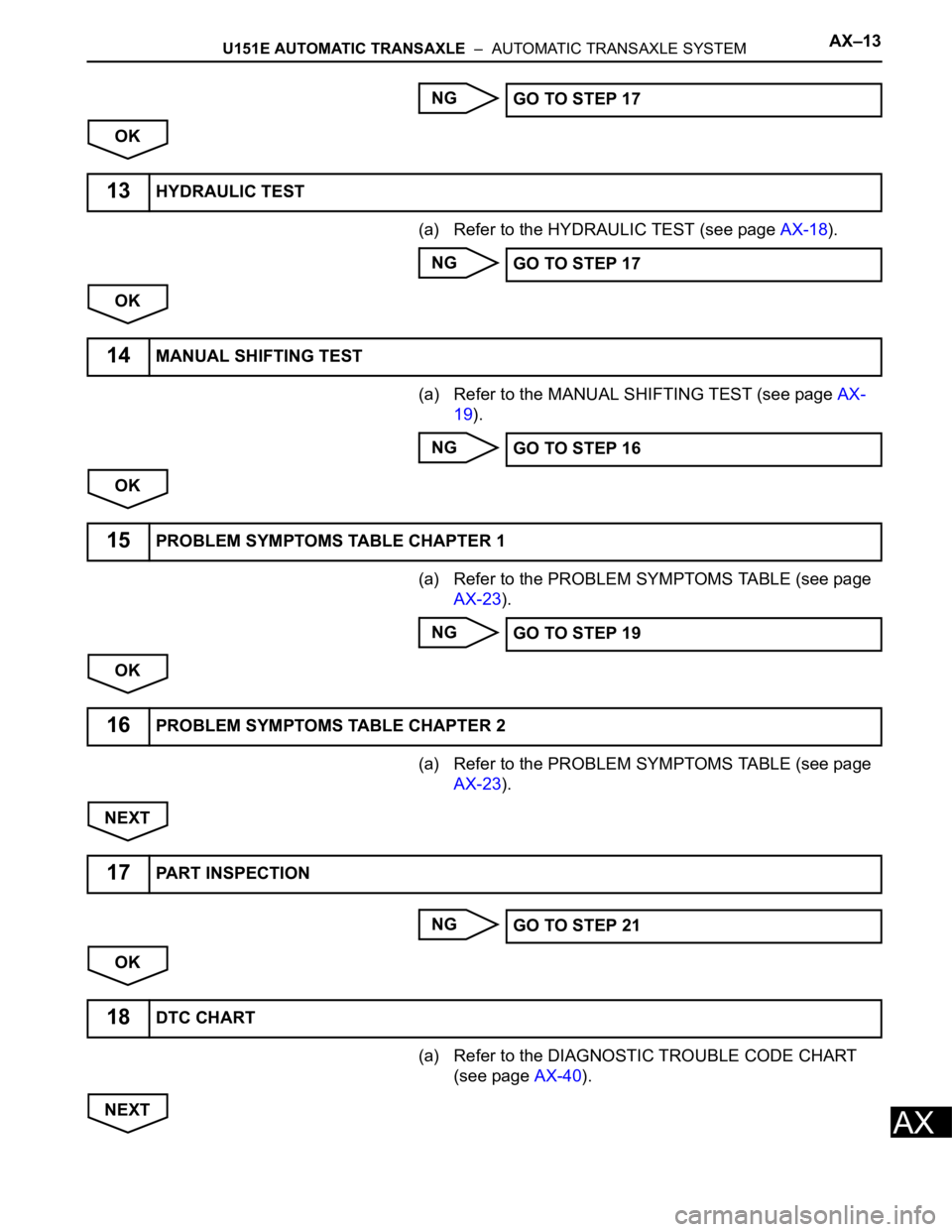
NG
OK
(a) Refer to the HYDRAULIC TEST (see page AX-18).
NG
OK
(a) Refer to the MANUAL SHIFTING TEST (see page AX-
19).
NG
OK
(a) Refer to the PROBLEM SYMPTOMS TABLE (see page
AX-23).
NG
OK
(a) Refer to the PROBLEM SYMPTOMS TABLE (see page
AX-23).
NEXT
NG
OK
(a) Refer to the DIAGNOSTIC TROUBLE CODE CHART
(see page AX-40).
NEXTGO TO STEP 17
13HYDRAULIC TEST
GO TO STEP 17
14MANUAL SHIFTING TEST
GO TO STEP 16
15PROBLEM SYMPTOMS TABLE CHAPTER 1
GO TO STEP 19
16PROBLEM SYMPTOMS TABLE CHAPTER 2
17PART INSPECTION
GO TO STEP 21
18DTC CHART
Page 1030 of 2000
AX–14U151E AUTOMATIC TRANSAXLE – AUTOMATIC TRANSAXLE SYSTEM
AX
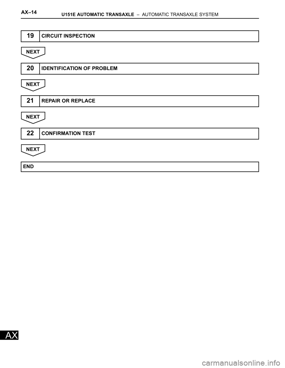
NEXT
NEXT
NEXT
NEXT
19CIRCUIT INSPECTION
20IDENTIFICATION OF PROBLEM
21REPAIR OR REPLACE
22CONFIRMATION TEST
END
Trending: Install air manifold, Front bar, Engine cover, steering column, jacking, radiator cap, electrical diagram

