TOYOTA RAV4 2006 Service Repair Manual
Manufacturer: TOYOTA, Model Year: 2006, Model line: RAV4, Model: TOYOTA RAV4 2006Pages: 2000, PDF Size: 45.84 MB
Page 1011 of 2000
U140F AUTOMATIC TRANSAXLE – OIL PUMPAX–221
AX
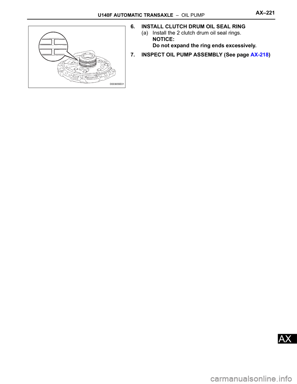
6. INSTALL CLUTCH DRUM OIL SEAL RING
(a) Install the 2 clutch drum oil seal rings.
NOTICE:
Do not expand the ring ends excessively.
7. INSPECT OIL PUMP ASSEMBLY (See page AX-218)
D003655E01
Page 1012 of 2000
AX–224U140F AUTOMATIC TRANSAXLE – SECOND BRAKE PISTON
AX
REASSEMBLY
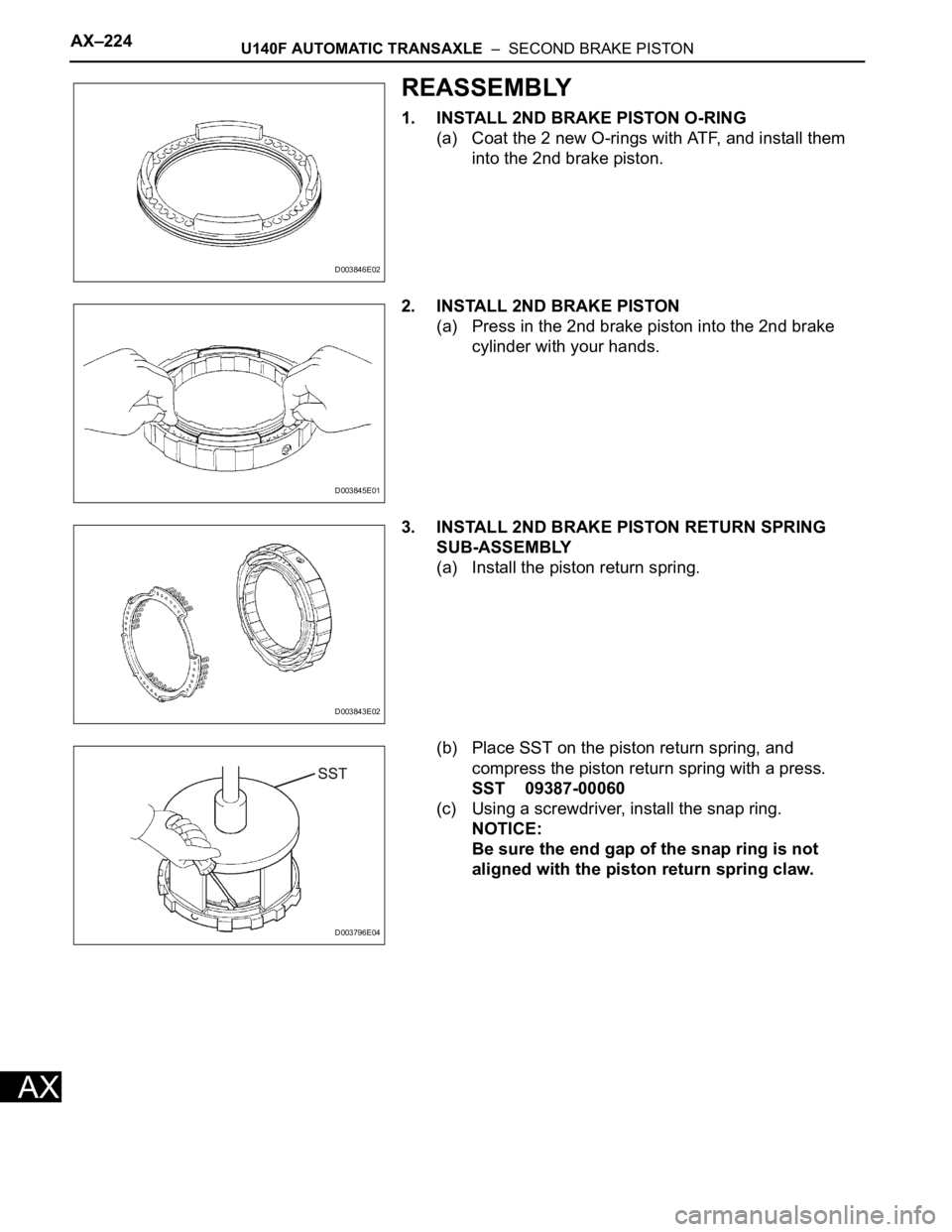
1. INSTALL 2ND BRAKE PISTON O-RING
(a) Coat the 2 new O-rings with ATF, and install them
into the 2nd brake piston.
2. INSTALL 2ND BRAKE PISTON
(a) Press in the 2nd brake piston into the 2nd brake
cylinder with your hands.
3. INSTALL 2ND BRAKE PISTON RETURN SPRING
SUB-ASSEMBLY
(a) Install the piston return spring.
(b) Place SST on the piston return spring, and
compress the piston return spring with a press.
SST 09387-00060
(c) Using a screwdriver, install the snap ring.
NOTICE:
Be sure the end gap of the snap ring is not
aligned with the piston return spring claw.
D003846E02
D003845E01
D003843E02
D003796E04
Page 1013 of 2000
AX–234U140F AUTOMATIC TRANSAXLE – DIRECT CLUTCH
AX
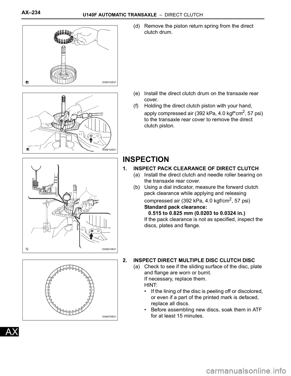
(d) Remove the piston return spring from the direct
clutch drum.
(e) Install the direct clutch drum on the transaxle rear
cover.
(f) Holding the direct clutch piston with your hand,
apply compressed air (392 kPa, 4.0 kgf*cm
2, 57 psi)
to the transaxle rear cover to remove the direct
clutch piston.
INSPECTION
1. INSPECT PACK CLEARANCE OF DIRECT CLUTCH
(a) Install the direct clutch and needle roller bearing on
the transaxle rear cover.
(b) Using a dial indicator, measure the forward clutch
pack clearance while applying and releasing
compressed air (392 kPa, 4.0 kgf/cm
2, 57 psi)
Standard pack clearance:
0.515 to 0.825 mm (0.0203 to 0.0324 in.)
If the pack clearance is not as specified, inspect the
discs, plates and flange.
2. INSPECT DIRECT MULTIPLE DISC CLUTCH DISC
(a) Check to see if the sliding surface of the disc, plate
and flange are worn or burnt.
If necessary, replace them.
HINT:
• If the lining of the disc is peeling off or discolored,
or even if a part of the printed mark is defaced,
replace all discs.
• Before assembling new discs, soak them in ATF
for at least 15 minutes.
D008102E01
D008103E01
D009210E01
D004079E01
Page 1014 of 2000
U140F AUTOMATIC TRANSAXLE – DIRECT CLUTCHAX–235
AX
3. INSPECT DIRECT CLUTCH RETURN SPRING SUB-
ASSEMBLY
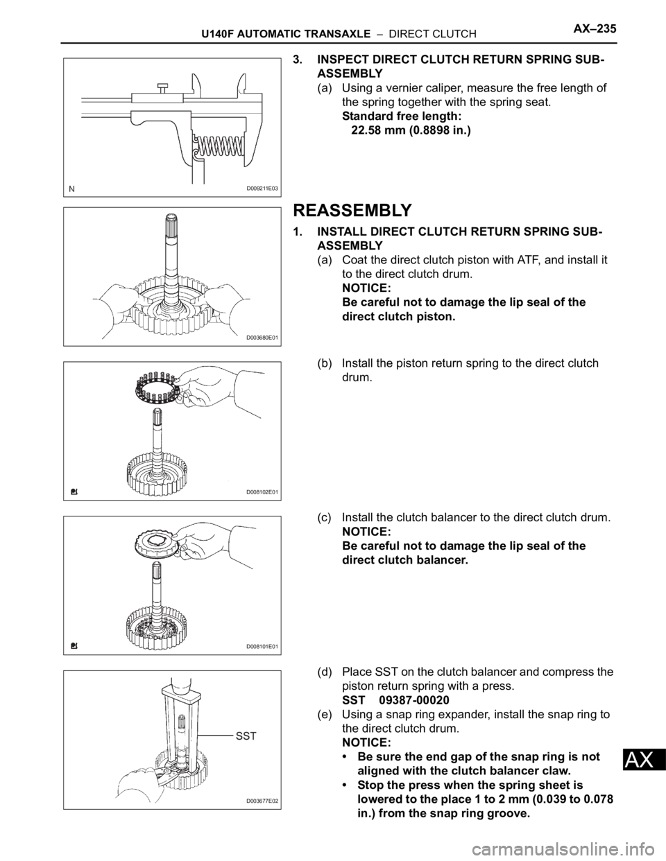
(a) Using a vernier caliper, measure the free length of
the spring together with the spring seat.
Standard free length:
22.58 mm (0.8898 in.)
REASSEMBLY
1. INSTALL DIRECT CLUTCH RETURN SPRING SUB-
ASSEMBLY
(a) Coat the direct clutch piston with ATF, and install it
to the direct clutch drum.
NOTICE:
Be careful not to damage the lip seal of the
direct clutch piston.
(b) Install the piston return spring to the direct clutch
drum.
(c) Install the clutch balancer to the direct clutch drum.
NOTICE:
Be careful not to damage the lip seal of the
direct clutch balancer.
(d) Place SST on the clutch balancer and compress the
piston return spring with a press.
SST 09387-00020
(e) Using a snap ring expander, install the snap ring to
the direct clutch drum.
NOTICE:
• Be sure the end gap of the snap ring is not
aligned with the clutch balancer claw.
• Stop the press when the spring sheet is
lowered to the place 1 to 2 mm (0.039 to 0.078
in.) from the snap ring groove.
D009211E03
D003680E01
D008102E01
D008101E01
D003677E02
Page 1015 of 2000
AX–236U140F AUTOMATIC TRANSAXLE – DIRECT CLUTCH
AX
• This prevents the spring sheet from being
deformed.
• Do not expand the snap ring excessively.
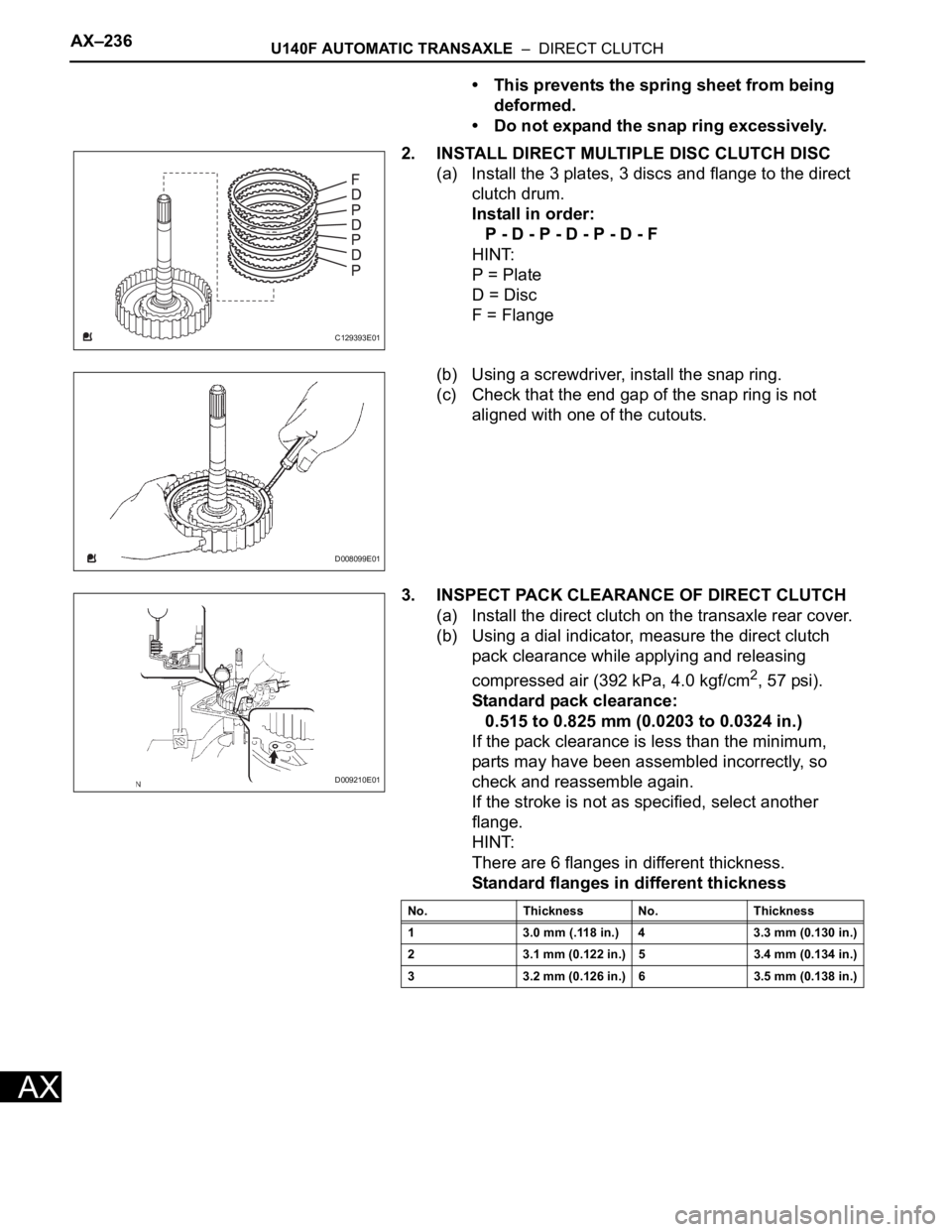
2. INSTALL DIRECT MULTIPLE DISC CLUTCH DISC
(a) Install the 3 plates, 3 discs and flange to the direct
clutch drum.
Install in order:
P - D - P - D - P - D - F
HINT:
P = Plate
D = Disc
F = Flange
(b) Using a screwdriver, install the snap ring.
(c) Check that the end gap of the snap ring is not
aligned with one of the cutouts.
3. INSPECT PACK CLEARANCE OF DIRECT CLUTCH
(a) Install the direct clutch on the transaxle rear cover.
(b) Using a dial indicator, measure the direct clutch
pack clearance while applying and releasing
compressed air (392 kPa, 4.0 kgf/cm
2, 57 psi).
Standard pack clearance:
0.515 to 0.825 mm (0.0203 to 0.0324 in.)
If the pack clearance is less than the minimum,
parts may have been assembled incorrectly, so
check and reassemble again.
If the stroke is not as specified, select another
flange.
HINT:
There are 6 flanges in different thickness.
Standard flanges in different thickness
C129393E01
D008099E01
D009210E01
No. Thickness No. Thickness
1 3.0 mm (.118 in.) 4 3.3 mm (0.130 in.)
2 3.1 mm (0.122 in.) 5 3.4 mm (0.134 in.)
3 3.2 mm (0.126 in.) 6 3.5 mm (0.138 in.)
Page 1016 of 2000
U140F AUTOMATIC TRANSAXLE – DIRECT CLUTCHAX–237
AX
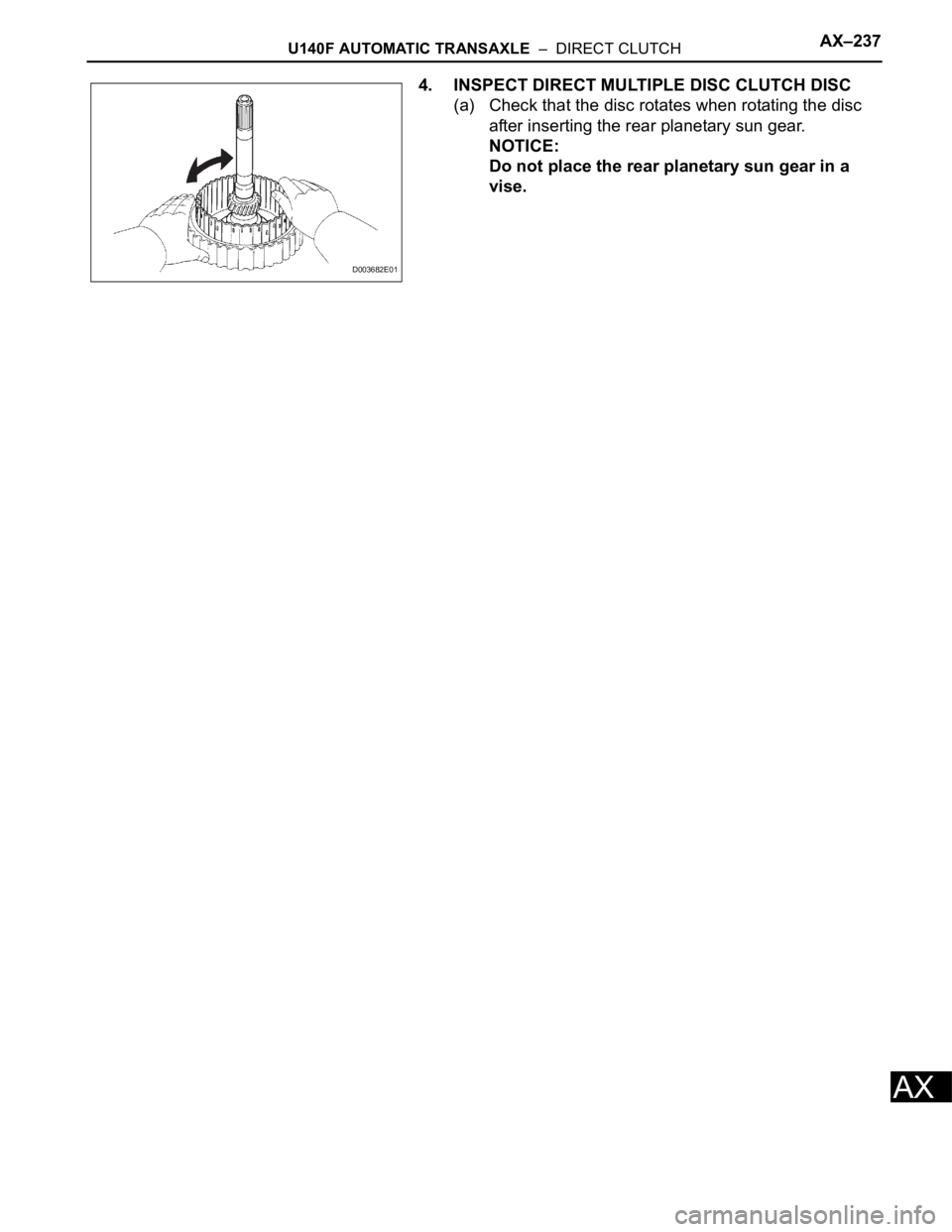
4. INSPECT DIRECT MULTIPLE DISC CLUTCH DISC
(a) Check that the disc rotates when rotating the disc
after inserting the rear planetary sun gear.
NOTICE:
Do not place the rear planetary sun gear in a
vise.
D003682E01
Page 1017 of 2000
U140F AUTOMATIC TRANSAXLE – DIFFERENTIAL CASEAX–257
AX
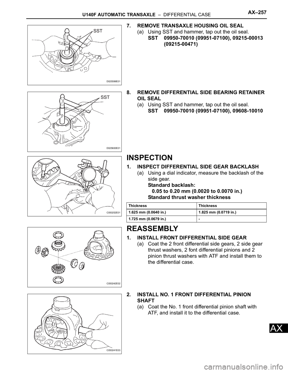
7. REMOVE TRANSAXLE HOUSING OIL SEAL
(a) Using SST and hammer, tap out the oil seal.
SST 09950-70010 (09951-07100), 09215-00013
(09215-00471)
8. REMOVE DIFFERENTIAL SIDE BEARING RETAINER
OIL SEAL
(a) Using SST and hammer, tap out the oil seal.
SST 09950-70010 (09951-07100), 09608-10010
INSPECTION
1. INSPECT DIFFERENTIAL SIDE GEAR BACKLASH
(a) Using a dial indicator, measure the backlash of the
side gear.
Standard backlash:
0.05 to 0.20 mm (0.0020 to 0.0070 in.)
Standard thrust washer thickness
REASSEMBLY
1. INSTALL FRONT DIFFERENTIAL SIDE GEAR
(a) Coat the 2 front differential side gears, 2 side gear
thrust washers, 2 font differential pinions and 2
pinion thrust washers with ATF and install them to
the differential case.
2. INSTALL NO. 1 FRONT DIFFERENTIAL PINION
SHAFT
(a) Coat the No. 1 front differential pinion shaft with
ATF, and install it to the differential case.
D025599E01
D025600E01
C050252E01
Thickness Thickness
1.625 mm (0.0640 in.) 1.825 mm (0.0719 in.)
1.725 mm (0.0679 in.) -
C050242E02
C050241E03
Page 1018 of 2000
AX–258U140F AUTOMATIC TRANSAXLE – DIFFERENTIAL CASE
AX
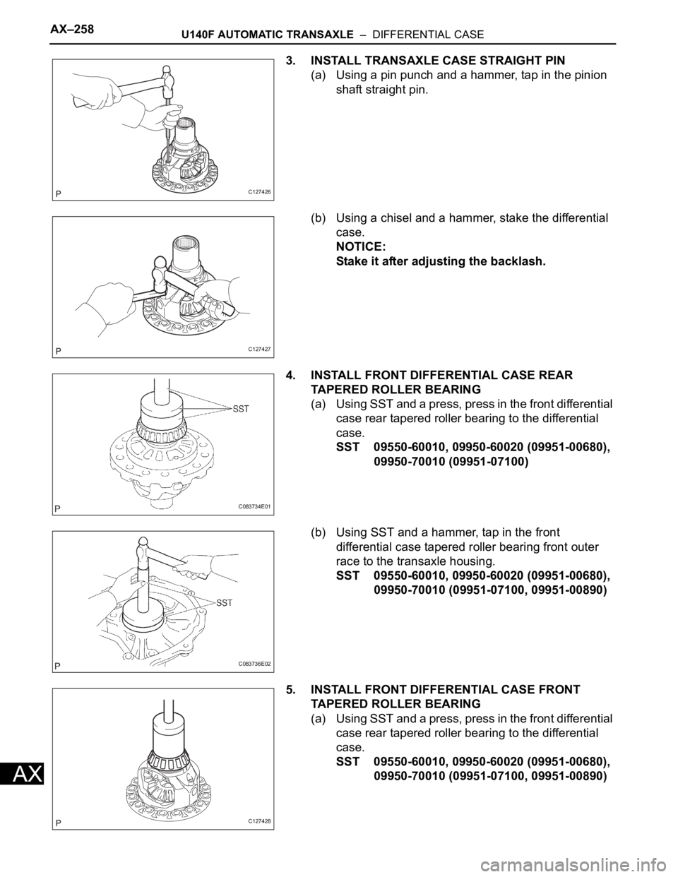
3. INSTALL TRANSAXLE CASE STRAIGHT PIN
(a) Using a pin punch and a hammer, tap in the pinion
shaft straight pin.
(b) Using a chisel and a hammer, stake the differential
case.
NOTICE:
Stake it after adjusting the backlash.
4. INSTALL FRONT DIFFERENTIAL CASE REAR
TAPERED ROLLER BEARING
(a) U si ng SST and a pres s, pr es s in the f ron t di fferent ial
case rear tapered roller bearing to the differential
case.
SST 09550-60010, 09950-60020 (09951-00680),
09950-70010 (09951-07100)
(b) Using SST and a hammer, tap in the front
differential case tapered roller bearing front outer
race to the transaxle housing.
SST 09550-60010, 09950-60020 (09951-00680),
09950-70010 (09951-07100, 09951-00890)
5. INSTALL FRONT DIFFERENTIAL CASE FRONT
TAPERED ROLLER BEARING
(a) Using SST and a press, press in the front differential
case rear tapered roller bearing to the differential
case.
SST 09550-60010, 09950-60020 (09951-00680),
09950-70010 (09951-07100, 09951-00890)
C127426
C127427
C083734E01
C083736E02
C127428
Page 1019 of 2000
U140F AUTOMATIC TRANSAXLE – DIFFERENTIAL CASEAX–259
AX
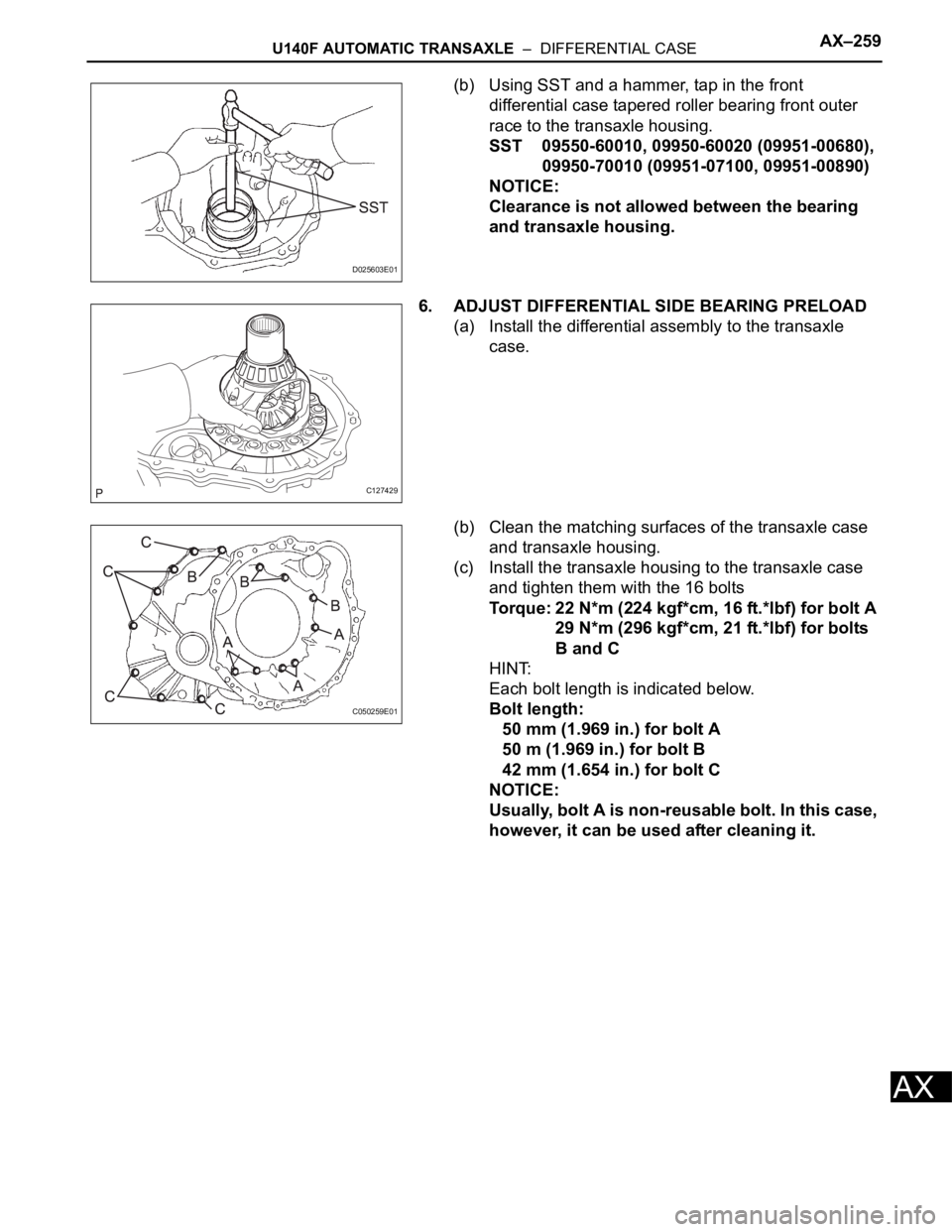
(b) Using SST and a hammer, tap in the front
differential case tapered roller bearing front outer
race to the transaxle housing.
SST 09550-60010, 09950-60020 (09951-00680),
09950-70010 (09951-07100, 09951-00890)
NOTICE:
Clearance is not allowed between the bearing
and transaxle housing.
6. ADJUST DIFFERENTIAL SIDE BEARING PRELOAD
(a) Install the differential assembly to the transaxle
case.
(b) Clean the matching surfaces of the transaxle case
and transaxle housing.
(c) Install the transaxle housing to the transaxle case
and tighten them with the 16 bolts
Torque: 22 N*m (224 kgf*cm, 16 ft.*lbf) for bolt A
29 N*m (296 kgf*cm, 21 ft.*lbf) for bolts
B and C
HINT:
Each bolt length is indicated below.
Bolt length:
50 mm (1.969 in.) for bolt A
50 m (1.969 in.) for bolt B
42 mm (1.654 in.) for bolt C
NOTICE:
Usually, bolt A is non-reusable bolt. In this case,
however, it can be used after cleaning it.
D025603E01
C127429
C050259E01
Page 1020 of 2000
AX–260U140F AUTOMATIC TRANSAXLE – DIFFERENTIAL CASE
AX
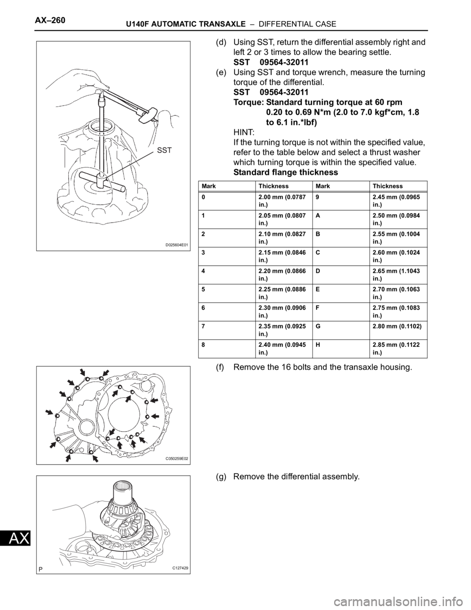
(d) Using SST, return the differential assembly right and
left 2 or 3 times to allow the bearing settle.
SST 09564-32011
(e) Using SST and torque wrench, measure the turning
torque of the differential.
SST 09564-32011
Torque: Standard turning torque at 60 rpm
0.20 to 0.69 N*m (2.0 to 7.0 kgf*cm, 1.8
to 6.1 in.*lbf)
HINT:
If the turning torque is not within the specified value,
refer to the table below and select a thrust washer
which turning torque is within the specified value.
Standard flange thickness
(f) Remove the 16 bolts and the transaxle housing.
(g) Remove the differential assembly.
D025604E01
Mark Thickness Mark Thickness
0 2.00 mm (0.0787
in.)9 2.45 mm (0.0965
in.)
1 2.05 mm (0.0807
in.)A 2.50 mm (0.0984
in.)
2 2.10 mm (0.0827
in.)B 2.55 mm (0.1004
in.)
3 2.15 mm (0.0846
in.)C 2.60 mm (0.1024
in.)
4 2.20 mm (0.0866
in.)D 2.65 mm (1.1043
in.)
5 2.25 mm (0.0886
in.)E 2.70 mm (0.1063
in.)
6 2.30 mm (0.0906
in.)F 2.75 mm (0.1083
in.)
7 2.35 mm (0.0925
in.)G 2.80 mm (0.1102)
8 2.40 mm (0.0945
in.)H 2.85 mm (0.1122
in.)
C050259E02
C127429