TOYOTA RAV4 2006 Service Repair Manual
Manufacturer: TOYOTA, Model Year: 2006, Model line: RAV4, Model: TOYOTA RAV4 2006Pages: 2000, PDF Size: 45.84 MB
Page 1161 of 2000
AX–168U151F AUTOMATIC TRANSAXLE – FLOOR SHIFT ASSEMBLY
AX
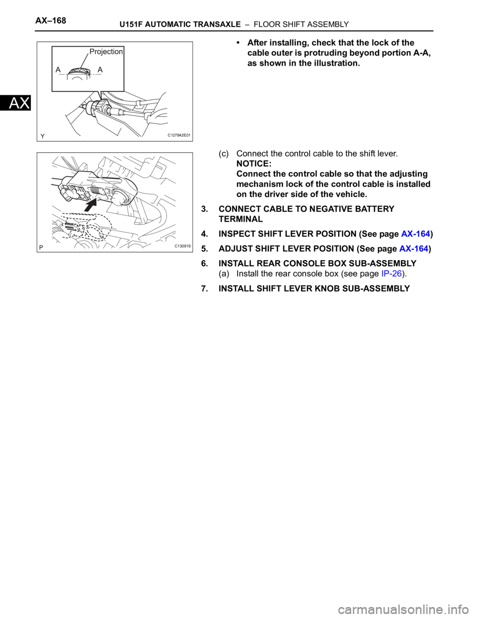
• After installing, check that the lock of the
cable outer is protruding beyond portion A-A,
as shown in the illustration.
(c) Connect the control cable to the shift lever.
NOTICE:
Connect the control cable so that the adjusting
mechanism lock of the control cable is installed
on the driver side of the vehicle.
3. CONNECT CABLE TO NEGATIVE BATTERY
TERMINAL
4. INSPECT SHIFT LEVER POSITION (See page AX-164)
5. ADJUST SHIFT LEVER POSITION (See page AX-164)
6. INSTALL REAR CONSOLE BOX SUB-ASSEMBLY
(a) Install the rear console box (see page IP-26).
7. INSTALL SHIFT LEVER KNOB SUB-ASSEMBLY
C127842E01
C130919
Page 1162 of 2000
AX–170U151F AUTOMATIC TRANSAXLE – DIFFERENTIAL OIL SEAL
AX
REPLACEMENT
1. REPLACE TRANSAXLE HOUSING OIL SEAL LH
(a) Drain the automatic transaxle fluid.
(1) Remove the drain plug and gasket, and drain
the ATF.
(2) Install a new gasket and drain plug.
Torque: 47 N*m (479 kgf*cm, 35 ft.*lbf)
(b) Remove the front drive shaft LH (see page DS-41).
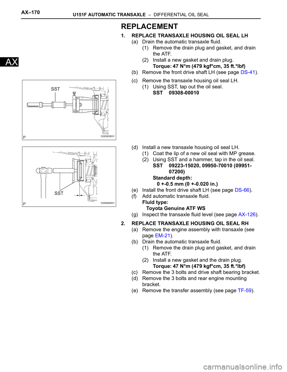
(c) Remove the transaxle housing oil seal LH.
(1) Using SST, tap out the oil seal.
SST 09308-00010
(d) Install a new transaxle housing oil seal LH.
(1) Coat the lip of a new oil seal with MP grease.
(2) Using SST and a hammer, tap in the oil seal.
SST 09223-15020, 09950-70010 (09951-
07200)
Standard depth:
0 +-0.5 mm (0 +-0.020 in.)
(e) Install the front drive shaft LH (see page DS-66).
(f) Add automatic transaxle fluid.
Fluid type:
Toyota Genuine ATF WS
(g) Inspect the transaxle fluid level (see page AX-126).
2. REPLACE TRANSAXLE HOUSING OIL SEAL RH
(a) Remove the engine assembly with transaxle (see
page EM-21).
(b) Drain the automatic transaxle fluid.
(1) Remove the drain plug and gasket, and drain
the ATF.
(2) Install a new gasket and the drain plug.
Torque: 47 N*m (479 kgf*cm, 35 ft.*lbf)
(c) Remove the 3 bolts and drive shaft bearing bracket.
(d) Remove the 3 bolts and rear engine mounting
bracket.
(e) Remove the transfer assembly (see page TF-59).
D025835E01
D025836E01
Page 1163 of 2000
U151F AUTOMATIC TRANSAXLE – DIFFERENTIAL OIL SEALAX–171
AX
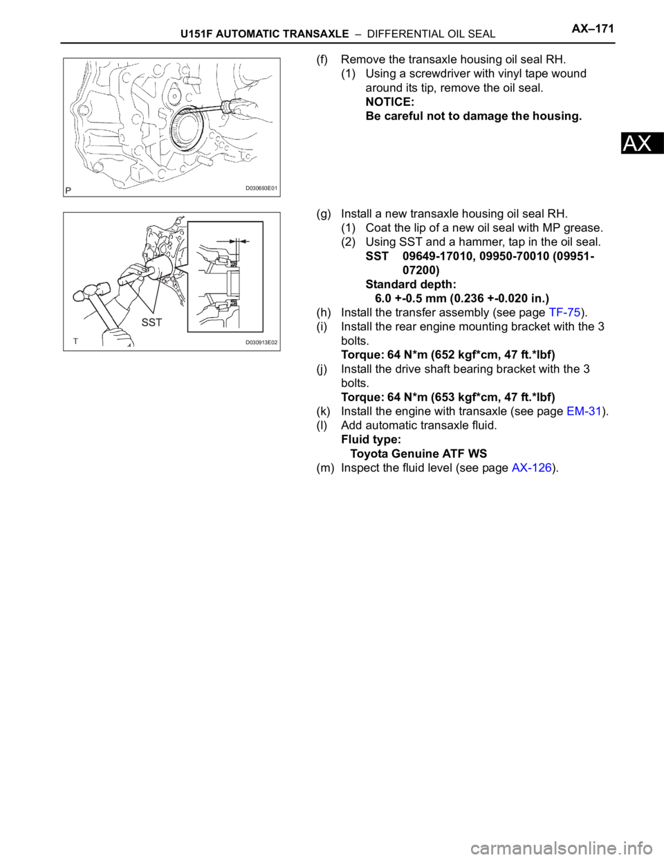
(f) Remove the transaxle housing oil seal RH.
(1) Using a screwdriver with vinyl tape wound
around its tip, remove the oil seal.
NOTICE:
Be careful not to damage the housing.
(g) Install a new transaxle housing oil seal RH.
(1) Coat the lip of a new oil seal with MP grease.
(2) Using SST and a hammer, tap in the oil seal.
SST 09649-17010, 09950-70010 (09951-
07200)
Standard depth:
6.0 +-0.5 mm (0.236 +-0.020 in.)
(h) Install the transfer assembly (see page TF-75).
(i) Install the rear engine mounting bracket with the 3
bolts.
Torque: 64 N*m (652 kgf*cm, 47 ft.*lbf)
(j) Install the drive shaft bearing bracket with the 3
bolts.
Torque: 64 N*m (653 kgf*cm, 47 ft.*lbf)
(k) Install the engine with transaxle (see page EM-31).
(l) Add automatic transaxle fluid.
Fluid type:
Toyota Genuine ATF WS
(m) Inspect the fluid level (see page AX-126).
D030693E01
D030913E02
Page 1164 of 2000
AX–176U151F AUTOMATIC TRANSAXLE – AUTOMATIC TRANSAXLE ASSEMBLY
AX
INSTALLATION
1. INSPECT TORQUE CONVERTER CLUTCH
ASSEMBLY
(a) Inspect the torque converter clutch (see page AX-
179).
2. INSTALL TORQUE CONVERTER CLUTCH
ASSEMBLY
(a) Install the torque converter clutch to the automatic
transaxle.
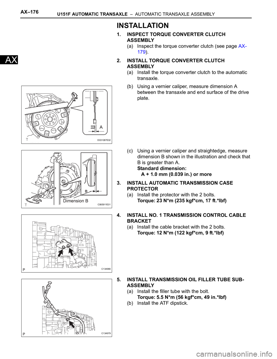
(b) Using a vernier caliper, measure dimension A
between the transaxle and end surface of the drive
plate.
(c) Using a vernier caliper and straightedge, measure
dimension B shown in the illustration and check that
B is greater than A.
Standard dimension:
A + 1.0 mm (0.039 in.) or more
3. INSTALL AUTOMATIC TRANSMISSION CASE
PROTECTOR
(a) Install the protector with the 2 bolts.
Torque: 23 N*m (235 kgf*cm, 17 ft.*lbf)
4. INSTALL NO. 1 TRANSMISSION CONTROL CABLE
BRACKET
(a) Install the cable bracket with the 2 bolts.
Torque: 12 N*m (122 kgf*cm, 9 ft.*lbf)
5. INSTALL TRANSMISSION OIL FILLER TUBE SUB-
ASSEMBLY
(a) Install the filler tube with the bolt.
Torque: 5.5 N*m (56 kgf*cm, 49 in.*lbf)
(b) Install the ATF dipstick.
D031087E02
C065911E01
C134980
C134979
Page 1165 of 2000
U151F AUTOMATIC TRANSAXLE – AUTOMATIC TRANSAXLE ASSEMBLYAX–177
AX
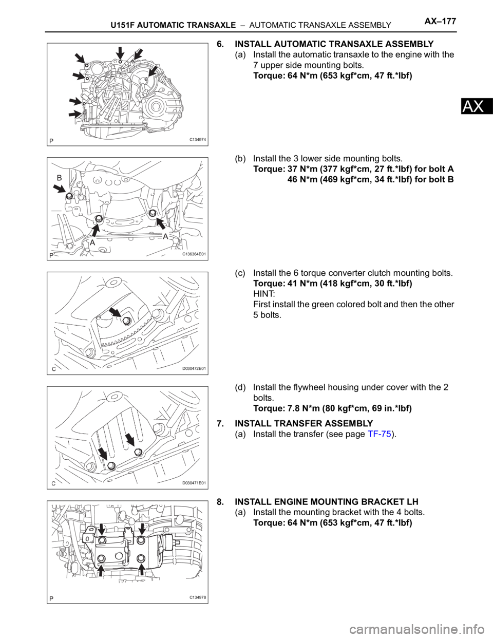
6. INSTALL AUTOMATIC TRANSAXLE ASSEMBLY
(a) Install the automatic transaxle to the engine with the
7 upper side mounting bolts.
Torque: 64 N*m (653 kgf*cm, 47 ft.*lbf)
(b) Install the 3 lower side mounting bolts.
Torque: 37 N*m (377 kgf*cm, 27 ft.*lbf) for bolt A
46 N*m (469 kgf*cm, 34 ft.*lbf) for bolt B
(c) Install the 6 torque converter clutch mounting bolts.
Torque: 41 N*m (418 kgf*cm, 30 ft.*lbf)
HINT:
First install the green colored bolt and then the other
5 bolts.
(d) Install the flywheel housing under cover with the 2
bolts.
Torque: 7.8 N*m (80 kgf*cm, 69 in.*lbf)
7. INSTALL TRANSFER ASSEMBLY
(a) Install the transfer (see page TF-75).
8. INSTALL ENGINE MOUNTING BRACKET LH
(a) Install the mounting bracket with the 4 bolts.
Torque: 64 N*m (653 kgf*cm, 47 ft.*lbf)
C134974
C136364E01
D030472E01
D030471E01
C134978
Page 1166 of 2000
AX–178U151F AUTOMATIC TRANSAXLE – AUTOMATIC TRANSAXLE ASSEMBLY
AX
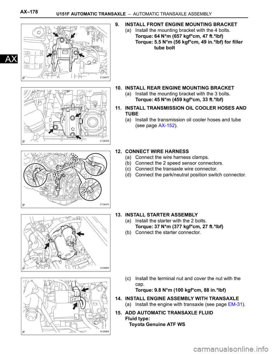
9. INSTALL FRONT ENGINE MOUNTING BRACKET
(a) Install the mounting bracket with the 4 bolts.
Torque: 64 N*m (657 kgf*cm, 47 ft.*lbf)
Torque: 5.5 N*m (56 kgf*cm, 49 in.*lbf) for filler
tube bolt
10. INSTALL REAR ENGINE MOUNTING BRACKET
(a) Install the mounting bracket with the 3 bolts.
Torque: 45 N*m (459 kgf*cm, 33 ft.*lbf)
11. INSTALL TRANSMISSION OIL COOLER HOSES AND
TUBE
(a) Install the transmission oil cooler hoses and tube
(see page AX-152).
12. CONNECT WIRE HARNESS
(a) Connect the wire harness clamps.
(b) Connect the 2 speed sensor connectors.
(c) Connect the transaxle wire connector.
(d) Connect the park/neutral position switch connector.
13. INSTALL STARTER ASSEMBLY
(a) Install the starter with the 2 bolts.
Torque: 37 N*m (377 kgf*cm, 27 ft.*lbf)
(b) Connect the starter connector.
(c) Install the terminal nut and cover the nut with the
cap.
Torque: 9.8 N*m (100 kgf*cm, 88 in.*lbf)
14. INSTALL ENGINE ASSEMBLY WITH TRANSAXLE
(a) Install the engine with transaxle (see page EM-31).
15. ADD AUTOMATIC TRANSAXLE FLUID
Fluid type:
Toyota Genuine ATF WS
C134977
C134976
C134973
A126955
A126954
Page 1167 of 2000

U151F AUTOMATIC TRANSAXLE – AUTOMATIC TRANSAXLE ASSEMBLYAX–179
AX
16. INSPECT AUTOMATIC TRANSAXLE FLUID
(a) Inspect the automatic transaxle fluid (see page AX-
126).
17. PERFORM RESET MEMORY
(a) Perform the RESET MEMORY procedures (A/T
initialization) (see page AX-20).
Page 1168 of 2000
AX–190U151F AUTOMATIC TRANSAXLE – AUTOMATIC TRANSAXLE UNIT
AX
DISASSEMBLY
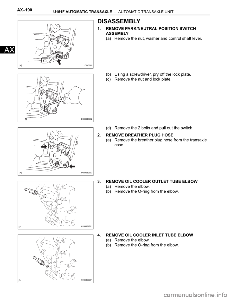
1. REMOVE PARK/NEUTRAL POSITION SWITCH
ASSEMBLY
(a) Remove the nut, washer and control shaft lever.
(b) Using a screwdriver, pry off the lock plate.
(c) Remove the nut and lock plate.
(d) Remove the 2 bolts and pull out the switch.
2. REMOVE BREATHER PLUG HOSE
(a) Remove the breather plug hose from the transaxle
case.
3. REMOVE OIL COOLER OUTLET TUBE ELBOW
(a) Remove the elbow.
(b) Remove the O-ring from the elbow.
4. REMOVE OIL COOLER INLET TUBE ELBOW
(a) Remove the elbow.
(b) Remove the O-ring from the elbow.
C140280
D009643E02
D009639E02
C136351E01
C136352E01
Page 1169 of 2000
U151F AUTOMATIC TRANSAXLE – AUTOMATIC TRANSAXLE UNITAX–191
AX
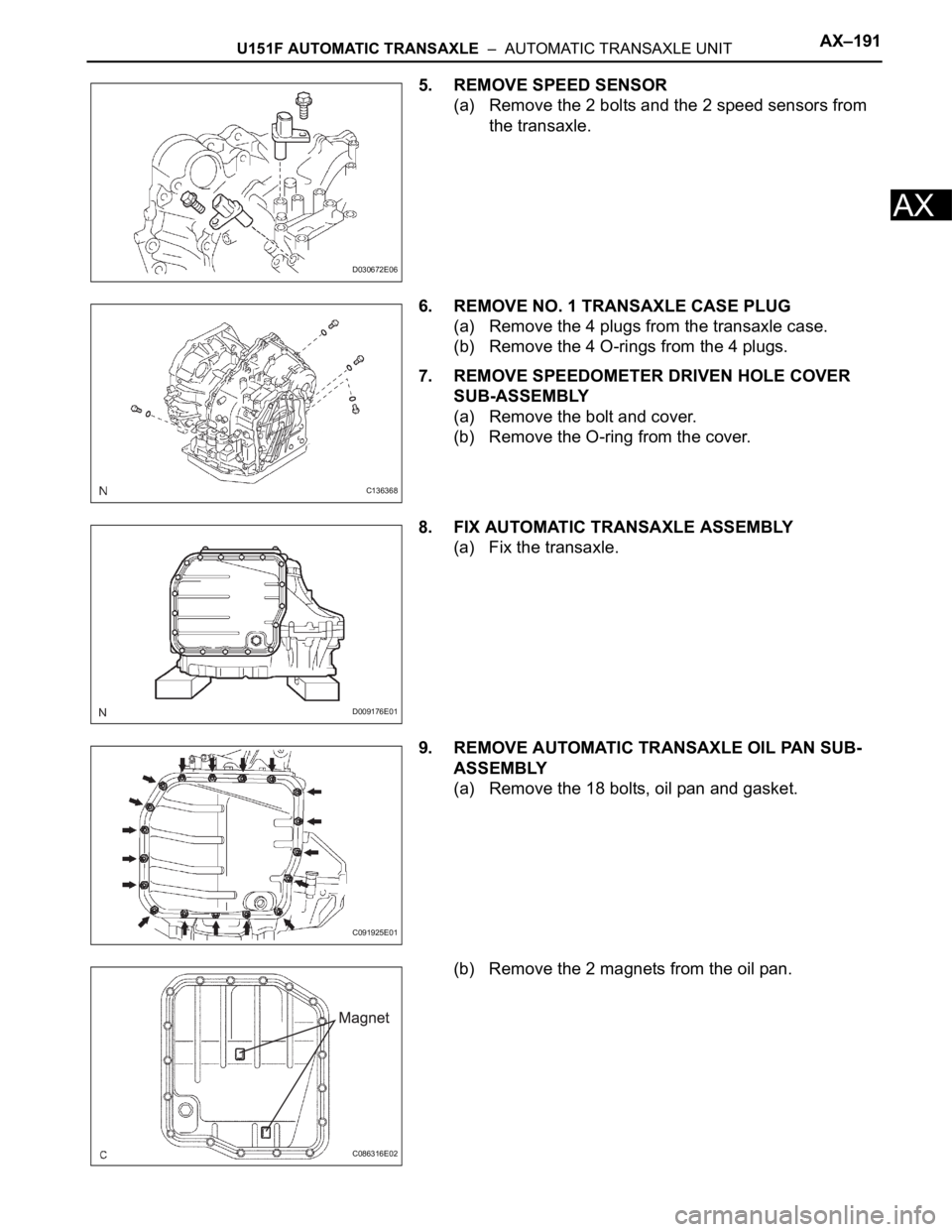
5. REMOVE SPEED SENSOR
(a) Remove the 2 bolts and the 2 speed sensors from
the transaxle.
6. REMOVE NO. 1 TRANSAXLE CASE PLUG
(a) Remove the 4 plugs from the transaxle case.
(b) Remove the 4 O-rings from the 4 plugs.
7. REMOVE SPEEDOMETER DRIVEN HOLE COVER
SUB-ASSEMBLY
(a) Remove the bolt and cover.
(b) Remove the O-ring from the cover.
8. FIX AUTOMATIC TRANSAXLE ASSEMBLY
(a) Fix the transaxle.
9. REMOVE AUTOMATIC TRANSAXLE OIL PAN SUB-
ASSEMBLY
(a) Remove the 18 bolts, oil pan and gasket.
(b) Remove the 2 magnets from the oil pan.
D030672E06
C136368
D009176E01
C091925E01
C086316E02
Page 1170 of 2000
AX–192U151F AUTOMATIC TRANSAXLE – AUTOMATIC TRANSAXLE UNIT
AX
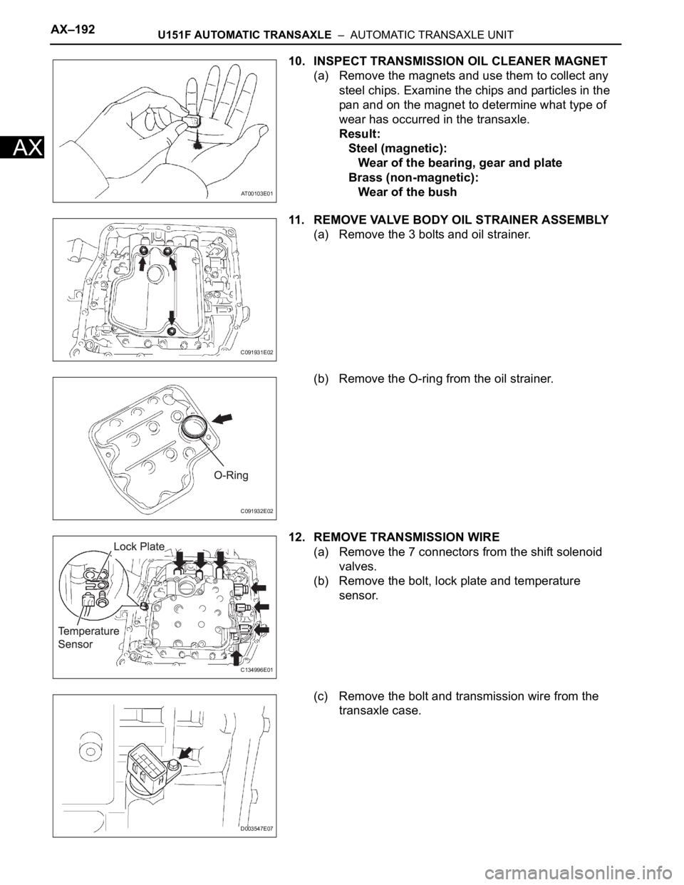
10. INSPECT TRANSMISSION OIL CLEANER MAGNET
(a) Remove the magnets and use them to collect any
steel chips. Examine the chips and particles in the
pan and on the magnet to determine what type of
wear has occurred in the transaxle.
Result:
Steel (magnetic):
Wear of the bearing, gear and plate
Brass (non-magnetic):
Wear of the bush
11. REMOVE VALVE BODY OIL STRAINER ASSEMBLY
(a) Remove the 3 bolts and oil strainer.
(b) Remove the O-ring from the oil strainer.
12. REMOVE TRANSMISSION WIRE
(a) Remove the 7 connectors from the shift solenoid
valves.
(b) Remove the bolt, lock plate and temperature
sensor.
(c) Remove the bolt and transmission wire from the
transaxle case.
AT00103E01
C091931E02
C091932E02
C134996E01
D003547E07