TOYOTA RAV4 2006 Service Repair Manual
Manufacturer: TOYOTA, Model Year: 2006, Model line: RAV4, Model: TOYOTA RAV4 2006Pages: 2000, PDF Size: 45.84 MB
Page 1311 of 2000
U241E AUTOMATIC TRANSAXLE – AUTOMATIC TRANSAXLE UNITAX–207
AX
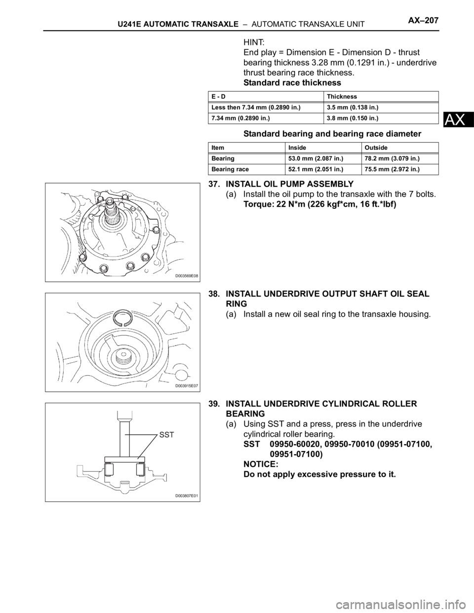
HINT:
End play = Dimension E - Dimension D - thrust
bearing thickness 3.28 mm (0.1291 in.) - underdrive
thrust bearing race thickness.
Standard race thickness
Standard bearing and bearing race diameter
37. INSTALL OIL PUMP ASSEMBLY
(a) Install the oil pump to the transaxle with the 7 bolts.
Torque: 22 N*m (226 kgf*cm, 16 ft.*lbf)
38. INSTALL UNDERDRIVE OUTPUT SHAFT OIL SEAL
RING
(a) Install a new oil seal ring to the transaxle housing.
39. INSTALL UNDERDRIVE CYLINDRICAL ROLLER
BEARING
(a) Using SST and a press, press in the underdrive
cylindrical roller bearing.
SST 09950-60020, 09950-70010 (09951-07100,
09951-07100)
NOTICE:
Do not apply excessive pressure to it.
E - D Thickness
Less then 7.34 mm (0.2890 in.) 3.5 mm (0.138 in.)
7.34 mm (0.2890 in.) 3.8 mm (0.150 in.)
Item Inside Outside
Bearing 53.0 mm (2.087 in.) 78.2 mm (3.079 in.)
Bearing race 52.1 mm (2.051 in.) 75.5 mm (2.972 in.)
D003569E08
D003915E07
D003807E01
Page 1312 of 2000
AX–208U241E AUTOMATIC TRANSAXLE – AUTOMATIC TRANSAXLE UNIT
AX
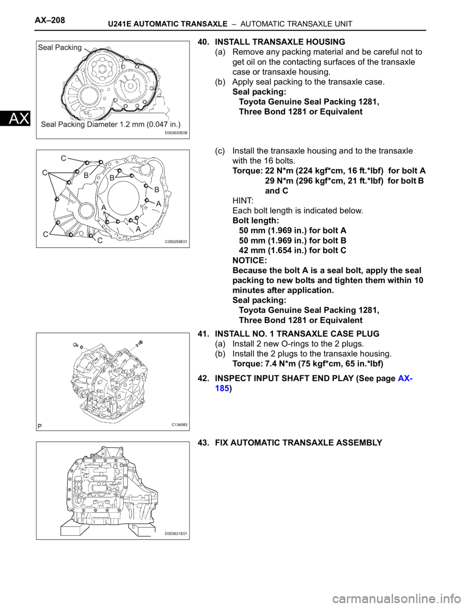
40. INSTALL TRANSAXLE HOUSING
(a) Remove any packing material and be careful not to
get oil on the contacting surfaces of the transaxle
case or transaxle housing.
(b) Apply seal packing to the transaxle case.
Seal packing:
Toyota Genuine Seal Packing 1281,
Three Bond 1281 or Equivalent
(c) Install the transaxle housing and to the transaxle
with the 16 bolts.
Torque: 22 N*m (224 kgf*cm, 16 ft.*lbf) for bolt A
29 N*m (296 kgf*cm, 21 ft.*lbf) for bolt B
and C
HINT:
Each bolt length is indicated below.
Bolt length:
50 mm (1.969 in.) for bolt A
50 mm (1.969 in.) for bolt B
42 mm (1.654 in.) for bolt C
NOTICE:
Because the bolt A is a seal bolt, apply the seal
packing to new bolts and tighten them within 10
minutes after application.
Seal packing:
Toyota Genuine Seal Packing 1281,
Three Bond 1281 or Equivalent
41. INSTALL NO. 1 TRANSAXLE CASE PLUG
(a) Install 2 new O-rings to the 2 plugs.
(b) Install the 2 plugs to the transaxle housing.
Torque: 7.4 N*m (75 kgf*cm, 65 in.*lbf)
42. INSPECT INPUT SHAFT END PLAY (See page AX-
185)
43. FIX AUTOMATIC TRANSAXLE ASSEMBLY
D003630E08
C050259E01
C134983
D003631E01
Page 1313 of 2000
U241E AUTOMATIC TRANSAXLE – AUTOMATIC TRANSAXLE UNITAX–209
AX
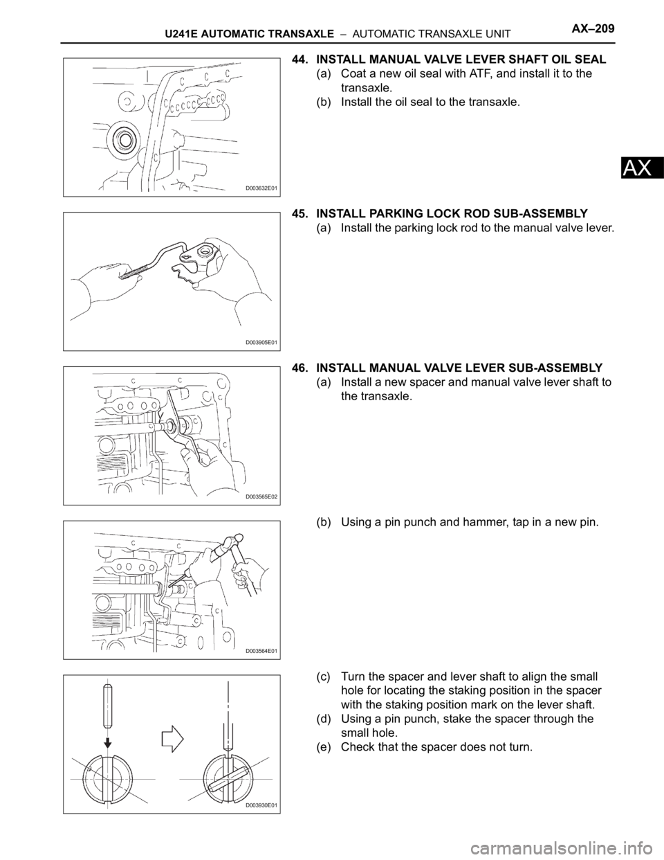
44. INSTALL MANUAL VALVE LEVER SHAFT OIL SEAL
(a) Coat a new oil seal with ATF, and install it to the
transaxle.
(b) Install the oil seal to the transaxle.
45. INSTALL PARKING LOCK ROD SUB-ASSEMBLY
(a) Install the parking lock rod to the manual valve lever.
46. INSTALL MANUAL VALVE LEVER SUB-ASSEMBLY
(a) Install a new spacer and manual valve lever shaft to
the transaxle.
(b) Using a pin punch and hammer, tap in a new pin.
(c) Turn the spacer and lever shaft to align the small
hole for locating the staking position in the spacer
with the staking position mark on the lever shaft.
(d) Using a pin punch, stake the spacer through the
small hole.
(e) Check that the spacer does not turn.
D003632E01
D003905E01
D003565E02
D003564E01
D003930E01
Page 1314 of 2000
AX–210U241E AUTOMATIC TRANSAXLE – AUTOMATIC TRANSAXLE UNIT
AX
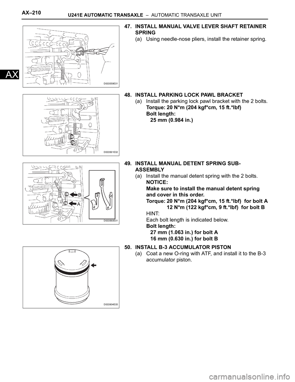
47. INSTALL MANUAL VALVE LEVER SHAFT RETAINER
SPRING
(a) Using needle-nose pliers, install the retainer spring.
48. INSTALL PARKING LOCK PAWL BRACKET
(a) Install the parking lock pawl bracket with the 2 bolts.
Torque: 20 N*m (204 kgf*cm, 15 ft.*lbf)
Bolt length:
25 mm (0.984 in.)
49. INSTALL MANUAL DETENT SPRING SUB-
ASSEMBLY
(a) Install the manual detent spring with the 2 bolts.
NOTICE:
Make sure to install the manual detent spring
and cover in this order.
Torque: 20 N*m (204 kgf*cm, 15 ft.*lbf) for bolt A
12 N*m (122 kgf*cm, 9 ft.*lbf) for bolt B
HINT:
Each bolt length is indicated below.
Bolt length:
27 mm (1.063 in.) for bolt A
16 mm (0.630 in.) for bolt B
50. INSTALL B-3 ACCUMULATOR PISTON
(a) Coat a new O-ring with ATF, and install it to the B-3
accumulator piston.
D003559E01
D003561E02
D003560E01
D003904E05
Page 1315 of 2000
U241E AUTOMATIC TRANSAXLE – AUTOMATIC TRANSAXLE UNITAX–211
AX
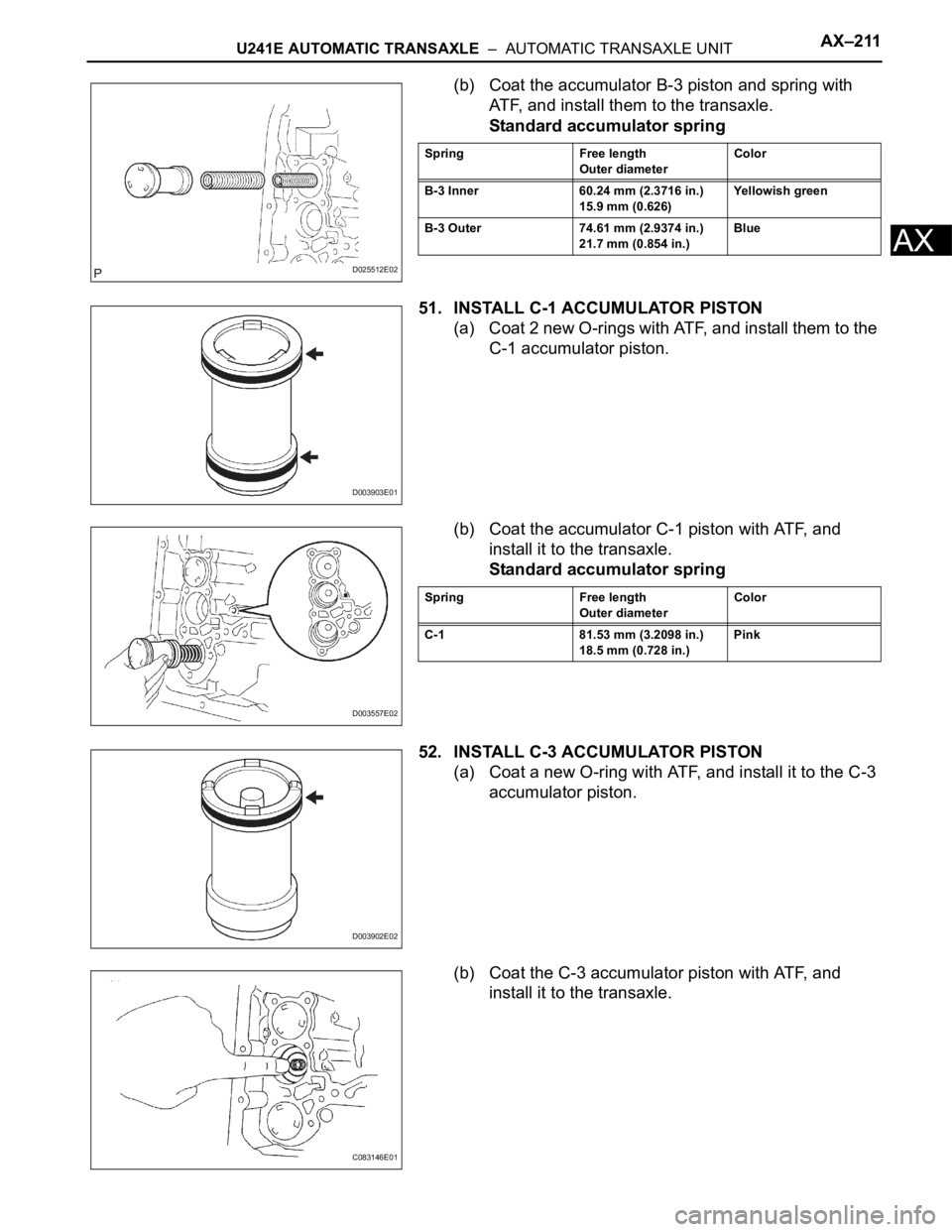
(b) Coat the accumulator B-3 piston and spring with
ATF, and install them to the transaxle.
Standard accumulator spring
51. INSTALL C-1 ACCUMULATOR PISTON
(a) Coat 2 new O-rings with ATF, and install them to the
C-1 accumulator piston.
(b) Coat the accumulator C-1 piston with ATF, and
install it to the transaxle.
Standard accumulator spring
52. INSTALL C-3 ACCUMULATOR PISTON
(a) Coat a new O-ring with ATF, and install it to the C-3
accumulator piston.
(b) Coat the C-3 accumulator piston with ATF, and
install it to the transaxle.
D025512E02
Spring Free length
Outer diameterColor
B-3 Inner 60.24 mm (2.3716 in.)
15.9 mm (0.626)Yellowish green
B-3 Outer 74.61 mm (2.9374 in.)
21.7 mm (0.854 in.)Blue
D003903E01
D003557E02
Spring Free length
Outer diameterColor
C-1 81.53 mm (3.2098 in.)
18.5 mm (0.728 in.)Pink
D003902E02
C083146E01
Page 1316 of 2000
AX–212U241E AUTOMATIC TRANSAXLE – AUTOMATIC TRANSAXLE UNIT
AX
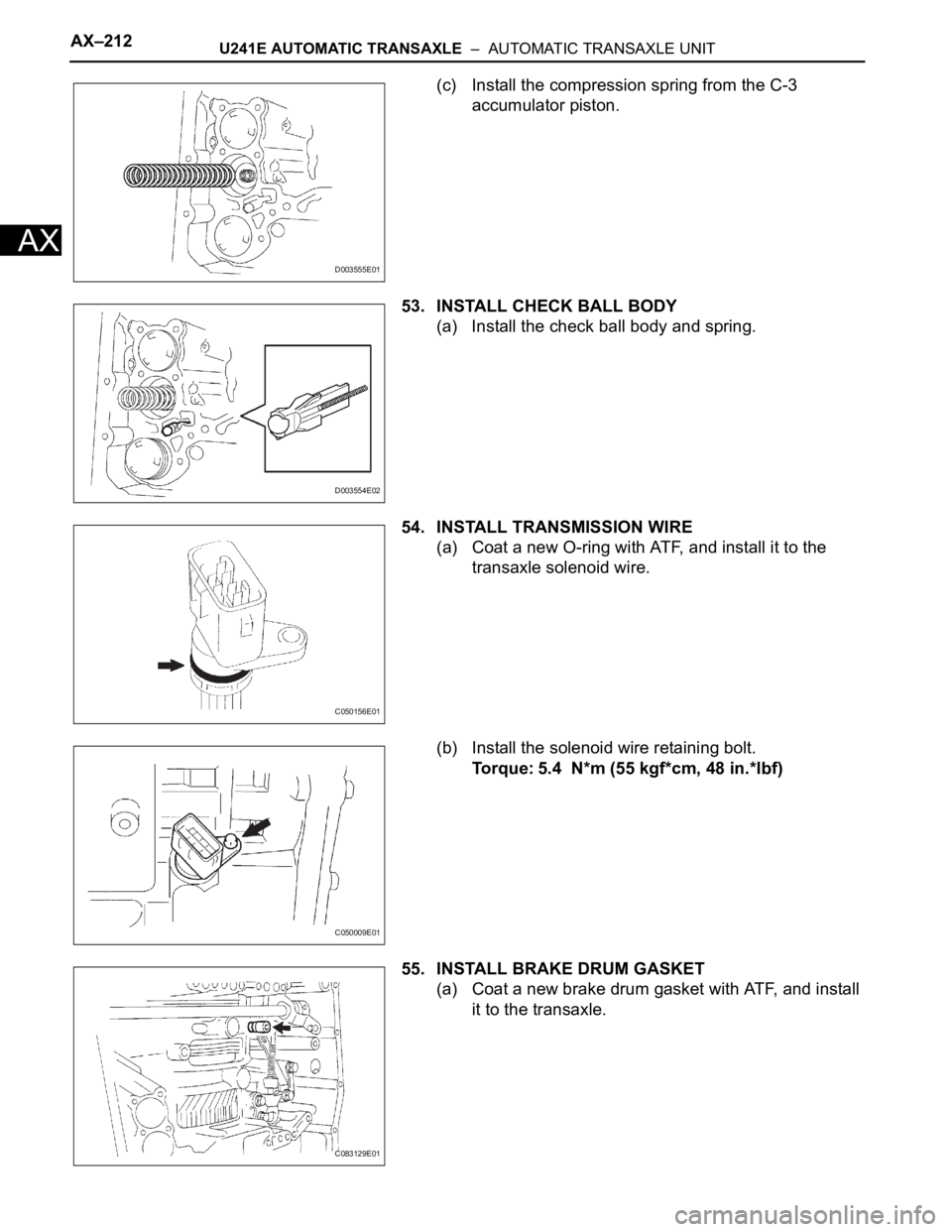
(c) Install the compression spring from the C-3
accumulator piston.
53. INSTALL CHECK BALL BODY
(a) Install the check ball body and spring.
54. INSTALL TRANSMISSION WIRE
(a) Coat a new O-ring with ATF, and install it to the
transaxle solenoid wire.
(b) Install the solenoid wire retaining bolt.
Torque: 5.4 N*m (55 kgf*cm, 48 in.*lbf)
55. INSTALL BRAKE DRUM GASKET
(a) Coat a new brake drum gasket with ATF, and install
it to the transaxle.
D003555E01
D003554E02
C050156E01
C050009E01
C083129E01
Page 1317 of 2000
U241E AUTOMATIC TRANSAXLE – AUTOMATIC TRANSAXLE UNITAX–213
AX
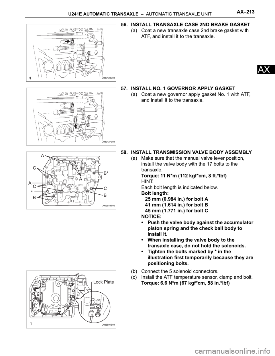
56. INSTALL TRANSAXLE CASE 2ND BRAKE GASKET
(a) Coat a new transaxle case 2nd brake gasket with
ATF, and install it to the transaxle.
57. INSTALL NO. 1 GOVERNOR APPLY GASKET
(a) Coat a new governor apply gasket No. 1 with ATF,
and install it to the transaxle.
58. INSTALL TRANSMISSION VALVE BODY ASSEMBLY
(a) Make sure that the manual valve lever position,
install the valve body with the 17 bolts to the
transaxle.
Torque: 11 N*m (112 kgf*cm, 8 ft.*lbf)
HINT:
Each bolt length is indicated below.
Bolt length:
25 mm (0.984 in.) for bolt A
41 mm (1.614 in.) for bolt B
45 mm (1.771 in.) for bolt C
NOTICE:
• Push the valve body against the accumulator
piston spring and the check ball body to
install it.
• When installing the valve body to the
transaxle case, do not hold the solenoids.
• Tighten the bolts marked by * in the
illustration first temporarily because they are
positioning bolts.
(b) Connect the 5 solenoid connectors.
(c) Install the ATF temperature sensor, clamp and bolt.
Torque: 6.6 N*m (67 kgf*cm, 58 in.*lbf)
C083128E01
C083127E01
D003553E09
D025591E01
Page 1318 of 2000
AX–214U241E AUTOMATIC TRANSAXLE – AUTOMATIC TRANSAXLE UNIT
AX
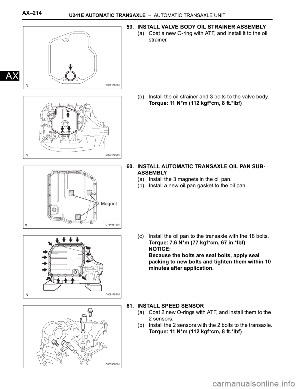
59. INSTALL VALVE BODY OIL STRAINER ASSEMBLY
(a) Coat a new O-ring with ATF, and install it to the oil
strainer.
(b) Install the oil strainer and 3 bolts to the valve body.
Torque: 11 N*m (112 kgf*cm, 8 ft.*lbf)
60. INSTALL AUTOMATIC TRANSAXLE OIL PAN SUB-
ASSEMBLY
(a) Install the 3 magnets in the oil pan.
(b) Install a new oil pan gasket to the oil pan.
(c) Install the oil pan to the transaxle with the 18 bolts.
Torque: 7.6 N*m (77 kgf*cm, 67 in.*lbf)
NOTICE:
Because the bolts are seal bolts, apply seal
packing to new bolts and tighten them within 10
minutes after application.
61. INSTALL SPEED SENSOR
(a) Coat 2 new O-rings with ATF, and install them to the
2 sensors.
(b) Install the 2 sensors with the 2 bolts to the transaxle.
Torque: 11 N*m (112 kgf*cm, 8 ft.*lbf)
D009180E01
D009179E01
C134981E01
D009176E02
D003900E01
Page 1319 of 2000
U241E AUTOMATIC TRANSAXLE – AUTOMATIC TRANSAXLE UNITAX–215
AX
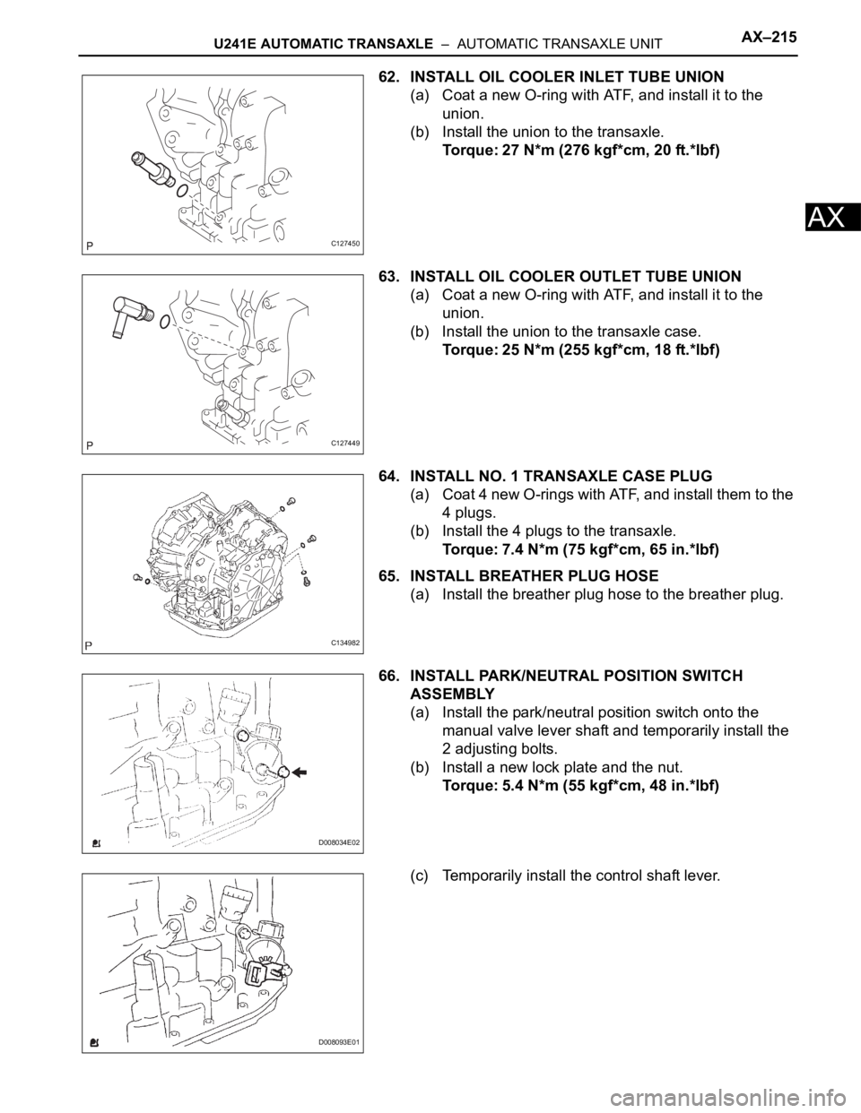
62. INSTALL OIL COOLER INLET TUBE UNION
(a) Coat a new O-ring with ATF, and install it to the
union.
(b) Install the union to the transaxle.
Torque: 27 N*m (276 kgf*cm, 20 ft.*lbf)
63. INSTALL OIL COOLER OUTLET TUBE UNION
(a) Coat a new O-ring with ATF, and install it to the
union.
(b) Install the union to the transaxle case.
Torque: 25 N*m (255 kgf*cm, 18 ft.*lbf)
64. INSTALL NO. 1 TRANSAXLE CASE PLUG
(a) Coat 4 new O-rings with ATF, and install them to the
4 plugs.
(b) Install the 4 plugs to the transaxle.
Torque: 7.4 N*m (75 kgf*cm, 65 in.*lbf)
65. INSTALL BREATHER PLUG HOSE
(a) Install the breather plug hose to the breather plug.
66. INSTALL PARK/NEUTRAL POSITION SWITCH
ASSEMBLY
(a) Install the park/neutral position switch onto the
manual valve lever shaft and temporarily install the
2 adjusting bolts.
(b) Install a new lock plate and the nut.
Torque: 5.4 N*m (55 kgf*cm, 48 in.*lbf)
(c) Temporarily install the control shaft lever.
C127450
C127449
C134982
D008034E02
D008093E01
Page 1320 of 2000
AX–216U241E AUTOMATIC TRANSAXLE – AUTOMATIC TRANSAXLE UNIT
AX
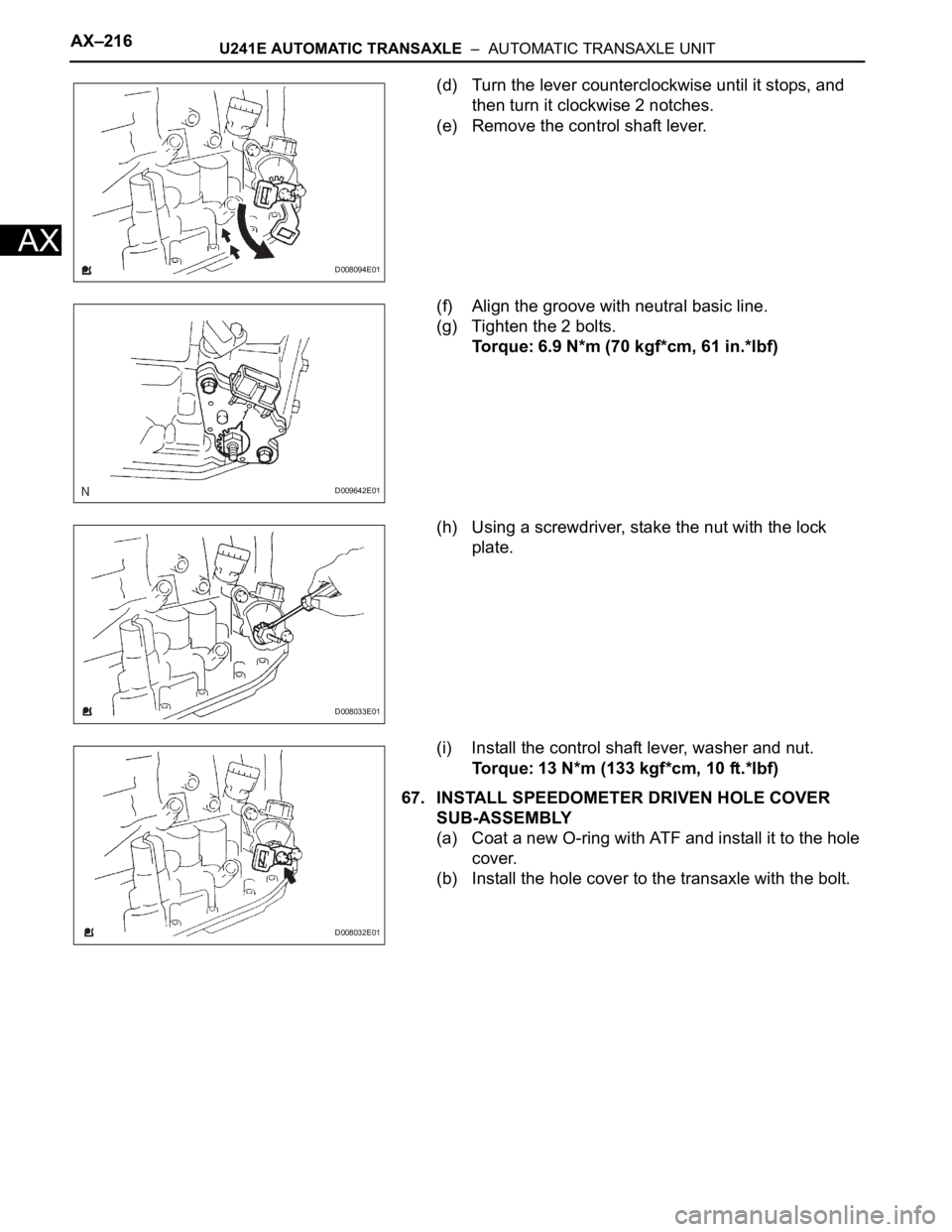
(d) Turn the lever counterclockwise until it stops, and
then turn it clockwise 2 notches.
(e) Remove the control shaft lever.
(f) Align the groove with neutral basic line.
(g) Tighten the 2 bolts.
Torque: 6.9 N*m (70 kgf*cm, 61 in.*lbf)
(h) Using a screwdriver, stake the nut with the lock
plate.
(i) Install the control shaft lever, washer and nut.
Torque: 13 N*m (133 kgf*cm, 10 ft.*lbf)
67. INSTALL SPEEDOMETER DRIVEN HOLE COVER
SUB-ASSEMBLY
(a) Coat a new O-ring with ATF and install it to the hole
cover.
(b) Install the hole cover to the transaxle with the bolt.
D008094E01
D009642E01
D008033E01
D008032E01