TOYOTA RAV4 2006 Service Repair Manual
Manufacturer: TOYOTA, Model Year: 2006, Model line: RAV4, Model: TOYOTA RAV4 2006Pages: 2000, PDF Size: 45.84 MB
Page 1961 of 2000
2AZ-FE ENGINE CONTROL SYSTEM – SFI SYSTEMES–73
ES
DESCRIPTION
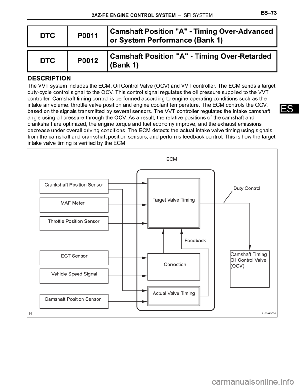
The VVT system includes the ECM, Oil Control Valve (OCV) and VVT controller. The ECM sends a target
duty-cycle control signal to the OCV. This control signal regulates the oil pressure supplied to the VVT
controller. Camshaft timing control is performed according to engine operating conditions such as the
intake air volume, throttle valve position and engine coolant temperature. The ECM controls the OCV,
based on the signals transmitted by several sensors. The VVT controller regulates the intake camshaft
angle using oil pressure through the OCV. As a result, the relative positions of the camshaft and
crankshaft are optimized, the engine torque and fuel economy improve, and the exhaust emissions
decrease under overall driving conditions. The ECM detects the actual intake valve timing using signals
from the camshaft and crankshaft position sensors, and performs feedback control. This is how the target
intake valve timing is verified by the ECM.
DTC P0011Camshaft Position "A" - Timing Over-Advanced
or System Performance (Bank 1)
DTC P0012Camshaft Position "A" - Timing Over-Retarded
(Bank 1)
A103843E08
Page 1962 of 2000

ES–742AZ-FE ENGINE CONTROL SYSTEM – SFI SYSTEM
ES
MONITOR DESCRIPTION
The ECM optimizes the intake valve timing using the VVT (Variable Valve Timing) system to control the
intake camshaft. The VVT system includes the ECM, the Oil Control Valve (OCV) and the VVT controller.
The ECM sends a target duty-cycle control signal to the OCV. This control signal regulates the oil
pressure supplied to the VVT controller. The VVT controller can advance or retard the intake camshaft.
If the difference between the target and actual intake valve timings is large, and changes in the actual
intake valve timing are small, the ECM interprets this as the VVT controller stuck malfunction and sets a
DTC.
Example:
A DTC is set when the following conditions 1, 2 and 3 are met:
1. The difference between the target and actual intake valve timing is more than 5
CA (Crankshaft
Angle) and the condition continues for more than 4.5 seconds.
2. It takes 5 seconds or more to change the valve timing by 5
CA.
3. After above conditions 1 and 2 are met, the OCV is forcibly activated 63 times or more.
DTC P0011 (Advanced Cam Timing) is subject to 1 trip detection logic.
DTC P0012 (Retarded Cam Timing) is subject to 2 trip detection logic.
These DTCs indicate that the VVT controller cannot operate properly due to OCV malfunctions or the
presence of foreign objects in the OCV.
The monitor will run if all of the following conditions are met:
– The engine is warm (the engine coolant temperature is 75
C [167F] or more).
– The vehicle has been driven at more than 64 km/h (40 mph) for 3 minutes.
– The engine has idled for 3 minutes.
MONITOR STRATEGY
DTC No. DTC Detection Conditions Trouble Areas
P0011Advanced camshaft timing:
With warm engine and engine speed of between 550 rpm and
4,000 rpm, all conditions (1), (2) and (3) met (1 trip detection
logic):
1. Difference between target and actual intake valve timings
more than 5
CA (Crankshaft Angle) for 4.5 seconds
2. Current intake valve timing fixed (timing changes less than
5
CA in 5 seconds)
3. Variations in VVT controller timing more than 19
CA of
maximum delayed timing (malfunction in advance timing)• Valve timing
•OCV
• OCV filter
• Camshaft timing gear assembly
•ECM
P0012Retarded camshaft timing:
With warm engine and engine speed of between 550 rpm and
4,000 rpm, all conditions (1), (2) and (3) met (2 trip detection
logic):
1. Difference between target and actual intake valve timings
more than 5
CA (Crankshaft Angle) for 4.5 seconds
2. Current intake valve timing fixed (timing changes less than
5
CA in 5 seconds)
3. Variations in VVT controller timing 19CA or less of
maximum delayed timing (malfunction in retarded timing)• Valve timing
•OCV
• OCV filter
• Camshaft timing gear assembly
•ECM
Related DTCsP0011: Advanced camshaft timing
P0012: Retarded camshaft timing
Required Sensors/Components (Main) VVT OCV and VVT Actuator
Required Sensors/Components (Related)Crankshaft position sensor, camshaft position sensor and Engine
coolant temperature sensor
Frequency of Operation Once per driving cycle
Duration Within 10 seconds
MIL OperationAdvanced camshaft timing: Immediate
Retarded camshaft timing: 2 driving cycles
Sequence of Operation None
Page 1963 of 2000
2AZ-FE ENGINE CONTROL SYSTEM – SFI SYSTEMES–75
ES
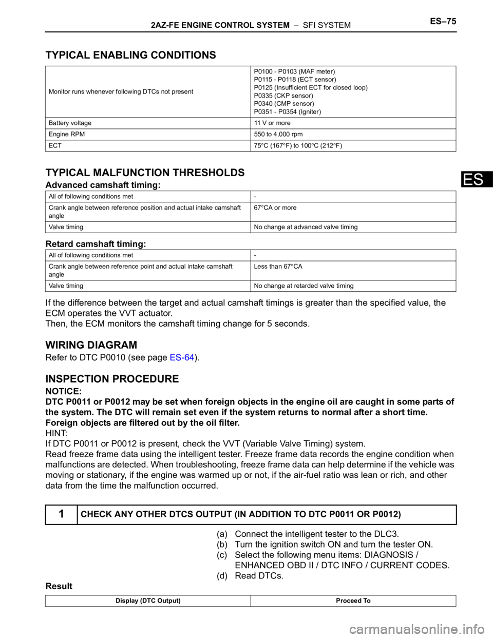
TYPICAL ENABLING CONDITIONS
TYPICAL MALFUNCTION THRESHOLDS
Advanced camshaft timing:
Retard camshaft timing:
If the difference between the target and actual camshaft timings is greater than the specified value, the
ECM operates the VVT actuator.
Then, the ECM monitors the camshaft timing change for 5 seconds.
WIRING DIAGRAM
Refer to DTC P0010 (see page ES-64).
INSPECTION PROCEDURE
NOTICE:
DTC P0011 or P0012 may be set when foreign objects in the engine oil are caught in some parts of
the system. The DTC will remain set even if the system returns to normal after a short time.
Foreign objects are filtered out by the oil filter.
HINT:
If DTC P0011 or P0012 is present, check the VVT (Variable Valve Timing) system.
Read freeze frame data using the intelligent tester. Freeze frame data records the engine condition when
malfunctions are detected. When troubleshooting, freeze frame data can help determine if the vehicle was
moving or stationary, if the engine was warmed up or not, if the air-fuel ratio was lean or rich, and other
data from the time the malfunction occurred.
(a) Connect the intelligent tester to the DLC3.
(b) Turn the ignition switch ON and turn the tester ON.
(c) Select the following menu items: DIAGNOSIS /
ENHANCED OBD II / DTC INFO / CURRENT CODES.
(d) Read DTCs.
Result
Monitor runs whenever following DTCs not presentP0100 - P0103 (MAF meter)
P0115 - P0118 (ECT sensor)
P0125 (Insufficient ECT for closed loop)
P0335 (CKP sensor)
P0340 (CMP sensor)
P0351 - P0354 (Igniter)
Battery voltage 11 V or more
Engine RPM 550 to 4,000 rpm
ECT 75
C (167F) to 100C (212F)
All of following conditions met -
Crank angle between reference position and actual intake camshaft
angle67
CA or more
Valve timing No change at advanced valve timing
All of following conditions met -
Crank angle between reference point and actual intake camshaft
angleLess than 67
CA
Valve timing No change at retarded valve timing
1CHECK ANY OTHER DTCS OUTPUT (IN ADDITION TO DTC P0011 OR P0012)
Display (DTC Output) Proceed To
Page 1964 of 2000
ES–762AZ-FE ENGINE CONTROL SYSTEM – SFI SYSTEM
ES
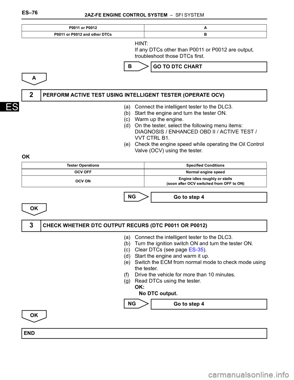
HINT:
If any DTCs other than P0011 or P0012 are output,
troubleshoot those DTCs first.
B
A
(a) Connect the intelligent tester to the DLC3.
(b) Start the engine and turn the tester ON.
(c) Warm up the engine.
(d) On the tester, select the following menu items:
DIAGNOSIS / ENHANCED OBD II / ACTIVE TEST /
VVT CTRL B1.
(e) Check the engine speed while operating the Oil Control
Valve (OCV) using the tester.
OK
NG
OK
(a) Connect the intelligent tester to the DLC3.
(b) Turn the ignition switch ON and turn the tester ON.
(c) Clear DTCs (see page ES-35).
(d) Start the engine and warm it up.
(e) Switch the ECM from normal mode to check mode using
the tester.
(f) Drive the vehicle for more than 10 minutes.
(g) Read DTCs using the tester.
OK:
No DTC output.
NG
OK
P0011 or P0012 A
P0011 or P0012 and other DTCs B
GO TO DTC CHART
2PERFORM ACTIVE TEST USING INTELLIGENT TESTER (OPERATE OCV)
Tester Operations Specified Conditions
OCV OFF Normal engine speed
OCV ONEngine idles roughly or stalls
(soon after OCV switched from OFF to ON)
Go to step 4
3CHECK WHETHER DTC OUTPUT RECURS (DTC P0011 OR P0012)
Go to step 4
END
Page 1965 of 2000
2AZ-FE ENGINE CONTROL SYSTEM – SFI SYSTEMES–77
ES
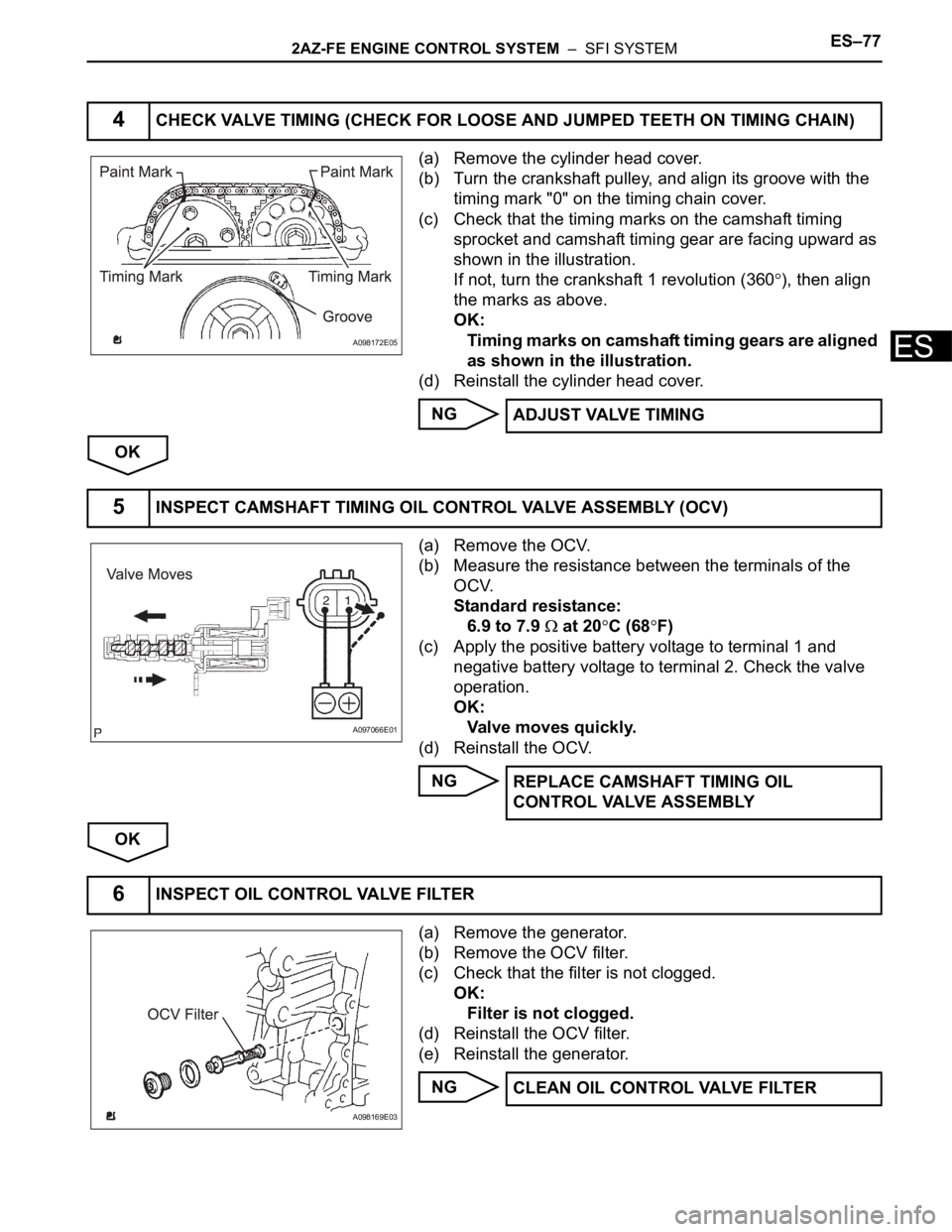
(a) Remove the cylinder head cover.
(b) Turn the crankshaft pulley, and align its groove with the
timing mark "0" on the timing chain cover.
(c) Check that the timing marks on the camshaft timing
sprocket and camshaft timing gear are facing upward as
shown in the illustration.
If not, turn the crankshaft 1 revolution (360
), then align
the marks as above.
OK:
Timing marks on camshaft timing gears are aligned
as shown in the illustration.
(d) Reinstall the cylinder head cover.
NG
OK
(a) Remove the OCV.
(b) Measure the resistance between the terminals of the
OCV.
Standard resistance:
6.9 to 7.9
at 20C (68F)
(c) Apply the positive battery voltage to terminal 1 and
negative battery voltage to terminal 2. Check the valve
operation.
OK:
Valve moves quickly.
(d) Reinstall the OCV.
NG
OK
(a) Remove the generator.
(b) Remove the OCV filter.
(c) Check that the filter is not clogged.
OK:
Filter is not clogged.
(d) Reinstall the OCV filter.
(e) Reinstall the generator.
NG
4CHECK VALVE TIMING (CHECK FOR LOOSE AND JUMPED TEETH ON TIMING CHAIN)
A098172E05
ADJUST VALVE TIMING
5INSPECT CAMSHAFT TIMING OIL CONTROL VALVE ASSEMBLY (OCV)
A097066E01
REPLACE CAMSHAFT TIMING OIL
CONTROL VALVE ASSEMBLY
6INSPECT OIL CONTROL VALVE FILTER
A098169E03
CLEAN OIL CONTROL VALVE FILTER
Page 1966 of 2000
ES–782AZ-FE ENGINE CONTROL SYSTEM – SFI SYSTEM
ES
OK
NEXT
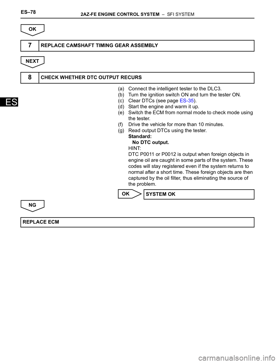
(a) Connect the intelligent tester to the DLC3.
(b) Turn the ignition switch ON and turn the tester ON.
(c) Clear DTCs (see page ES-35).
(d) Start the engine and warm it up.
(e) Switch the ECM from normal mode to check mode using
the tester.
(f) Drive the vehicle for more than 10 minutes.
(g) Read output DTCs using the tester.
Standard:
No DTC output.
HINT:
DTC P0011 or P0012 is output when foreign objects in
engine oil are caught in some parts of the system. These
codes will stay registered even if the system returns to
normal after a short time. These foreign objects are then
captured by the oil filter, thus eliminating the source of
the problem.
OK
NG
7REPLACE CAMSHAFT TIMING GEAR ASSEMBLY
8CHECK WHETHER DTC OUTPUT RECURS
SYSTEM OK
REPLACE ECM
Page 1967 of 2000

2AZ-FE ENGINE CONTROL SYSTEM – SFI SYSTEMES–79
ES
DESCRIPTION
In the VVT (Variable Valve Timing) system, the appropriate intake valve open and close timing is
controlled by the ECM. The ECM performs intake valve control by performing the following: 1) controlling
the camshaft and camshaft timing oil control valve, and operating the camshaft timing gear; and 2)
changing the relative positions of the gaps between the camshaft and crankshaft.
MONITOR DESCRIPTION
The ECM optimizes the valve timing by using the VVT (Variable Valve Timing) system to control the intake
camshaft. The VVT system includes the ECM, the Oil Control Valve (OCV) and the VVT controller.
The ECM sends a target duty-cycle control signal to the OCV. This control signal regulates the oil
pressure supplied to the VVT controller. The VVT controller can advance or retard the intake camshaft.
The ECM calibrates the intake valve timing by setting the intake camshaft to the most retarded angle while
the engine is idling. The ECM closes the OCV to retard the cam. The ECM stores this value as the VVT
learning value. When the difference between the target and actual intake valve timings is 5
CA
(Crankshaft Angle) or less, the ECM stores it.
If the VVT learning value matches the following conditions, the ECM determines the existence of a
malfunction in the VVT system, and sets the DTC.
• VVT learning value: Less than 25
CA, or more than 51CA.
• Above condition continues for 18 seconds or more.
This DTC indicates that the angle between the intake camshaft and the crankshaft is incorrect due to
factors such as the timing chain having jumped a tooth.
This monitor begins to run after the engine has idled for 5 minutes.
MONITOR STRATEGY
TYPICAL ENABLING CONDITIONS
TYPICAL MALFUNCTION THRESHOLDS
DTC P0016Crankshaft Position - Camshaft Position Corre-
lation (Bank 1 Sensor A)
DTC No. DTC Detection Conditions Trouble Areas
P0016Deviation in crankshaft and camshaft position sensor signals
(2 trip detection logic)• Mechanical system (Timing chain has jumped tooth or
chain stretched)
•ECM
Related DTCs P0016: Camshaft timing misalignment at idling
Required Sensors/Components VVT actuator
Required Sensors/Components Camshaft position sensor, Crankshaft position sensor
Frequency of Operation Once per driving cycle
Duration Within 1 minute
MIL Operation 2 driving cycles
Sequence of Operation None
Monitor runs whenever following DTCs not presentP0011 (VVT system 1 - advance)
P0012 (VVT system 1 - retarded)
P0115 - P0118 (ECT sensor)
Engine RPM 550 to 1,000 rpm
One of following conditions met -
VVT learning value when camshaft maximum retarded Less than 27.8
CA
VVT learning value when camshaft maximum retarded More than 48
CA
Page 1968 of 2000
ES–802AZ-FE ENGINE CONTROL SYSTEM – SFI SYSTEM
ES
WIRING DIAGRAM
Refer to DTC P0335 (see page ES-172).
INSPECTION PROCEDURE
HINT:
Read freeze frame data using the intelligent tester. Freeze frame data records the engine condition when
malfunctions are detected. When troubleshooting, freeze frame data can help determine if the vehicle was
moving or stationary, if the engine was warmed up or not, if the air-fuel ratio was lean or rich, and other
data from the time the malfunction occurred.
NG
OK
NEXT
NEXT
NOTICE:
After replacing the ECM or adjusting intake valve timing,
confirm that the DTC output does not recur.
(a) Connect the intelligent tester to the DLC3.
(b) Turn the ignition switch ON.
(c) Turn the tester ON.
(d) Clear DTCs (see page ES-35).
(e) Switch the ECM from normal mode to check mode using
the tester (see page ES-38).
(f) Start the engine and warm it up.
(g) Allow the engine to idle for 1 minute or more, and then
drive the vehicle for 1 minute or more.
(h) Confirm that no DTC is set, using the tester.
OK:
No DTC output
NEXT
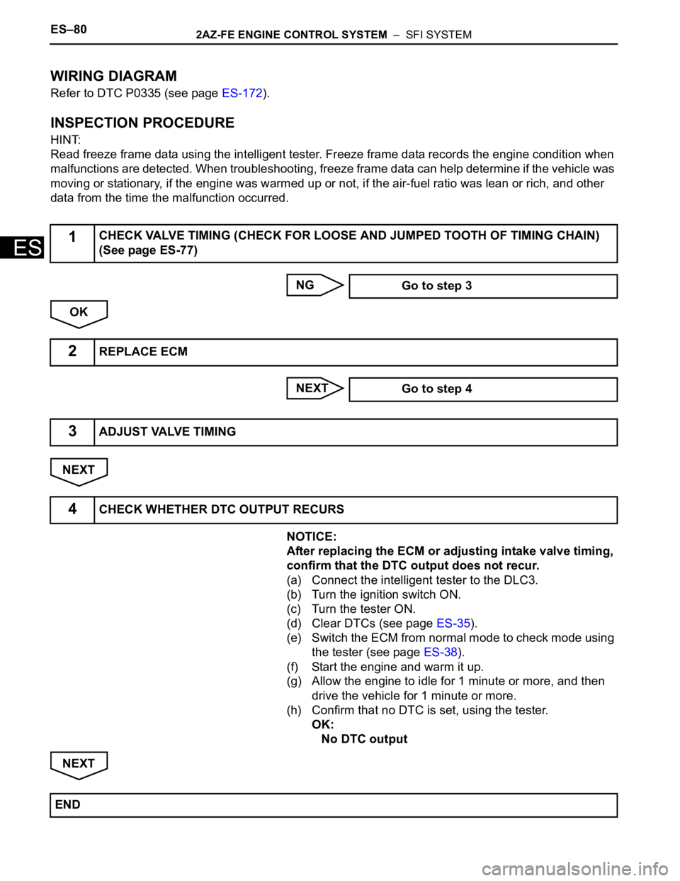
1CHECK VALVE TIMING (CHECK FOR LOOSE AND JUMPED TOOTH OF TIMING CHAIN)
(See page ES-77)
Go to step 3
2REPLACE ECM
Go to step 4
3ADJUST VALVE TIMING
4CHECK WHETHER DTC OUTPUT RECURS
END
Page 1969 of 2000
2AZ-FE ENGINE CONTROL SYSTEM – SFI SYSTEMES–81
ES
HINT:
• Although the DTC titles say oxygen sensor, these DTCs relate to the Air-Fuel Ratio (A/F) sensor.
• Sensor 1 refers to the sensor mounted in front of the Three-Way Catalytic Converter (TWC) and
located near the engine assembly.
DESCRIPTION
Refer to DTC P2195 (see page ES-292).
HINT:
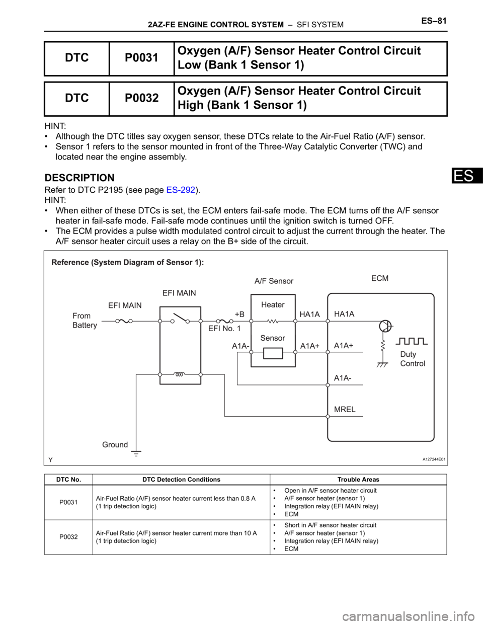
• When either of these DTCs is set, the ECM enters fail-safe mode. The ECM turns off the A/F sensor
heater in fail-safe mode. Fail-safe mode continues until the ignition switch is turned OFF.
• The ECM provides a pulse width modulated control circuit to adjust the current through the heater. The
A/F sensor heater circuit uses a relay on the B+ side of the circuit.
DTC P0031Oxygen (A/F) Sensor Heater Control Circuit
Low (Bank 1 Sensor 1)
DTC P0032Oxygen (A/F) Sensor Heater Control Circuit
High (Bank 1 Sensor 1)
DTC No. DTC Detection Conditions Trouble Areas
P0031Air-Fuel Ratio (A/F) sensor heater current less than 0.8 A
(1 trip detection logic)• Open in A/F sensor heater circuit
• A/F sensor heater (sensor 1)
• Integration relay (EFI MAIN relay)
•ECM
P0032Air-Fuel Ratio (A/F) sensor heater current more than 10 A
(1 trip detection logic)• Short in A/F sensor heater circuit
• A/F sensor heater (sensor 1)
• Integration relay (EFI MAIN relay)
•ECM
A127244E01
Page 1970 of 2000

ES–822AZ-FE ENGINE CONTROL SYSTEM – SFI SYSTEM
ES
MONITOR DESCRIPTION
The ECM uses information from the Air-Fuel Ratio (A/F) sensor to regulate the air-fuel ratio and keep it
close to the stoichiometric level. This maximizes the ability of the Three-Way Catalytic Converter (TWC) to
purify the exhaust gases.
The A/F sensor detects oxygen levels in the exhaust gas and transmits the information to the ECM. The
inner surface of the sensor element is exposed to the outside air. The outer surface of the sensor element
is exposed to the exhaust gas. The sensor element is made of platinum coated zirconia and includes an
integrated heating element.
The zirconia element generates a small voltage when there is a large difference in the oxygen
concentrations between the exhaust gas and outside air. The platinum coating amplifies this voltage
generation.
The A/F sensor is more efficient when heated. When the exhaust gas temperature is low, the sensor
cannot generate useful voltage signals without supplementary heating. The ECM regulates the
supplementary heating using a duty-cycle approach to adjust the average current in the sensor heater
element. If the heater current is outside the normal range, the signal transmitted by the A/F sensor
becomes inaccurate, as a result, the ECM is unable to regulate air-fuel ratio properly.
When the current in the A/F sensor heater is outside the normal operating range, the ECM interprets this
as a malfunction in the sensor heater and sets a DTC.
Example:
The ECM sets DTC P0032 when the current in the A/F sensor heater is more than 10 A. Conversely,
when the heater current is less than 0.8 A, DTC P0031 is set.
MONITOR STRATEGY
TYPICAL ENABLING CONDITIONS
All:
P0031:
P0032:
TYPICAL MALFUNCTION THRESHOLDS
P0031:
P0032:
Related DTCsP0031: A/F sensor heater open/short (Low electrical current)
P0032: A/F sensor heater open/short (High electrical current)
Required Sensors/Components (Main) A/F sensor heater
Required Sensors/Components (Related) -
Frequency of Operation Continuous
Duration 10 seconds
MIL Operation Immediate
Sequence of Operation None
Monitor runs whenever following DTCs not present None
Battery voltage 10.5 V or more
A/F sensor heater duty-cycle ratio 50 % or more
Time after engine start 10 seconds or more
Time after engine start 10 seconds or more
A/F sensor heater current Less than 0.8 A
A/F sensor heater current More than 10 A