TOYOTA RAV4 2006 Service Repair Manual
Manufacturer: TOYOTA, Model Year: 2006, Model line: RAV4, Model: TOYOTA RAV4 2006Pages: 2000, PDF Size: 45.84 MB
Page 1941 of 2000

2AZ-FE ENGINE CONTROL SYSTEM – SFI SYSTEMES–53
ES
SPD TESTCheck mode result for vehicle
speed sensor:
COMPL or INCMPL--
MISFIRE TESTCheck mode result for misfire
monitor:
COMPL or INCMPL--
OXS1 TESTCheck mode result for HO2
sensor:
COMPL or INCMPL--
A/F SSR TEST B1Check mode result for air-fuel
ratio sensor:
COMPL or INCMPL--
MIL MIL status:
ON or OFFON: MIL ON -
MIL ON RUN DISTMIL ON run distance:
Min.: 0 km, Max.: 65,535 kmDistance after DTC detected -
MIL ON RUN TIMERunning time from MIL ON:
Min.: 0 minutes,
Max.: 65,535 minutesEquivalent to running time after
MIL ON-
ENG RUN TIMEEngine run time:
Min.: 0 seconds,
Max.: 65,535 secondsTime after engine start -
TIME DTC CLEARTime after DTC cleared:
Min.: 0 minutes,
Max.: 65,535 minutesEquivalent to time after DTCs
erased-
DIST DTC CLEARDistance after DTC cleared:
Min.: 0 km, Max.: 65,535 kmEquivalent to drive distance
after DTCs erased-
WU CYC DTC CLEARWarm-up cycle after DTC cleared:
Min.: 0, Max.: 255-Number of warm-up cycles after
DTC cleared
OBD CERT OBD requirement OBD2 -
#CARB CODES Emission related DTCs - Number of emission related DTCs
COMP MONComprehensive component
monitor:
N O T AV L o r AVA I L--
FUEL MONFuel system monitor:
N O T AV L o r AVA I L--
MISFIRE MONMisfire monitor:
N O T AV L o r AVA I L--
O2S (A/FS) HTRO2S (A/FS ) heater monitor:
N O T AV L o r AVA I L--
O2S (A/FS) HTRO2S (A/FS ) heater monitor:
COMPL or INCMPL--
O2S (A/FS) MONO2S (A/FS ) monitor:
N O T AV L o r AVA I L--
O2S (A/FS) MONO2S (A/FS ) monitor:
COMPL or INCMPL--
EVAP MONEVAP monitor:
N O T AV L o r AVA I L--
EVAP MONEVAP monitor:
COMPL or INCMPL--
CAT MONCatalyst monitor:
N O T AV L o r AVA I L--
CAT MONCatalyst monitor:
COMPL or INCMPL--
CCM ENAComprehensive component
monitor:
UNABLE or ENABLE-- Intelligent Tester Display Measurement: Range (Display) Normal Condition*1 Diagnostic Note
Page 1942 of 2000

ES–542AZ-FE ENGINE CONTROL SYSTEM – SFI SYSTEM
ES
HINT:
• *1: If no idling conditions are specified, the transmission
gear selector lever should be in the N or P position, and
the A/C switch and all accessory switches should be OFF.
• *2: DATA LIST values are only displayed when performing
the following ACTIVE TEST: VVT B1. For other ACTIVE
TESTs, the DATA LIST value will be 0.
2. ACTIVE TEST
HINT:
Performing an ACTIVE TEST enables components
including the relays, VSV (Vacuum Switching Valve) and
actuators, to be operated without removing any parts.
The ACTIVE TEST can be performed with the intelligent
tester. Performing the ACTIVE TEST as the first step of
troubleshooting is one method of shortening diagnostic
time.
DATA LIST can be displayed during ACTIVE TEST.
(a) Connect the intelligent tester to the DLC3.
(b) Turn the ignition switch ON.
CCM CMPLComprehensive component
monitor:
COMPL or INCMPL--
FUEL ENAFuel system monitor:
UNABLE or ENABLE--
FUEL CMPLFuel system monitor:
COMPL or INCMPL--
MISFIRE ENAMisfire monitor:
UNABLE or ENABLE--
MISFIRE CMPLMisfire monitor:
COMPL or INCMPL--
HTR ENAO2S (A/FS) heater monitor:
UNABLE or ENABLE--
HTR CMPLO2S (A/FS) heater monitor:
COMPL or INCMPL--
O2S (A/FS) ENAO2S (A/FS) monitor:
UNABLE or ENABLE--
O2S (A/FS) CMPLO2S (A/FS) monitor:
COMPL or INCMPL--
EVAP ENAEVAP monitor:
UNABLE or ENABLE--
EVAP CMPLEVAP monitor:
COMPL or INCMPL--
CAT ENACatalyst monitor:
UNABLE or ENABLE--
CAT CMPLCatalyst monitor:
COMPL or INCMPL--
MODEL CODE Identifying model code ACA3# -
ENGINE TYPE Identifying engine type 2AZFE -
CYLINDER NUMBERIdentifying cylinder number:
Min.: 0, Max.: 2554-
TRANSMISSION Identifying transmission type 4AT -
DESTINATION Identifying destination A (America) -
MODEL YEARIdentifying model year:
Min.: 1900, Max.: 2155200# -
SYSTEM Identifying engine system GASLIN (gasoline engine) -Intelligent Tester Display Measurement: Range (Display) Normal Condition*1 Diagnostic Note
Page 1943 of 2000

2AZ-FE ENGINE CONTROL SYSTEM – SFI SYSTEMES–55
ES
(c) Turn the tester ON.
(d) Select the following menu items: DIAGNOSIS /
ENHANCED OBD II / ACTIVE TEST.
(e) Perform the ACTIVE TEST by referring to the table
below.
ECM:
Intelligent Tester Displays Test Details Control Ranges Diagnostic Notes
INJ VOL Change injection volume Between -12.5 and 24.8 %• All injectors tested at same
time
• Perform test at less than
3,000 rpm
• Injection volume can be
changed in 0.1 % graduations
within control range
A/F CONTROL Change injection volumeDecrease by 12.5 % or increase
by 24.8 %• Perform test at less than
3,000 rpm
• A/F CONTROL enables
checking and graphing of A/F
(Air-Fuel Ratio) sensor and
Heated Oxygen (HO2) sensor
voltage outputs
• To conduct test, select
following menu items:
ACTIVE TEST / A/F
CONTROL / USER DATA /
AFS B1S1 and O2S B1S2;
then press YES and ENTER
followed by F4.
EVAP VSV (ALONE) Activate purge VSV control ON/OFF -
VVT B1 Control VVT (bank 1)-128 to 127 %
This value added to present OCV
control duty
100 %: Maximum advance
-100 %: Maximum retardEngine stall or rough idle when
VVT actuator operated by 100 %.
Test possible while vehicle
stopped and engine idling
VVT CTRL B1Turn on and off OCV
(Oil Control Valve)ON/OFF• Engine stalls or idles roughly
when OCV turned ON
• Normal engine running or
idling when OCV OFF
• Test possible while vehicle
stopped and engine idling
FUEL PUMP / SPDActivate fuel pump (C/OPN
Relay)ON/OFFTest possible when engine
stopped
TC/TE1Turn on and off TC and TE1
connectionON/OFF• ON: TC and TE1 connected
• OFF: TC and TE1
disconnected
FC IDL PROHBT Prohibit idling fuel cut control ON/OFF -
COOLING FAN Control electric cooling fan ON/OFF -
ETCS OPEN SLOW Throttle actuator ON: Throttle valve opens slowly Test possible when following
conditions met:
• Engine stopped
• Shift position in P
• Fully depressing accelerator
pedal (APP: 59
or more) ETCS CLOSE SLOW Throttle actuator ON: Throttle valve closes slowly
ETCS OPEN FAST Throttle actuator ON: Throttle valve opens fast
ETCS CLOSE FAST Throttle actuator ON: Throttle valve closes fast
FUEL CUT #1 Cylinder #1 injector fuel cut ON/OFF
Test possible during vehicle
stopping and engine idling
ON: All cylinder injector fuel cut
and ignition stop FUEL CUT #2 Cylinder #2 injector fuel cut ON/OFF
FUEL CUT #3 Cylinder #3 injector fuel cut ON/OFF
FUEL CUT #4 Cylinder #4 injector fuel cut ON/OFF
FUEL CUT ALL All cylinder injector fuel cut ON/OFF ON: All cylinder injector fuel cut
VACUUM PUMP Leak detection pump ON/OFF -
VENT VALVE Vent valve ON/OFF -
Page 1944 of 2000
ES–562AZ-FE ENGINE CONTROL SYSTEM – SFI SYSTEM
ES
HINT:
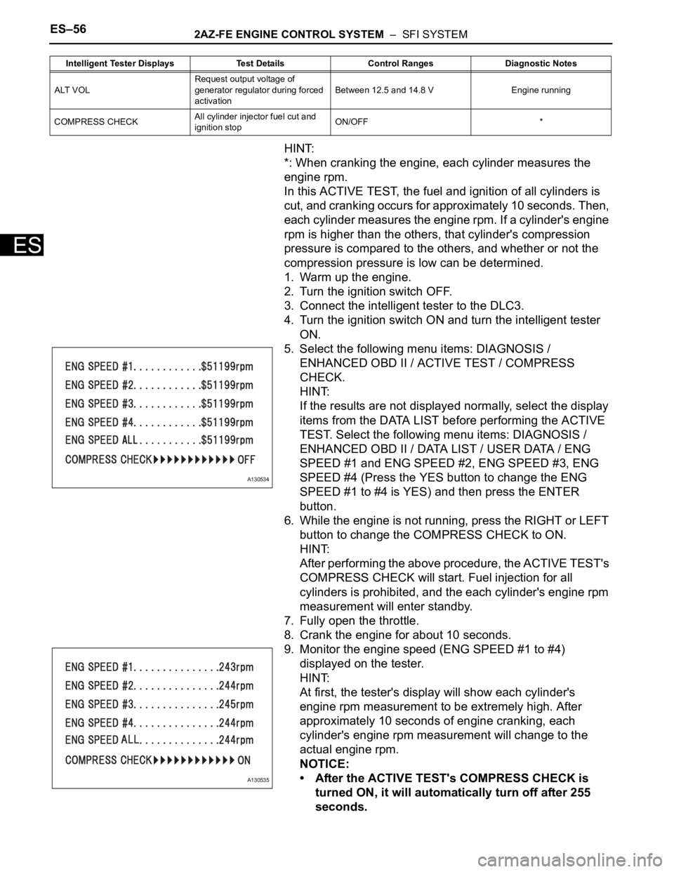
*: When cranking the engine, each cylinder measures the
engine rpm.
In this ACTIVE TEST, the fuel and ignition of all cylinders is
cut, and cranking occurs for approximately 10 seconds. Then,
each cylinder measures the engine rpm. If a cylinder's engine
rpm is higher than the others, that cylinder's compression
pressure is compared to the others, and whether or not the
compression pressure is low can be determined.
1. Warm up the engine.
2. Turn the ignition switch OFF.
3. Connect the intelligent tester to the DLC3.
4. Turn the ignition switch ON and turn the intelligent tester
ON.
5. Select the following menu items: DIAGNOSIS /
ENHANCED OBD II / ACTIVE TEST / COMPRESS
CHECK.
HINT:
If the results are not displayed normally, select the display
items from the DATA LIST before performing the ACTIVE
TEST. Select the following menu items: DIAGNOSIS /
ENHANCED OBD II / DATA LIST / USER DATA / ENG
SPEED #1 and ENG SPEED #2, ENG SPEED #3, ENG
SPEED #4 (Press the YES button to change the ENG
SPEED #1 to #4 is YES) and then press the ENTER
button.
6. While the engine is not running, press the RIGHT or LEFT
button to change the COMPRESS CHECK to ON.
HINT:
After performing the above procedure, the ACTIVE TEST's
COMPRESS CHECK will start. Fuel injection for all
cylinders is prohibited, and the each cylinder's engine rpm
measurement will enter standby.
7. Fully open the throttle.
8. Crank the engine for about 10 seconds.
9. Monitor the engine speed (ENG SPEED #1 to #4)
displayed on the tester.
HINT:
At first, the tester's display will show each cylinder's
engine rpm measurement to be extremely high. After
approximately 10 seconds of engine cranking, each
cylinder's engine rpm measurement will change to the
actual engine rpm.
NOTICE:
• After the ACTIVE TEST's COMPRESS CHECK is
turned ON, it will automatically turn off after 255
seconds.
ALT VOLRequest output voltage of
generator regulator during forced
activationBetween 12.5 and 14.8 V Engine running
COMPRESS CHECKAll cylinder injector fuel cut and
ignition stopON/OFF * Intelligent Tester Displays Test Details Control Ranges Diagnostic Notes
A130534
A130535
Page 1945 of 2000

2AZ-FE ENGINE CONTROL SYSTEM – SFI SYSTEMES–57
ES
• When the COMPRESS CHECK test is OFF and the
engine is cranked, the engine will start.
• If the COMPRESS CHECK test needs to be
performed after it is turned ON and performed once,
press EXIT to return to the ACTIVE TEST menu
screen. Then perform the COMPRESS CHECK test
again.
• Use a fully-charged battery.
3. SYSTEM CHECK
HINT:
Performing a SYSTEM CHECK enables the system,
which consists of multiple actuators, to be operated
without removing any parts. In addition, it can show
whether or not any DTCs are set, and can detect
potential malfunctions in the system. The SYSTEM
CHECK can be performed with the intelligent tester.
(a) Connect the intelligent tester to the DLC3.
(b) Turn the ignition switch ON.
(c) Turn the tester ON.
(d) Select the following menu items: DIAGNOSIS /
ENHANCED OBD II / SYSTEM CHECK.
(e) Perform the SYSTEM CHECK by referring to the
table below.
ECM:
Intelligent Tester Display Test DetailRecommended Fuel
Te m p e r a t u r eDiagnostic Note
EVAP SYS CHECK
(AUTO OPERATION)Perform 5 steps in order to
operate EVAP key-off monitor
automatically35
C (95F) or less• If no DTCs in PENDING
CODE after performing this
test, system functioning
normally
• Refer to EVAP system
EVAP SYS CHECK
(MANUAL OPERATION)Perform 5 steps in order to
operate EVAP key-off monitor
manually35
C (95F) or less• Used to detect malfunctioning
parts
• Refer to EVAP system
Page 1946 of 2000
ES–582AZ-FE ENGINE CONTROL SYSTEM – SFI SYSTEM
ES
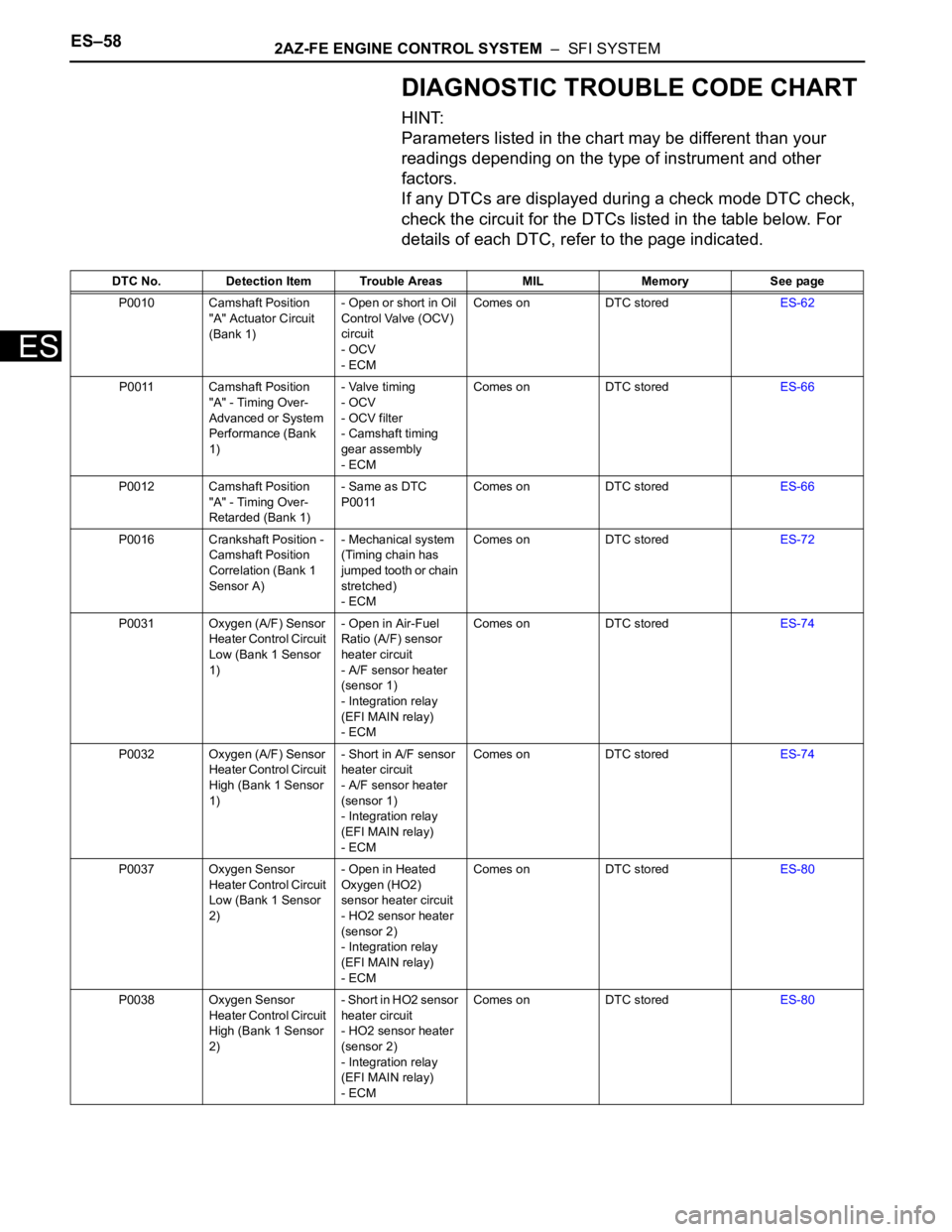
DIAGNOSTIC TROUBLE CODE CHART
HINT:
Parameters listed in the chart may be different than your
readings depending on the type of instrument and other
factors.
If any DTCs are displayed during a check mode DTC check,
check the circuit for the DTCs listed in the table below. For
details of each DTC, refer to the page indicated.
DTC No. Detection Item Trouble Areas MIL Memory See page
P0010 Camshaft Position
"A" Actuator Circuit
(Bank 1)- Open or short in Oil
Control Valve (OCV)
circuit
- OCV
- ECMComes on DTC storedES-62
P0011 Camshaft Position
"A" - Timing Over-
Advanced or System
Performance (Bank
1)- Valve timing
- OCV
- OCV filter
- Camshaft timing
gear assembly
- ECMComes on DTC storedES-66
P0012 Camshaft Position
"A" - Timing Over-
Retarded (Bank 1)- Same as DTC
P0011Comes on DTC storedES-66
P0016 Crankshaft Position -
Camshaft Position
Correlation (Bank 1
Sensor A)- Mechanical system
(Timing chain has
jumped tooth or chain
stretched)
- ECMComes on DTC storedES-72
P0031 Oxygen (A/F) Sensor
Heater Control Circuit
Low (Bank 1 Sensor
1)- Open in Air-Fuel
Ratio (A/F) sensor
heater circuit
- A/F sensor heater
(sensor 1)
- Integration relay
(EFI MAIN relay)
- ECMComes on DTC storedES-74
P0032 Oxygen (A/F) Sensor
Heater Control Circuit
High (Bank 1 Sensor
1)- Short in A/F sensor
heater circuit
- A/F sensor heater
(sensor 1)
- Integration relay
(EFI MAIN relay)
- ECMComes on DTC storedES-74
P0037 Oxygen Sensor
Heater Control Circuit
Low (Bank 1 Sensor
2)- Open in Heated
Oxygen (HO2)
sensor heater circuit
- HO2 sensor heater
(sensor 2)
- Integration relay
(EFI MAIN relay)
- ECMComes on DTC storedES-80
P0038 Oxygen Sensor
Heater Control Circuit
High (Bank 1 Sensor
2)- Short in HO2 sensor
heater circuit
- HO2 sensor heater
(sensor 2)
- Integration relay
(EFI MAIN relay)
- ECMComes on DTC storedES-80
Page 1947 of 2000
2AZ-FE ENGINE CONTROL SYSTEM – SFI SYSTEMES–59
ES
P0100 Mass or Volume Air
Flow Circuit- Open or short in
Mass Air Flow (MAF)
meter circuit
- MAF meter
- ECMComes on DTC storedES-86
P0101 Mass Air Flow Circuit
Range / Performance
Problem- MAF meter
- Air induction system
- PCV hose
connectionsComes on DTC storedES-93
P0102 Mass or Volume Air
Flow Circuit Low
Input- Open or short in
MAF meter circuit
- MAF meter
- ECMComes on DTC storedES-86
P0103 Mass or Volume Air
Flow Circuit High
Input- Open or short in
MAF meter circuit
- MAF meter
- ECMComes on DTC storedES-86
P0110 Intake Air
Temperature Circuit
Malfunction- Open or short in
Intake Air
Temperature (IAT)
sensor circuit
- IAT sensor (built into
MAF meter)
- ECMComes on DTC storedES-96
P0111 Intake Air
Temperature Sensor
Gradient Too High- Mass air flow meter
assemblyComes on DTC storedES-102
P0112 Intake Air
Temperature Circuit
Low Input- Short in IAT sensor
circuit
- IAT sensor (built into
MAF meter)
- ECMComes on DTC storedES-96
P0113 Intake Air
Temperature Circuit
High Input- Open in IAT sensor
circuit
- IAT sensor (built into
MAF meter)
- ECMComes on DTC storedES-96
P0115 Engine Coolant
Temperature Circuit
Malfunction- Open or short in
Engine Coolant
Temperature (ECT)
sensor circuit
- ECT sensor
- ECMComes on DTC storedES-105
P0116 Engine Coolant
Temperature Circuit
Range / Performance
Problem- Thermostat
- ECT sensorComes on DTC storedES-111
P0117 Engine Coolant
Temperature Circuit
Low Input- Short in ECT sensor
circuit
- ECT sensor
- ECMComes on DTC storedES-105
P0118 Engine Coolant
Temperature Circuit
High Input- O p e n i n E C T s e n s o r
circuit
- ECT sensor
- ECMComes on DTC storedES-105
P0120 Throttle Pedal
Position Sensor /
Switch "A" Circuit
Malfunction- Throttle Position
(TP) sensor (built into
throttle body)
- ECMComes on DTC storedES-114
P0121 Throttle / Pedal
Position Sensor /
Switch "A" Circuit
Range / Performance
Problem- TP sensor (built into
throttle body)Comes on DTC storedES-121 DTC No. Detection Item Trouble Areas MIL Memory See page
Page 1948 of 2000
ES–602AZ-FE ENGINE CONTROL SYSTEM – SFI SYSTEM
ES
P0122 Throttle / Pedal
Position Sensor /
Switch "A" Circuit
Low Input- TP sensor (built into
throttle body)
- Short in VTA1 circuit
- Open in VC circuit
- ECMComes on DTC storedES-114
P0123 Throttle / Pedal
Position Sensor /
Switch "A" Circuit
High Input- TP sensor (built into
throttle body)
- Open in VTA1 circuit
- Open in E2 circuit
- Short between VC
and VTA1 circuits
- ECMComes on DTC storedES-114
P0125 Insufficient Coolant
Temperature for
Closed Loop Fuel
Control- Cooling system
- ECT sensor
- ThermostatComes on DTC storedES-123
P0128 Coolant Thermostat
(Coolant
Temperature Below
Thermostat
Regulating
Temperature)- Thermostat
- Cooling system
- ECT sensor
- ECMComes on DTC storedES-126
P0136 Oxygen Sensor
Circuit Malfunction
(Bank 1 Sensor 2)- Open or short in
HO2 sensor (sensor
2) circuit
- HO2 sensor (sensor
2)
- HO2 sensor heater
(sensor 2)
- Air-Fuel Ratio (A/F)
sensor (sensor 1)
- Integration relay
(EFI MAIN relay)
- Gas leakage from
exhaust systemComes on DTC storedES-129
P0137 Oxygen Sensor
Circuit Low Voltage
(Bank 1 Sensor 2)- Open in HO2 sensor
(sensor 2) circuit
- HO2 sensor (sensor
2)
- HO2 sensor heater
(sensor 2)
- Integration relay
(EFI MAIN relay)
- Gas leakage from
exhaust systemComes on DTC storedES-129
P0138 Oxygen Sensor
Circuit High Voltage
(Bank 1 Sensor 2)- Short in HO2 sensor
(sensor 2) circuit
- HO2 sensor (sensor
2)
- ECM internal circuit
malfunctionComes on DTC storedES-129
P0141 Oxygen Sensor
Heater Circuit
Malfunction (Bank 1
Sensor 2)- Open or short in
HO2 sensor heater
circuit
- HO2 sensor heater
(sensor 2)
- Integration relay
(EFI MAIN relay)
- ECMComes on DTC storedES-80 DTC No. Detection Item Trouble Areas MIL Memory See page
Page 1949 of 2000

2AZ-FE ENGINE CONTROL SYSTEM – SFI SYSTEMES–61
ES
P0171 System Too Lean
(Bank 1)- Air induction system
- Injector blockage
- MAF meter
- ECT sensor
- Fuel pressure
- Gas leakage from
exhaust system
- Open or short in A/F
sensor (sensor 1)
circuit
- A/F sensor (sensor
1)
- A/F sensor heater
(sensor 1)
- Integration relay
(EFI MAIN relay)
- A/F sensor heater
and EFI MAIN relay
circuits
- PCV hose
connections
- PCV valve and hose
- ECMComes on DTC storedES-147
P0172 System Too Rich
(Bank 1)- Injector leakage or
blockage
- MAF meter
- ECT sensor
- Ignition system
- Fuel pressure
- Gas leakage from
exhaust system
- Open or short in A/F
sensor (sensor 1)
circuit
- A/F sensor (sensor
1)
- A/F sensor heater
(sensor 1)
- Integration relay
(EFI MAIN relay)
- A/F sensor heater
and EFI MAIN relay
circuits
- ECMComes on DTC storedES-147
P0220 Throttle / Pedal
Position Sensor /
Switch "B" Circuit- TP sensor (built into
throttle body)
- ECMComes on DTC storedES-114
P0222 Throttle / Pedal
Position Sensor /
Switch "B" Circuit
Low Input- TP sensor (built into
throttle body)
- Short in VTA2 circuit
- Open in VC circuit
- ECMComes on DTC storedES-114
P0223 Throttle / Pedal
Position Sensor /
Switch "B" Circuit
High Input- TP sensor (built into
throttle body)
- Open in VTA2 circuit
- Open in E2 circuit
- Short between VC
and VTA2 circuits
- ECMComes on DTC storedES-114 DTC No. Detection Item Trouble Areas MIL Memory See page
Page 1950 of 2000
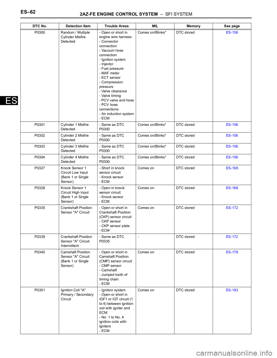
ES–622AZ-FE ENGINE CONTROL SYSTEM – SFI SYSTEM
ES
P0300 Random / Multiple
Cylinder Misfire
Detected- Open or short in
engine wire harness
- Connector
connection
- Vacuum hose
connection
- Ignition system
- Injector
- Fuel pressure
- MAF meter
- ECT sensor
- Compression
pressure
- Valve clearance
- Valve timing
- PCV valve and hose
- PCV hose
connections
- Air induction system
- ECMComes on/Blinks* DTC storedES-156
P0301 Cylinder 1 Misfire
Detected- Same as DTC
P0300Comes on/Blinks* DTC storedES-156
P0302 Cylinder 2 Misfire
Detected- Same as DTC
P0300Comes on/Blinks* DTC storedES-156
P0303 Cylinder 3 Misfire
Detected- Same as DTC
P0300Comes on/Blinks* DTC storedES-156
P0304 Cylinder 4 Misfire
Detected- Same as DTC
P0300Comes on/Blinks* DTC storedES-156
P0327 Knock Sensor 1
Circuit Low Input
(Bank 1 or Single
Sensor)- Short in knock
sensor circuit
- Knock sensor
- ECMComes on DTC storedES-168
P0328 Knock Sensor 1
Circuit High Input
(Bank 1 or Single
Sensor)- Open in knock
sensor circuit
- Knock sensor
- ECMComes on DTC storedES-168
P0335 Crankshaft Position
Sensor "A" Circuit- Open or short in
Crankshaft Position
(CKP) sensor circuit
- CKP sensor
- CKP sensor plate
- ECMComes on DTC storedES-172
P0339 Crankshaft Position
Sensor "A" Circuit
Intermittent- Same as DTC
P0335- DTC storedES-172
P0340 Camshaft Position
Sensor "A" Circuit
(Bank 1 or Single
Sensor)- Open or short in
Camshaft Position
(CMP) sensor circuit
- CMP sensor
- Camshaft
- Jumped tooth of
timing chain
- ECMComes on DTC storedES-178
P0351 Ignition Coil "A"
Primary / Secondary
Circuit- Ignition system
- Open or short in
IGF1 or IGT circuit (1
to 4) between ignition
coil with igniter and
ECM
- No. 1 to No. 4
ignition coils with
igniters
- ECMComes on DTC storedES-183 DTC No. Detection Item Trouble Areas MIL Memory See page