TOYOTA RAV4 2006 Service Repair Manual
Manufacturer: TOYOTA, Model Year: 2006, Model line: RAV4, Model: TOYOTA RAV4 2006Pages: 2000, PDF Size: 45.84 MB
Page 1951 of 2000
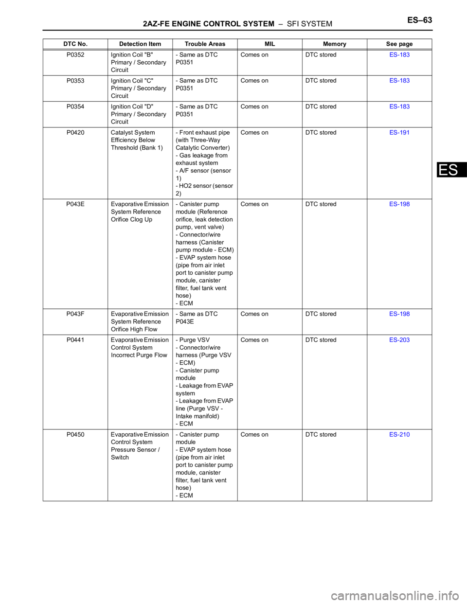
2AZ-FE ENGINE CONTROL SYSTEM – SFI SYSTEMES–63
ES
P0352 Ignition Coil "B"
Primary / Secondary
Circuit- Same as DTC
P0351Comes on DTC storedES-183
P0353 Ignition Coil "C"
Primary / Secondary
Circuit- Same as DTC
P0351Comes on DTC storedES-183
P0354 Ignition Coil "D"
Primary / Secondary
Circuit- Same as DTC
P0351Comes on DTC storedES-183
P0420 Catalyst System
Efficiency Below
Threshold (Bank 1)- Front exhaust pipe
(with Three-Way
Catalytic Converter)
- Gas leakage from
exhaust system
- A/F sensor (sensor
1)
- HO2 sensor (sensor
2)Comes on DTC storedES-191
P043E Evaporative Emission
System Reference
Orifice Clog Up- Canister pump
module (Reference
orifice, leak detection
pump, vent valve)
- Connector/wire
harness (Canister
pump module - ECM)
- EVAP system hose
(pipe from air inlet
port to canister pump
module, canister
filter, fuel tank vent
hose)
- ECMComes on DTC storedES-198
P043F Evaporative Emission
System Reference
Orifice High Flow- Same as DTC
P043EComes on DTC storedES-198
P0441 Evaporative Emission
Control System
Incorrect Purge Flow- Purge VSV
- Connector/wire
harness (Purge VSV
- ECM)
- Canister pump
module
- Leakage from EVAP
system
- Leakage from EVAP
line (Purge VSV -
Intake manifold)
- ECMComes on DTC storedES-203
P0450 Evaporative Emission
Control System
Pressure Sensor /
Switch- Canister pump
module
- EVAP system hose
(pipe from air inlet
port to canister pump
module, canister
filter, fuel tank vent
hose)
- ECMComes on DTC storedES-210 DTC No. Detection Item Trouble Areas MIL Memory See page
Page 1952 of 2000
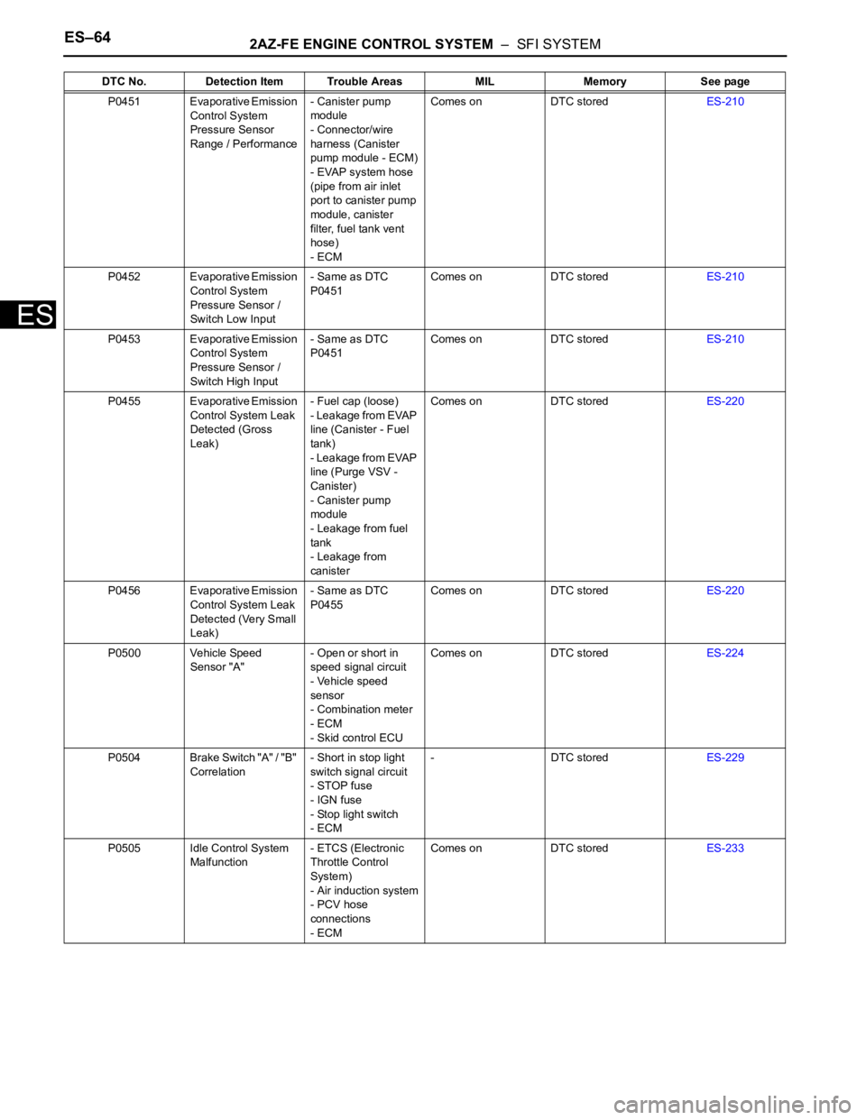
ES–642AZ-FE ENGINE CONTROL SYSTEM – SFI SYSTEM
ES
P0451 Evaporative Emission
Control System
Pressure Sensor
Range / Performance- Canister pump
module
- Connector/wire
harness (Canister
pump module - ECM)
- EVAP system hose
(pipe from air inlet
port to canister pump
module, canister
filter, fuel tank vent
hose)
- ECMComes on DTC storedES-210
P0452 Evaporative Emission
Control System
Pressure Sensor /
Switch Low Input- Same as DTC
P0451Comes on DTC storedES-210
P0453 Evaporative Emission
Control System
Pressure Sensor /
Switch High Input- Same as DTC
P0451Comes on DTC storedES-210
P0455 Evaporative Emission
Control System Leak
Detected (Gross
Leak)- Fuel cap (loose)
- Leakage from EVAP
line (Canister - Fuel
tank)
- Leakage from EVAP
line (Purge VSV -
Canister)
- Canister pump
module
- Leakage from fuel
tank
- Leakage from
canisterComes on DTC storedES-220
P0456 Evaporative Emission
Control System Leak
Detected (Very Small
Leak)- Same as DTC
P0455Comes on DTC storedES-220
P0500 Vehicle Speed
Sensor "A"- Open or short in
speed signal circuit
- Vehicle speed
sensor
- Combination meter
- ECM
- Skid control ECUComes on DTC storedES-224
P0504 Brake Switch "A" / "B"
Correlation- Short in stop light
switch signal circuit
- STOP fuse
- IGN fuse
- Stop light switch
- ECM- DTC storedES-229
P0505 Idle Control System
Malfunction- ETCS (Electronic
Throttle Control
System)
- Air induction system
- PCV hose
connections
- ECMComes on DTC storedES-233 DTC No. Detection Item Trouble Areas MIL Memory See page
Page 1953 of 2000
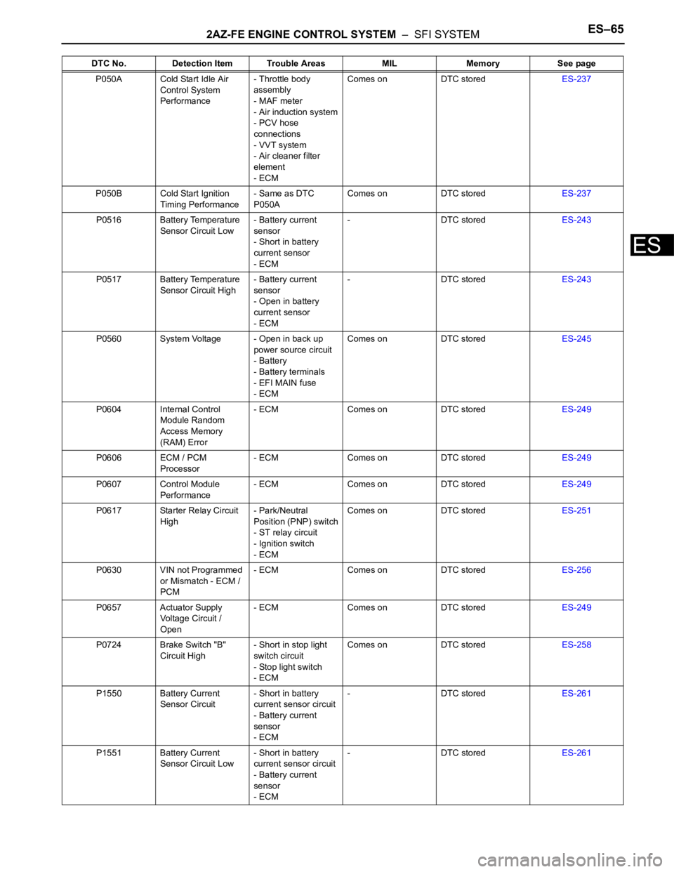
2AZ-FE ENGINE CONTROL SYSTEM – SFI SYSTEMES–65
ES
P050A Cold Start Idle Air
Control System
Performance- Throttle body
assembly
- MAF meter
- Air induction system
- PCV hose
connections
- VVT system
- Air cleaner filter
element
- ECMComes on DTC storedES-237
P050B Cold Start Ignition
Timing Performance- Same as DTC
P050AComes on DTC storedES-237
P0516 Battery Temperature
Sensor Circuit Low- Battery current
sensor
- Short in battery
current sensor
- ECM- DTC storedES-243
P0517 Battery Temperature
Sensor Circuit High- Battery current
sensor
- Open in battery
current sensor
- ECM- DTC storedES-243
P0560 System Voltage - Open in back up
power source circuit
- Battery
- Battery terminals
- EFI MAIN fuse
- ECMComes on DTC storedES-245
P0604 Internal Control
Module Random
Access Memory
(RAM) Error- ECM Comes on DTC storedES-249
P0606 ECM / PCM
Processor- ECM Comes on DTC storedES-249
P0607 Control Module
Performance- ECM Comes on DTC storedES-249
P0617 Starter Relay Circuit
High- Park/Neutral
Position (PNP) switch
- ST relay circuit
- Ignition switch
- ECMComes on DTC storedES-251
P0630 VIN not Programmed
or Mismatch - ECM /
PCM- ECM Comes on DTC storedES-256
P0657 Actuator Supply
Voltage Circuit /
Open- ECM Comes on DTC storedES-249
P0724 Brake Switch "B"
Circuit High- Short in stop light
switch circuit
- Stop light switch
- ECMComes on DTC storedES-258
P1550 Battery Current
Sensor Circuit- Short in battery
current sensor circuit
- Battery current
sensor
- ECM- DTC storedES-261
P1551 Battery Current
Sensor Circuit Low- Short in battery
current sensor circuit
- Battery current
sensor
- ECM- DTC storedES-261 DTC No. Detection Item Trouble Areas MIL Memory See page
Page 1954 of 2000
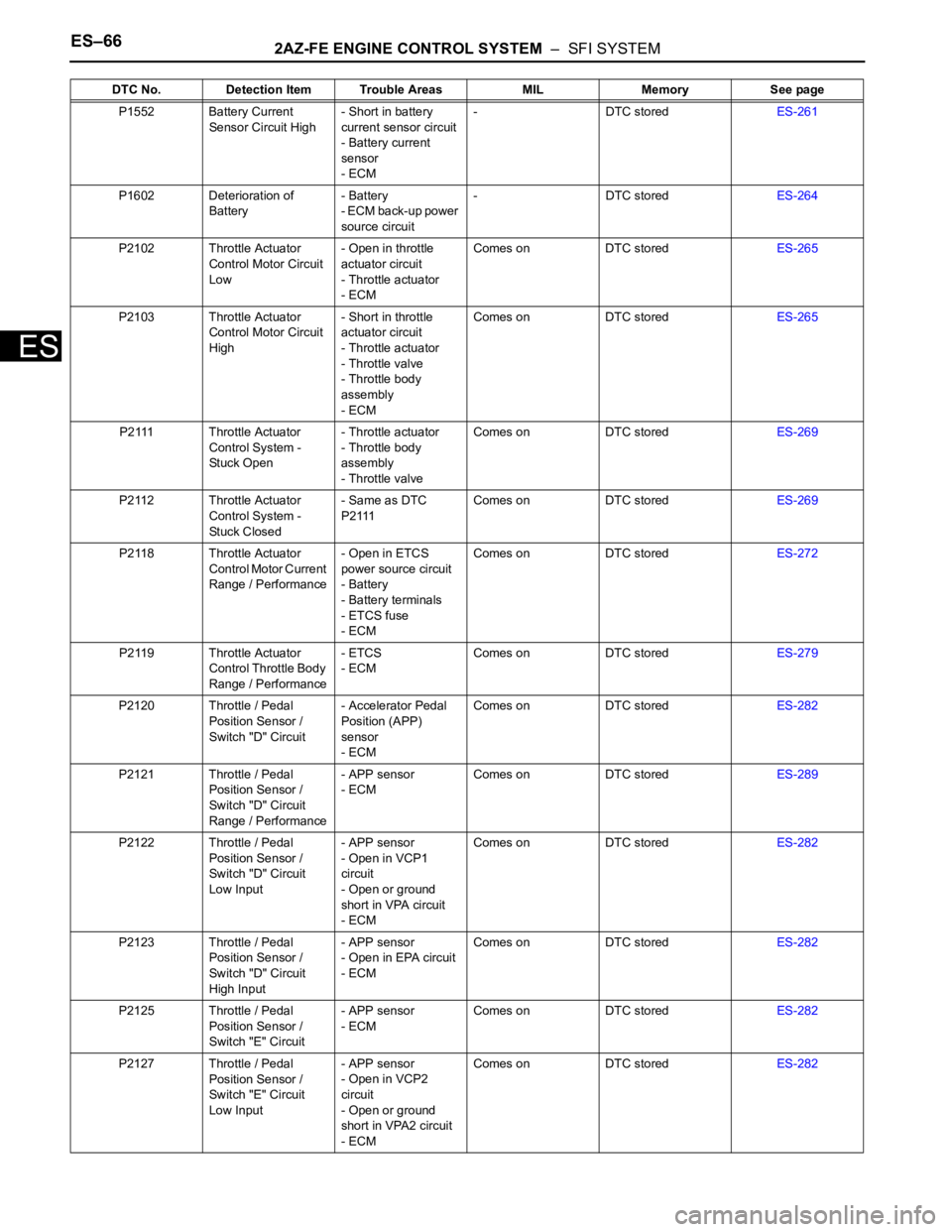
ES–662AZ-FE ENGINE CONTROL SYSTEM – SFI SYSTEM
ES
P1552 Battery Current
Sensor Circuit High- Short in battery
current sensor circuit
- Battery current
sensor
- ECM- DTC storedES-261
P1602 Deterioration of
Battery- Battery
- ECM back-up power
source circuit- DTC storedES-264
P2102 Throttle Actuator
Control Motor Circuit
Low- Open in throttle
actuator circuit
- Throttle actuator
- ECMComes on DTC storedES-265
P2103 Throttle Actuator
Control Motor Circuit
High- Short in throttle
actuator circuit
- Throttle actuator
- Throttle valve
- Throttle body
assembly
- ECMComes on DTC storedES-265
P2111 Throttle Actuator
Control System -
Stuck Open- Throttle actuator
- Throttle body
assembly
- Throttle valveComes on DTC storedES-269
P2112 Throttle Actuator
Control System -
Stuck Closed- Same as DTC
P2111Comes on DTC storedES-269
P2118 Throttle Actuator
Control Motor Current
Range / Performance- Open in ETCS
power source circuit
- Battery
- Battery terminals
- ETCS fuse
- ECMComes on DTC storedES-272
P2119 Throttle Actuator
Control Throttle Body
Range / Performance- ETCS
- ECMComes on DTC storedES-279
P2120 Throttle / Pedal
Position Sensor /
Switch "D" Circuit- Accelerator Pedal
Position (APP)
sensor
- ECMComes on DTC storedES-282
P2121 Throttle / Pedal
Position Sensor /
Switch "D" Circuit
Range / Performance- APP sensor
- ECMComes on DTC storedES-289
P2122 Throttle / Pedal
Position Sensor /
Switch "D" Circuit
Low Input- APP sensor
- Open in VCP1
circuit
- Open or ground
short in VPA circuit
- ECMComes on DTC storedES-282
P2123 Throttle / Pedal
Position Sensor /
Switch "D" Circuit
High Input- APP sensor
- Open in EPA circuit
- ECMComes on DTC storedES-282
P2125 Throttle / Pedal
Position Sensor /
Switch "E" Circuit- APP sensor
- ECMComes on DTC storedES-282
P2127 Throttle / Pedal
Position Sensor /
Switch "E" Circuit
Low Input- APP sensor
- Open in VCP2
circuit
- Open or ground
short in VPA2 circuit
- ECMComes on DTC storedES-282 DTC No. Detection Item Trouble Areas MIL Memory See page
Page 1955 of 2000
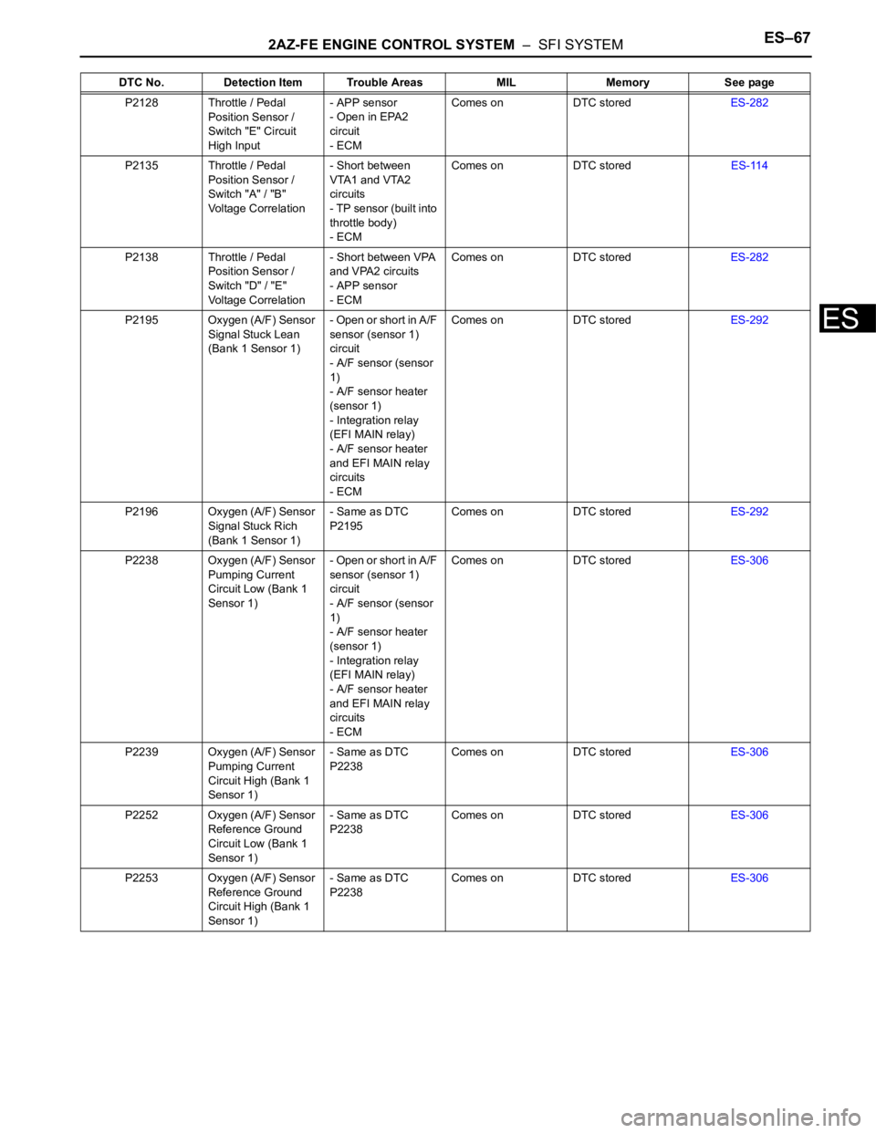
2AZ-FE ENGINE CONTROL SYSTEM – SFI SYSTEMES–67
ES
P2128 Throttle / Pedal
Position Sensor /
Switch "E" Circuit
High Input- APP sensor
- Open in EPA2
circuit
- ECMComes on DTC storedES-282
P2135 Throttle / Pedal
Position Sensor /
Switch "A" / "B"
Voltage Correlation- Short between
VTA1 and VTA2
circuits
- TP sensor (built into
throttle body)
- ECMComes on DTC storedES-114
P2138 Throttle / Pedal
Position Sensor /
Switch "D" / "E"
Voltage Correlation- Short between VPA
and VPA2 circuits
- APP sensor
- ECMComes on DTC storedES-282
P2195 Oxygen (A/F) Sensor
Signal Stuck Lean
(Bank 1 Sensor 1)- Open or short in A/F
sensor (sensor 1)
circuit
- A/F sensor (sensor
1)
- A/F sensor heater
(sensor 1)
- Integration relay
(EFI MAIN relay)
- A/F sensor heater
and EFI MAIN relay
circuits
- ECMComes on DTC storedES-292
P2196 Oxygen (A/F) Sensor
Signal Stuck Rich
(Bank 1 Sensor 1)- Same as DTC
P2195Comes on DTC storedES-292
P2238 Oxygen (A/F) Sensor
Pumping Current
Circuit Low (Bank 1
Sensor 1)- Open or short in A/F
sensor (sensor 1)
circuit
- A/F sensor (sensor
1)
- A/F sensor heater
(sensor 1)
- Integration relay
(EFI MAIN relay)
- A/F sensor heater
and EFI MAIN relay
circuits
- ECMComes on DTC storedES-306
P2239 Oxygen (A/F) Sensor
Pumping Current
Circuit High (Bank 1
Sensor 1)- Same as DTC
P2238Comes on DTC storedES-306
P2252 Oxygen (A/F) Sensor
Reference Ground
Circuit Low (Bank 1
Sensor 1)- Same as DTC
P2238Comes on DTC storedES-306
P2253 Oxygen (A/F) Sensor
Reference Ground
Circuit High (Bank 1
Sensor 1)- Same as DTC
P2238Comes on DTC storedES-306 DTC No. Detection Item Trouble Areas MIL Memory See page
Page 1956 of 2000
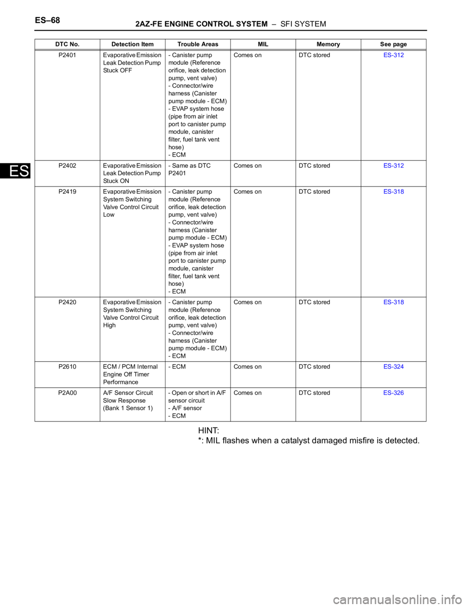
ES–682AZ-FE ENGINE CONTROL SYSTEM – SFI SYSTEM
ES
HINT:
*: MIL flashes when a catalyst damaged misfire is detected.
P2401 Evaporative Emission
Leak Detection Pump
Stuck OFF- Canister pump
module (Reference
orifice, leak detection
pump, vent valve)
- Connector/wire
harness (Canister
pump module - ECM)
- EVAP system hose
(pipe from air inlet
port to canister pump
module, canister
filter, fuel tank vent
hose)
- ECMComes on DTC storedES-312
P2402 Evaporative Emission
Leak Detection Pump
Stuck ON- Same as DTC
P2401Comes on DTC storedES-312
P2419 Evaporative Emission
System Switching
Valve Control Circuit
Low- Canister pump
module (Reference
orifice, leak detection
pump, vent valve)
- Connector/wire
harness (Canister
pump module - ECM)
- EVAP system hose
(pipe from air inlet
port to canister pump
module, canister
filter, fuel tank vent
hose)
- ECMComes on DTC storedES-318
P2420 Evaporative Emission
System Switching
Valve Control Circuit
High- Canister pump
module (Reference
orifice, leak detection
pump, vent valve)
- Connector/wire
harness (Canister
pump module - ECM)
- ECMComes on DTC storedES-318
P2610 ECM / PCM Internal
Engine Off Timer
Performance- ECM Comes on DTC storedES-324
P2A00 A/F Sensor Circuit
Slow Response
(Bank 1 Sensor 1)- Open or short in A/F
sensor circuit
- A/F sensor
- ECMComes on DTC storedES-326 DTC No. Detection Item Trouble Areas MIL Memory See page
Page 1957 of 2000
2AZ-FE ENGINE CONTROL SYSTEM – SFI SYSTEMES–69
ES
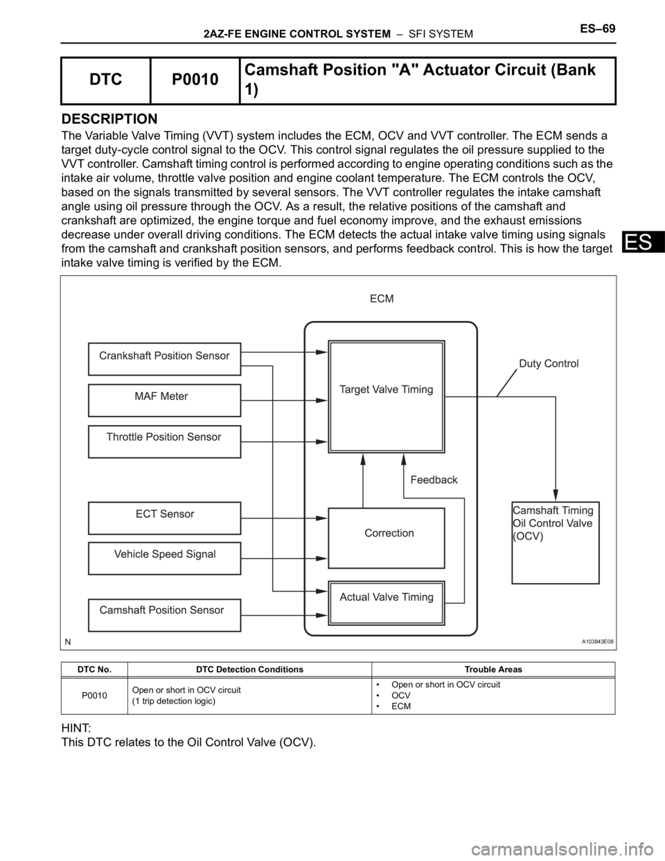
DESCRIPTION
The Variable Valve Timing (VVT) system includes the ECM, OCV and VVT controller. The ECM sends a
target duty-cycle control signal to the OCV. This control signal regulates the oil pressure supplied to the
VVT controller. Camshaft timing control is performed according to engine operating conditions such as the
intake air volume, throttle valve position and engine coolant temperature. The ECM controls the OCV,
based on the signals transmitted by several sensors. The VVT controller regulates the intake camshaft
angle using oil pressure through the OCV. As a result, the relative positions of the camshaft and
crankshaft are optimized, the engine torque and fuel economy improve, and the exhaust emissions
decrease under overall driving conditions. The ECM detects the actual intake valve timing using signals
from the camshaft and crankshaft position sensors, and performs feedback control. This is how the target
intake valve timing is verified by the ECM.
HINT:
This DTC relates to the Oil Control Valve (OCV).
DTC P0010Camshaft Position "A" Actuator Circuit (Bank
1)
DTC No. DTC Detection Conditions Trouble Areas
P0010Open or short in OCV circuit
(1 trip detection logic)• Open or short in OCV circuit
•OCV
•ECM
A103843E08
Page 1958 of 2000

E S –702AZ-FE ENGINE CONTROL SYSTEM – SFI SYSTEM
ES
MONITOR DESCRIPTION
The ECM optimizes the valve timing using the VVT system to control the intake camshaft. The VVT
system includes the ECM, the OCV and the VVT controller. The ECM sends a target duty-cycle control
signal to the OCV. This control signal regulates the oil pressure supplied to the VVT controller. The VVT
controller can advance or retard the intake camshaft.
After the ECM sends the target duty-cycle control signal to the OCV, the ECM monitors the OCV current
to establish an actual duty-cycle. The ECM determines the existence of a malfunction and sets the DTC
when the actual duty-cycle ratio varies from the target duty-cycle ratio.
MONITOR STRATEGY
TYPICAL ENABLING CONDITIONS
TYPICAL MALFUNCTION THRESHOLDS
COMPONENT OPERATING RANGE
Related DTCs P0010: VVT OCV range check
Required Sensors/Components (Main) VVT OCV
Required Sensors/Components (Related) -
Frequency of Operation Continuous
Duration 1 second
MIL Operation Immediate
Sequence of Operation None
Monitor runs whenever following DTCs not present None
All of following conditions met -
Starter OFF
Ignition switch ON
Time after ignition switch OFF to ON 0.5 seconds or more
One of following conditions met -
A. All of following conditions met -
Battery voltage 11 to 13 V
Target duty ratio Less than 70 %
Output signal duty ratio 100 %
B. All of following conditions met -
Battery voltage 13 V or more
Target duty ratio Less than 80 %
Output signal duty ratio 100 %
C. Both of following conditions met -
Current cut status Not cut
Output signal duty ratio 3 % or less
VVT OCV duty ratio 3 to 100 %
Page 1959 of 2000
2AZ-FE ENGINE CONTROL SYSTEM – SFI SYSTEMES–71
ES
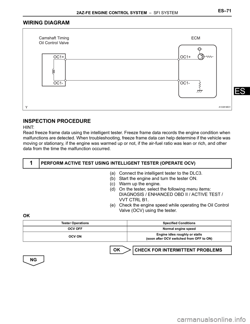
WIRING DIAGRAM
INSPECTION PROCEDURE
HINT:
Read freeze frame data using the intelligent tester. Freeze frame data records the engine condition when
malfunctions are detected. When troubleshooting, freeze frame data can help determine if the vehicle was
moving or stationary, if the engine was warmed up or not, if the air-fuel ratio was lean or rich, and other
data from the time the malfunction occurred.
(a) Connect the intelligent tester to the DLC3.
(b) Start the engine and turn the tester ON.
(c) Warm up the engine.
(d) On the tester, select the following menu items:
DIAGNOSIS / ENHANCED OBD II / ACTIVE TEST /
VVT CTRL B1.
(e) Check the engine speed while operating the Oil Control
Valve (OCV) using the tester.
OK
OK
NG
1PERFORM ACTIVE TEST USING INTELLIGENT TESTER (OPERATE OCV)
A133814E01
Tester Operations Specified Conditions
OCV OFF Normal engine speed
OCV ONEngine idles roughly or stalls
(soon after OCV switched from OFF to ON)
CHECK FOR INTERMITTENT PROBLEMS
Page 1960 of 2000
ES–722AZ-FE ENGINE CONTROL SYSTEM – SFI SYSTEM
ES
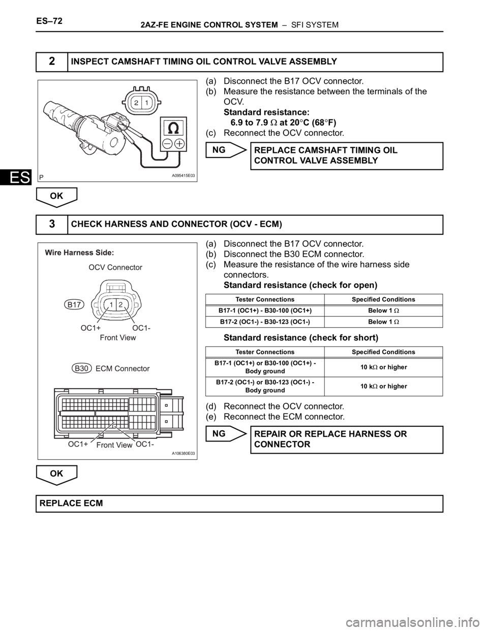
(a) Disconnect the B17 OCV connector.
(b) Measure the resistance between the terminals of the
OCV.
Standard resistance:
6.9 to 7.9
at 20C (68F)
(c) Reconnect the OCV connector.
NG
OK
(a) Disconnect the B17 OCV connector.
(b) Disconnect the B30 ECM connector.
(c) Measure the resistance of the wire harness side
connectors.
Standard resistance (check for open)
Standard resistance (check for short)
(d) Reconnect the OCV connector.
(e) Reconnect the ECM connector.
NG
OK
2INSPECT CAMSHAFT TIMING OIL CONTROL VALVE ASSEMBLY
A095415E03
REPLACE CAMSHAFT TIMING OIL
CONTROL VALVE ASSEMBLY
3CHECK HARNESS AND CONNECTOR (OCV - ECM)
A106380E03
Tester Connections Specified Conditions
B17-1 (OC1+) - B30-100 (OC1+) Below 1
B17-2 (OC1-) - B30-123 (OC1-) Below 1
Tester Connections Specified Conditions
B17-1 (OC1+) or B30-100 (OC1+) -
Body ground10 k
or higher
B17-2 (OC1-) or B30-123 (OC1-) -
Body ground10 k
or higher
REPAIR OR REPLACE HARNESS OR
CONNECTOR
REPLACE ECM