TOYOTA RAV4 2006 Service Repair Manual
Manufacturer: TOYOTA, Model Year: 2006, Model line: RAV4, Model: TOYOTA RAV4 2006Pages: 2000, PDF Size: 45.84 MB
Page 501 of 2000
HO–4HORN – HORN SYSTEM
HO
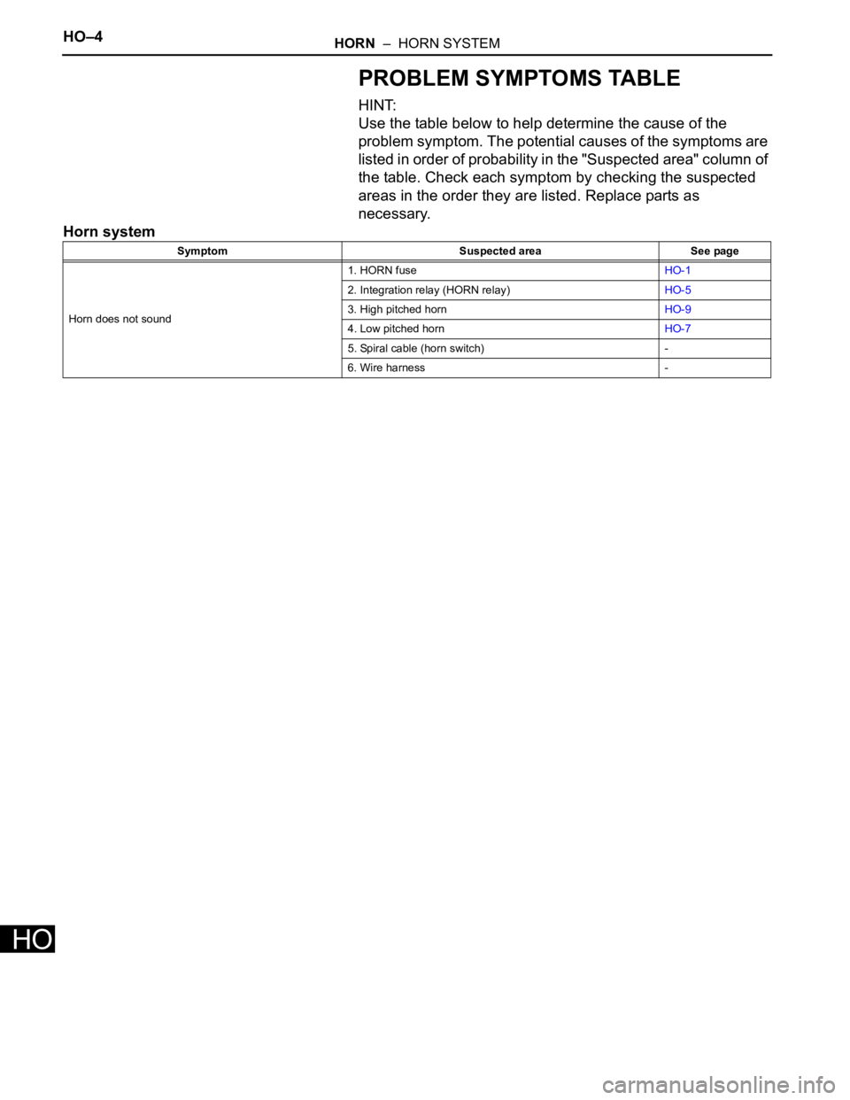
PROBLEM SYMPTOMS TABLE
HINT:
Use the table below to help determine the cause of the
problem symptom. The potential causes of the symptoms are
listed in order of probability in the "Suspected area" column of
the table. Check each symptom by checking the suspected
areas in the order they are listed. Replace parts as
necessary.
Horn system
Symptom Suspected area See page
Horn does not sound1. HORN fuseHO-1
2. Integration relay (HORN relay)HO-5
3. High pitched hornHO-9
4. Low pitched hornHO-7
5. Spiral cable (horn switch) -
6. Wire harness -
Page 502 of 2000
OTHER SYSTEM – CENTER POWER OUTLET SOCKETOT–5
OT
INSTALLATION
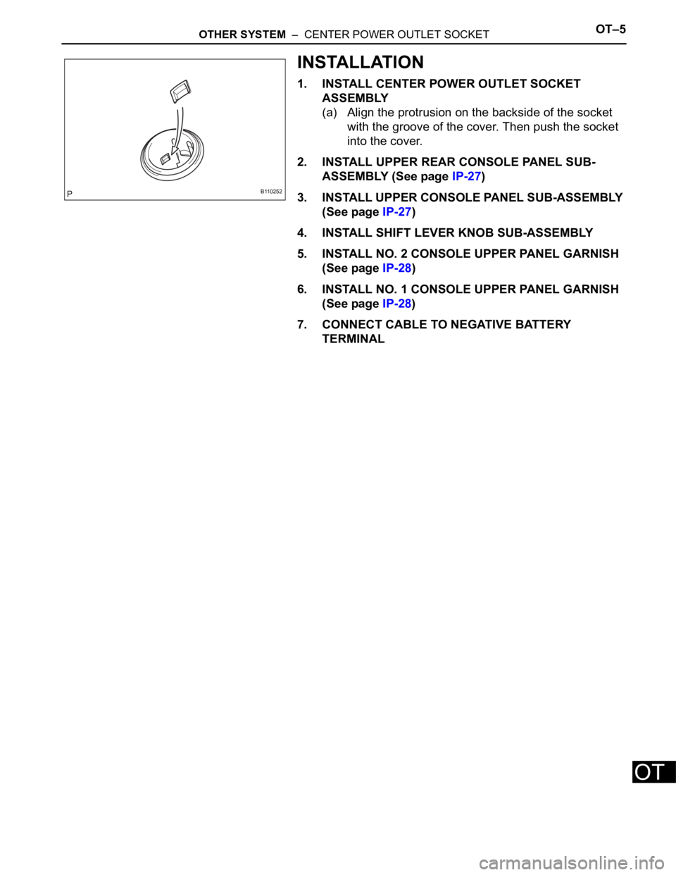
1. INSTALL CENTER POWER OUTLET SOCKET
ASSEMBLY
(a) Align the protrusion on the backside of the socket
with the groove of the cover. Then push the socket
into the cover.
2. INSTALL UPPER REAR CONSOLE PANEL SUB-
ASSEMBLY (See page IP-27)
3. INSTALL UPPER CONSOLE PANEL SUB-ASSEMBLY
(See page IP-27)
4. INSTALL SHIFT LEVER KNOB SUB-ASSEMBLY
5. INSTALL NO. 2 CONSOLE UPPER PANEL GARNISH
(See page IP-28)
6. INSTALL NO. 1 CONSOLE UPPER PANEL GARNISH
(See page IP-28)
7. CONNECT CABLE TO NEGATIVE BATTERY
TERMINAL
B110252
Page 503 of 2000

MIRROR – POWER MIRROR CONTROL SYSTEMMI–3
MI
SYSTEM DESCRIPTION
The outer mirror switch controls the outer rear view mirror LH
and RH.
Page 504 of 2000
MI–4MIRROR – POWER MIRROR CONTROL SYSTEM
MI
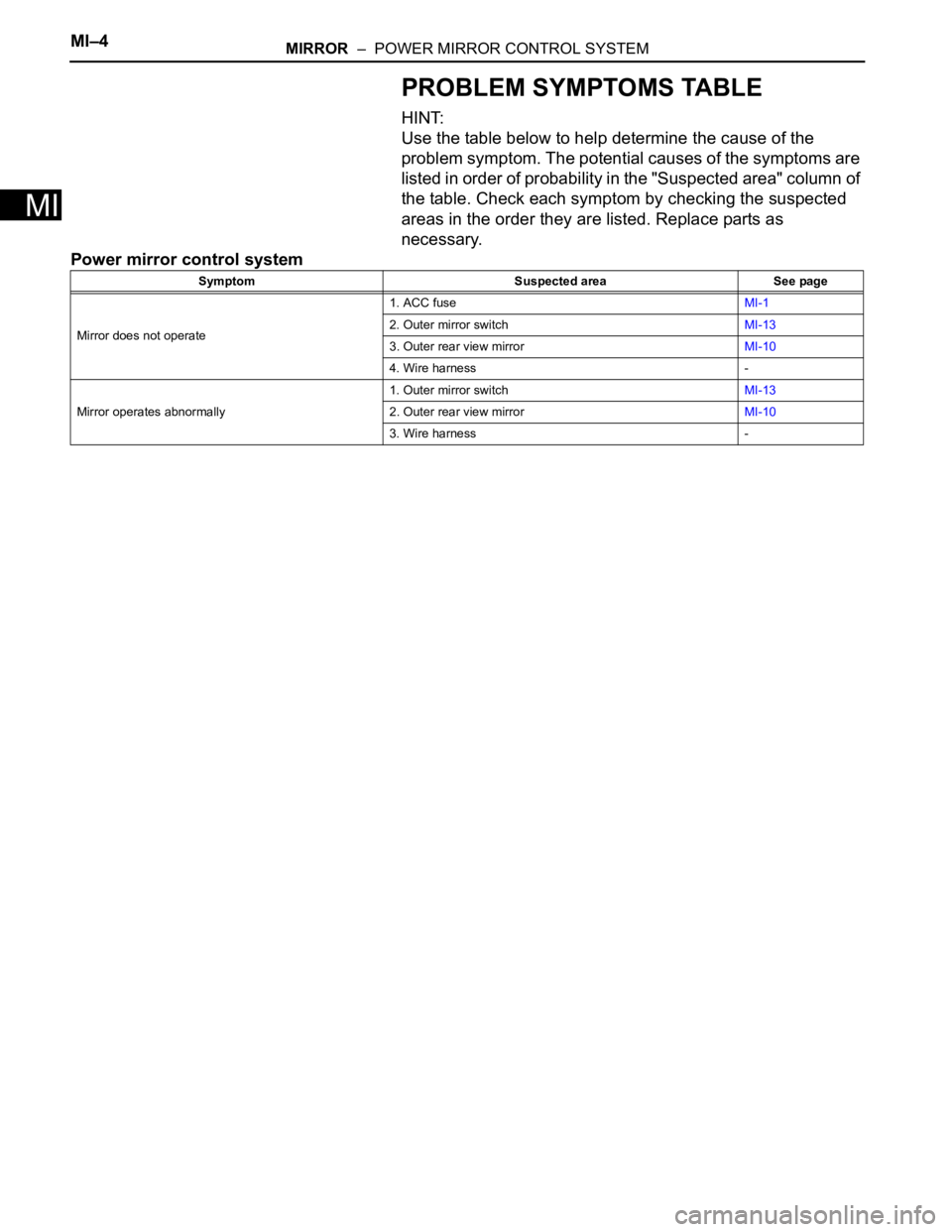
PROBLEM SYMPTOMS TABLE
HINT:
Use the table below to help determine the cause of the
problem symptom. The potential causes of the symptoms are
listed in order of probability in the "Suspected area" column of
the table. Check each symptom by checking the suspected
areas in the order they are listed. Replace parts as
necessary.
Power mirror control system
Symptom Suspected area See page
Mirror does not operate1. ACC fuseMI-1
2. Outer mirror switchMI-13
3. Outer rear view mirrorMI-10
4. Wire harness -
Mirror operates abnormally1. Outer mirror switchMI-13
2. Outer rear view mirrorMI-10
3. Wire harness -
Page 505 of 2000
IP–4INSTRUMENT PANEL – UPPER INSTRUMENT PANEL
IP
REMOVAL
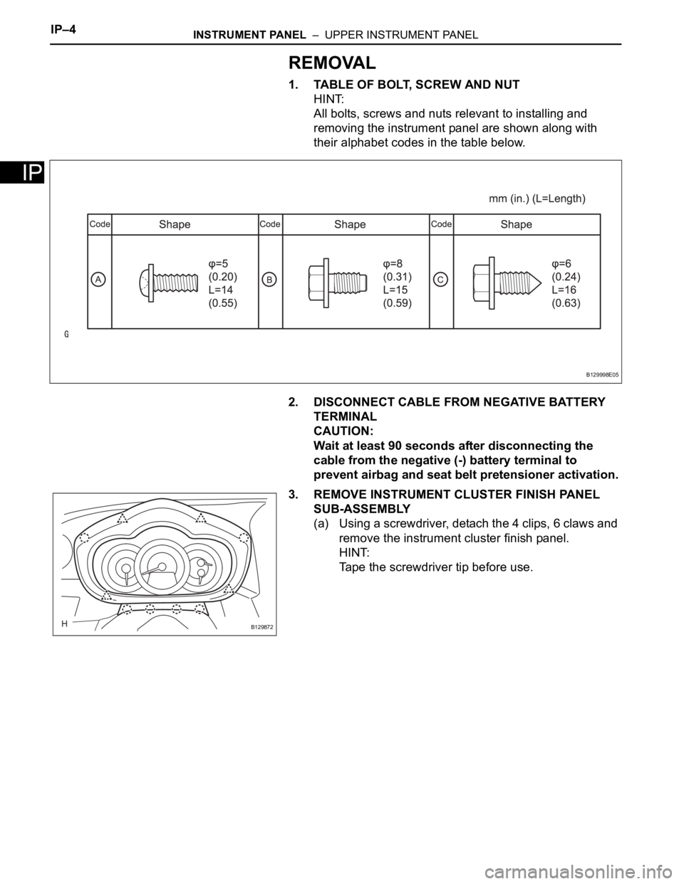
1. TABLE OF BOLT, SCREW AND NUT
HINT:
All bolts, screws and nuts relevant to installing and
removing the instrument panel are shown along with
their alphabet codes in the table below.
2. DISCONNECT CABLE FROM NEGATIVE BATTERY
TERMINAL
CAUTION:
Wait at least 90 seconds after disconnecting the
cable from the negative (-) battery terminal to
prevent airbag and seat belt pretensioner activation.
3. REMOVE INSTRUMENT CLUSTER FINISH PANEL
SUB-ASSEMBLY
(a) Using a screwdriver, detach the 4 clips, 6 claws and
remove the instrument cluster finish panel.
HINT:
Tape the screwdriver tip before use.
B129998E05
B129872
Page 506 of 2000
INSTRUMENT PANEL – UPPER INSTRUMENT PANELIP–5
IP
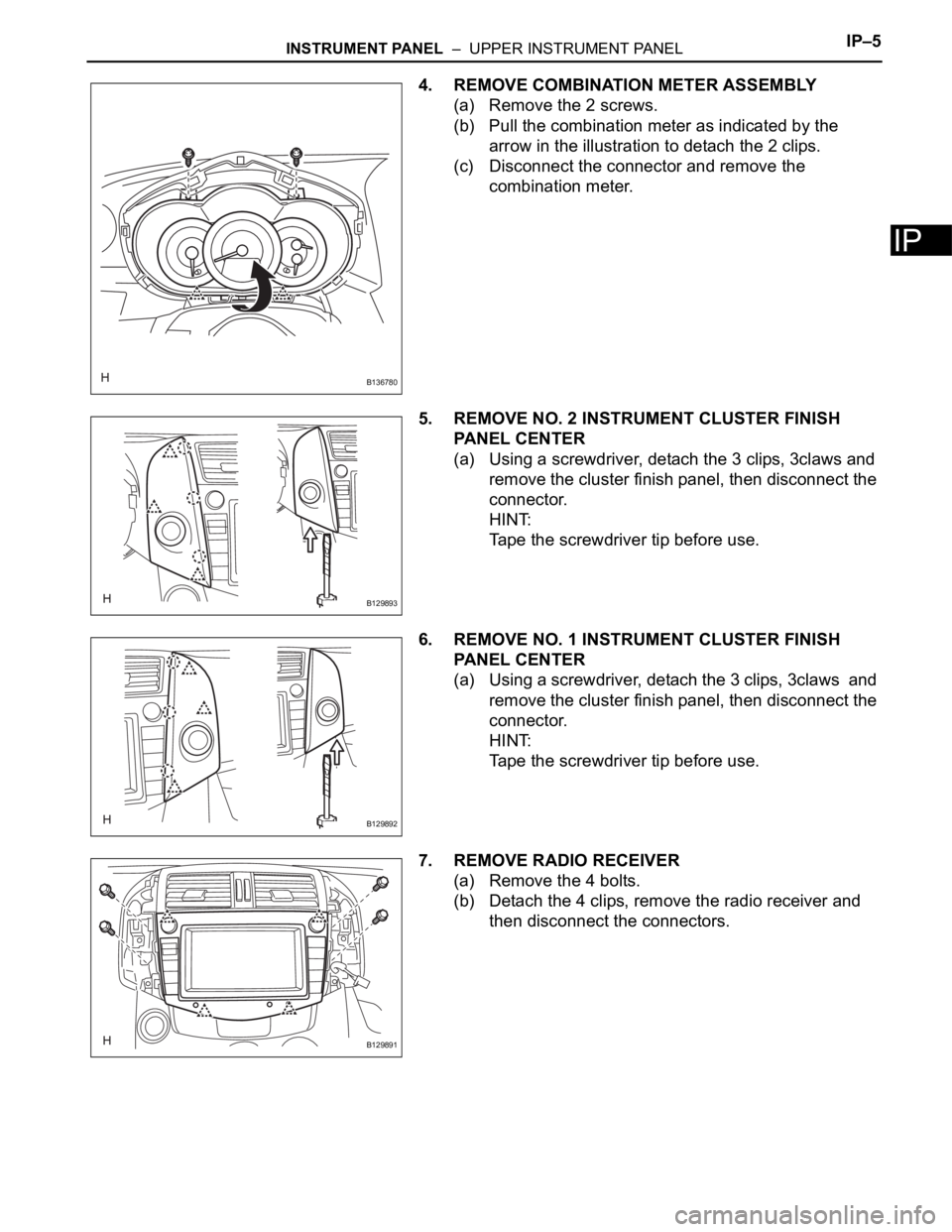
4. REMOVE COMBINATION METER ASSEMBLY
(a) Remove the 2 screws.
(b) Pull the combination meter as indicated by the
arrow in the illustration to detach the 2 clips.
(c) Disconnect the connector and remove the
combination meter.
5. REMOVE NO. 2 INSTRUMENT CLUSTER FINISH
PANEL CENTER
(a) Using a screwdriver, detach the 3 clips, 3claws and
remove the cluster finish panel, then disconnect the
connector.
HINT:
Tape the screwdriver tip before use.
6. REMOVE NO. 1 INSTRUMENT CLUSTER FINISH
PANEL CENTER
(a) Using a screwdriver, detach the 3 clips, 3claws and
remove the cluster finish panel, then disconnect the
connector.
HINT:
Tape the screwdriver tip before use.
7. REMOVE RADIO RECEIVER
(a) Remove the 4 bolts.
(b) Detach the 4 clips, remove the radio receiver and
then disconnect the connectors.
B136780
B129893
B129892
B129891
Page 507 of 2000
IP–6INSTRUMENT PANEL – UPPER INSTRUMENT PANEL
IP
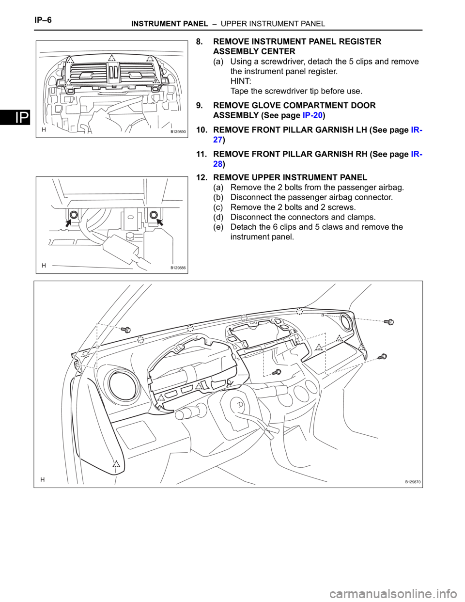
8. REMOVE INSTRUMENT PANEL REGISTER
ASSEMBLY CENTER
(a) Using a screwdriver, detach the 5 clips and remove
the instrument panel register.
HINT:
Tape the screwdriver tip before use.
9. REMOVE GLOVE COMPARTMENT DOOR
ASSEMBLY (See page IP-20)
10. REMOVE FRONT PILLAR GARNISH LH (See page IR-
27)
11. REMOVE FRONT PILLAR GARNISH RH (See page IR-
28)
12. REMOVE UPPER INSTRUMENT PANEL
(a) Remove the 2 bolts from the passenger airbag.
(b) Disconnect the passenger airbag connector.
(c) Remove the 2 bolts and 2 screws.
(d) Disconnect the connectors and clamps.
(e) Detach the 6 clips and 5 claws and remove the
instrument panel.
B129890
B129886
B129870
Page 508 of 2000
SEAT – FRONT POWER SEAT CONTROL SYSTEMSE–3
SE
PROBLEM SYMPTOMS TABLE
HINT:
Use the table below to help determine the cause of the
problem symptom. The potential causes of the symptoms are
listed in order of probability in the "Suspected Area" column
of the table. Check each symptom by checking the suspected
areas in the order they are listed. Replace parts as
necessary.
Front power seat control system
ON-VEHICLE INSPECTION
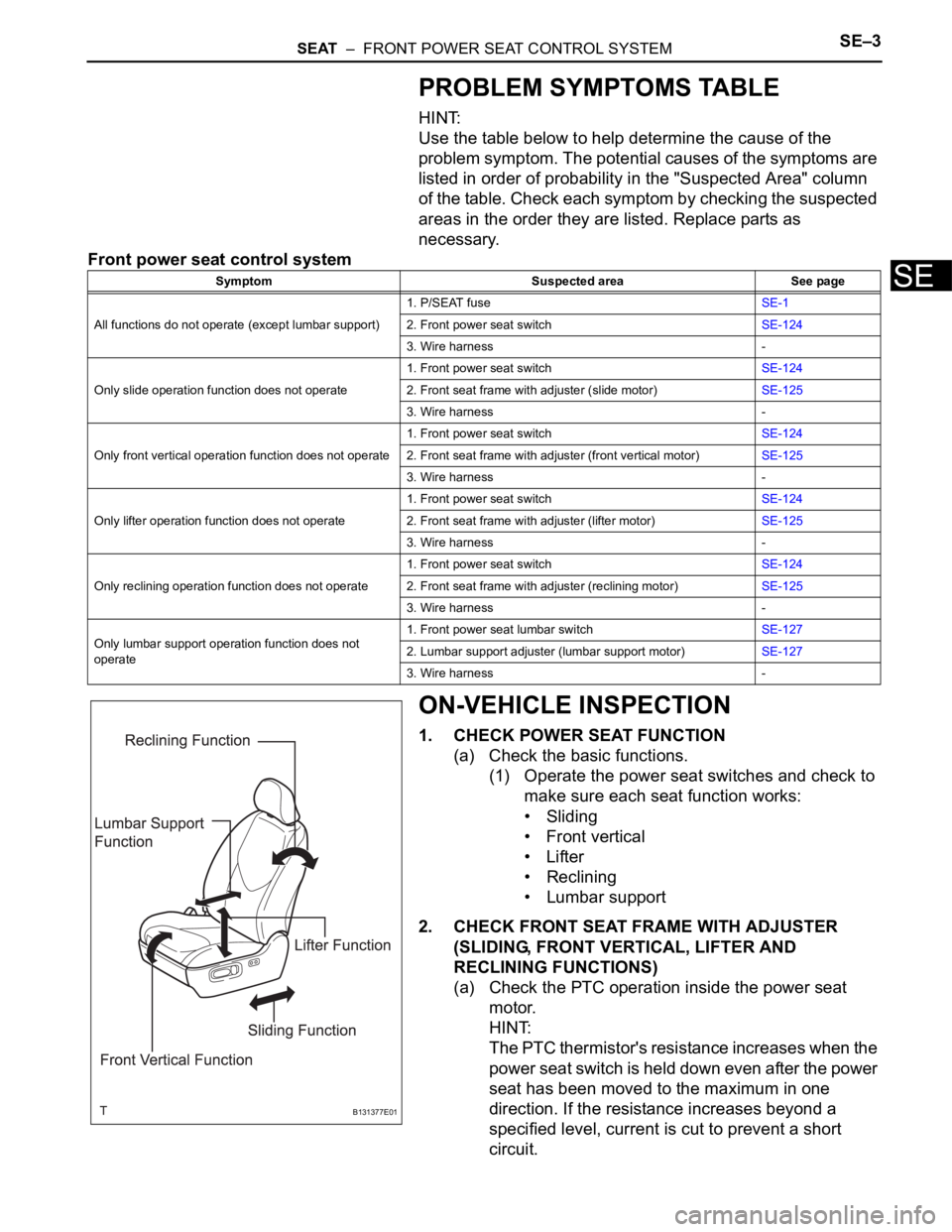
1. CHECK POWER SEAT FUNCTION
(a) Check the basic functions.
(1) Operate the power seat switches and check to
make sure each seat function works:
• Sliding
•Front vertical
•Lifter
• Reclining
• Lumbar support
2. CHECK FRONT SEAT FRAME WITH ADJUSTER
(SLIDING, FRONT VERTICAL, LIFTER AND
RECLINING FUNCTIONS)
(a) Check the PTC operation inside the power seat
motor.
HINT:
The PTC thermistor's resistance increases when the
power seat switch is held down even after the power
seat has been moved to the maximum in one
direction. If the resistance increases beyond a
specified level, current is cut to prevent a short
circuit.
Symptom Suspected area See page
All functions do not operate (except lumbar support)1. P/SEAT fuseSE-1
2. Front power seat switchSE-124
3. Wire harness -
Only slide operation function does not operate1. Front power seat switchSE-124
2. Front seat frame with adjuster (slide motor)SE-125
3. Wire harness -
Only front vertical operation function does not operate1. Front power seat switchSE-124
2. Front seat frame with adjuster (front vertical motor)SE-125
3. Wire harness -
Only lifter operation function does not operate1. Front power seat switchSE-124
2. Front seat frame with adjuster (lifter motor)SE-125
3. Wire harness -
Only reclining operation function does not operate1. Front power seat switchSE-124
2. Front seat frame with adjuster (reclining motor)SE-125
3. Wire harness -
Only lumbar support operation function does not
operate1. Front power seat lumbar switchSE-127
2. Lumbar support adjuster (lumbar support motor)SE-127
3. Wire harness -
B131377E01
Page 509 of 2000

SE–4SEAT – FRONT POWER SEAT CONTROL SYSTEM
SE
NOTICE:
• The inspection should be performed with the
seat installed in the vehicle.
• Perform the 4 steps below for the full range of
motion for each power seat function.
(1) Choose a power seat function. Operate the
power seat switch and move the seat as much
as possible in one direction. Keep the seat in
that position for approximately 60 seconds.
(2) Operate the power seat switch again and
continue to try to move the seat in the same
direction as in the previous step. Measure the
amount of time elapsed before current is
automatically cut (the sound of the motor has
stopped).
Standard:
4 to 90 seconds
(3) After current has been cut, release the power
seat switch and wait for approximately 60
seconds.
(4) Operate the same power seat switch and move
the seat in the opposite direction. Check that
the motor operates.
3. CHECK LUMBAR SUPPORT ADJUSTER ASSEMBLY
(a) Check the PTC operation inside the power seat
motor.
NOTICE:
The inspection should be performed with the
seat installed in the vehicle.
(1) Operate the lumbar support switch and move
the lumbar support to either the foremost or
rearmost position. Keep the seat in that
position for approximately 60 seconds.
(2) Operate the lumbar support switch again and
continue to try to move the lumbar support in
the same direction as in the previous step.
Measure the amount of time elapsed before
current is automatically cut (the sound of the
motor has stopped).
Standard:
4 to 90 seconds
(3) After current has been cut, release the lumbar
support switch and wait for approximately 60
seconds.
(4) Operate the lumbar support switch and move
the seat in the opposite direction. Check that
the motor operates.
Page 510 of 2000
ET–4EXTERIOR – FRONT BUMPER
ET
REMOVAL
1. DISCONNECT CABLE FROM NEGATIVE BATTERY
TERMINAL
CAUTION:
Wait at least 90 seconds after disconnecting the
cable from the negative (-) battery terminal to
prevent airbag and seat belt pretensioner activation.
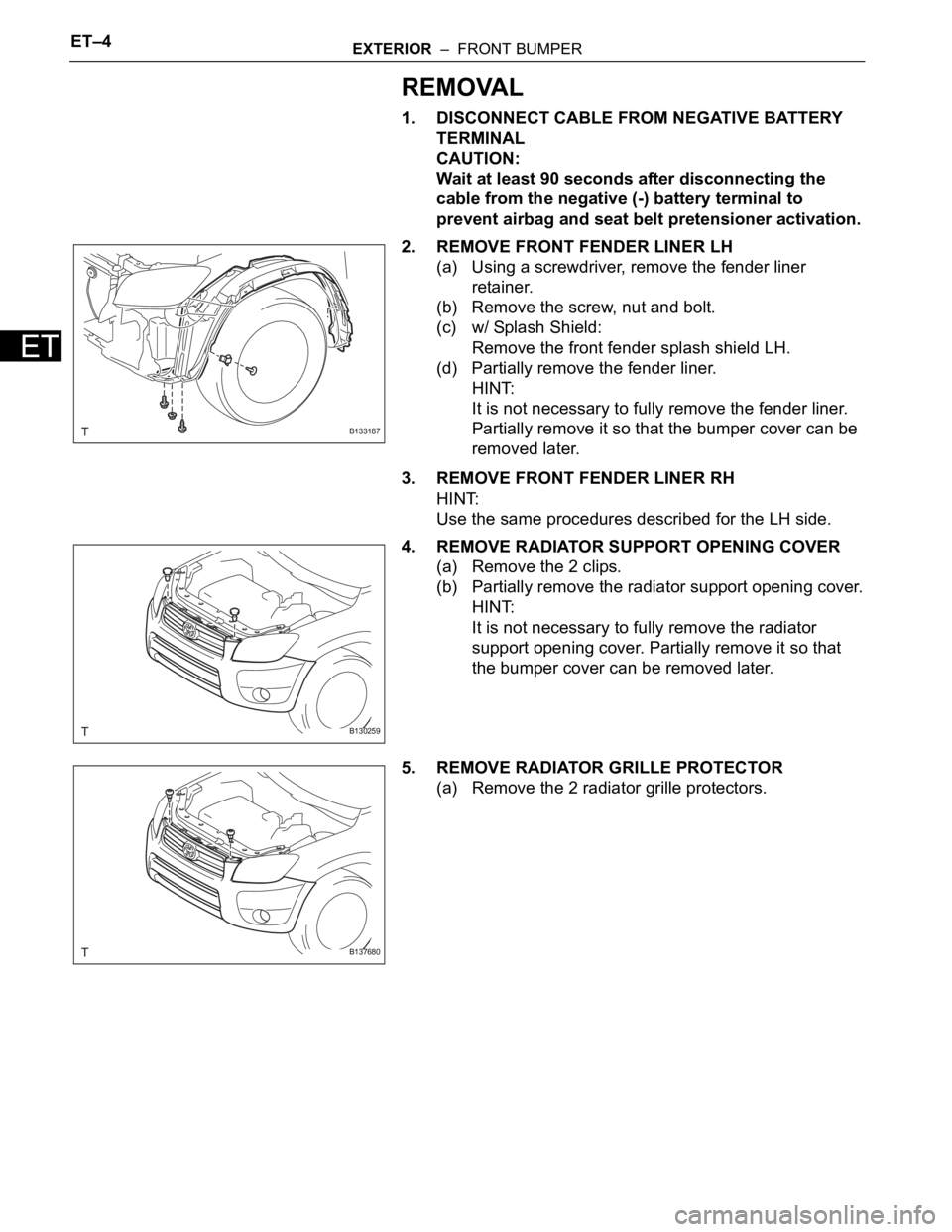
2. REMOVE FRONT FENDER LINER LH
(a) Using a screwdriver, remove the fender liner
retainer.
(b) Remove the screw, nut and bolt.
(c) w/ Splash Shield:
Remove the front fender splash shield LH.
(d) Partially remove the fender liner.
HINT:
It is not necessary to fully remove the fender liner.
Partially remove it so that the bumper cover can be
removed later.
3. REMOVE FRONT FENDER LINER RH
HINT:
Use the same procedures described for the LH side.
4. REMOVE RADIATOR SUPPORT OPENING COVER
(a) Remove the 2 clips.
(b) Partially remove the radiator support opening cover.
HINT:
It is not necessary to fully remove the radiator
support opening cover. Partially remove it so that
the bumper cover can be removed later.
5. REMOVE RADIATOR GRILLE PROTECTOR
(a) Remove the 2 radiator grille protectors.
B133187
B130259
B137680