TOYOTA RAV4 2006 Service Repair Manual
Manufacturer: TOYOTA, Model Year: 2006,
Model line: RAV4,
Model: TOYOTA RAV4 2006
Pages: 2000, PDF Size: 45.84 MB
TOYOTA RAV4 2006 Service Repair Manual
RAV4 2006
TOYOTA
TOYOTA
https://www.carmanualsonline.info/img/14/57463/w960_57463-0.png
TOYOTA RAV4 2006 Service Repair Manual
Trending: engine oil, absorber, turn signal, Brake, instrument cluster, suspension, automatic transmission fluid
Page 531 of 2000
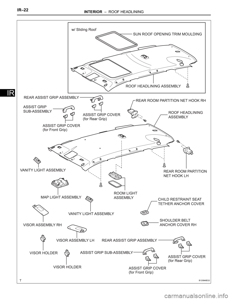
IR–22INTERIOR – ROOF HEADLINING
IR
B129846E02
Page 532 of 2000
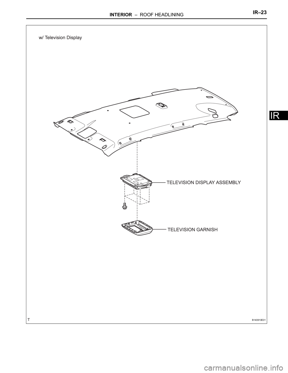
INTERIOR – ROOF HEADLININGIR–23
IR
B140910E01
Page 533 of 2000
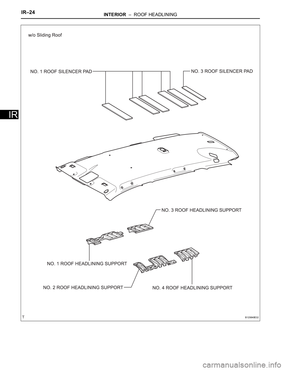
IR–24INTERIOR – ROOF HEADLINING
IR
B129848E02
Page 534 of 2000
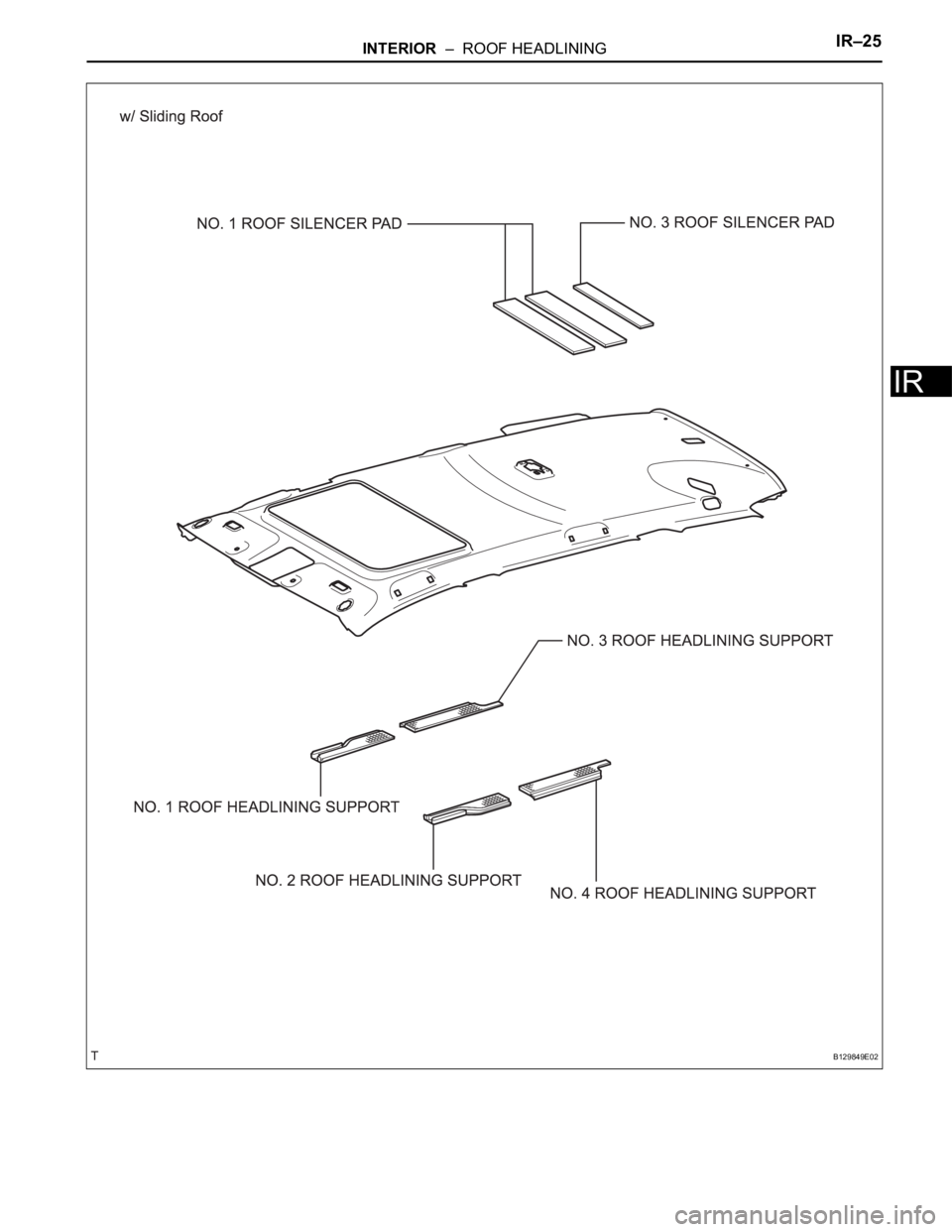
INTERIOR – ROOF HEADLININGIR–25
IR
B129849E02
Page 535 of 2000
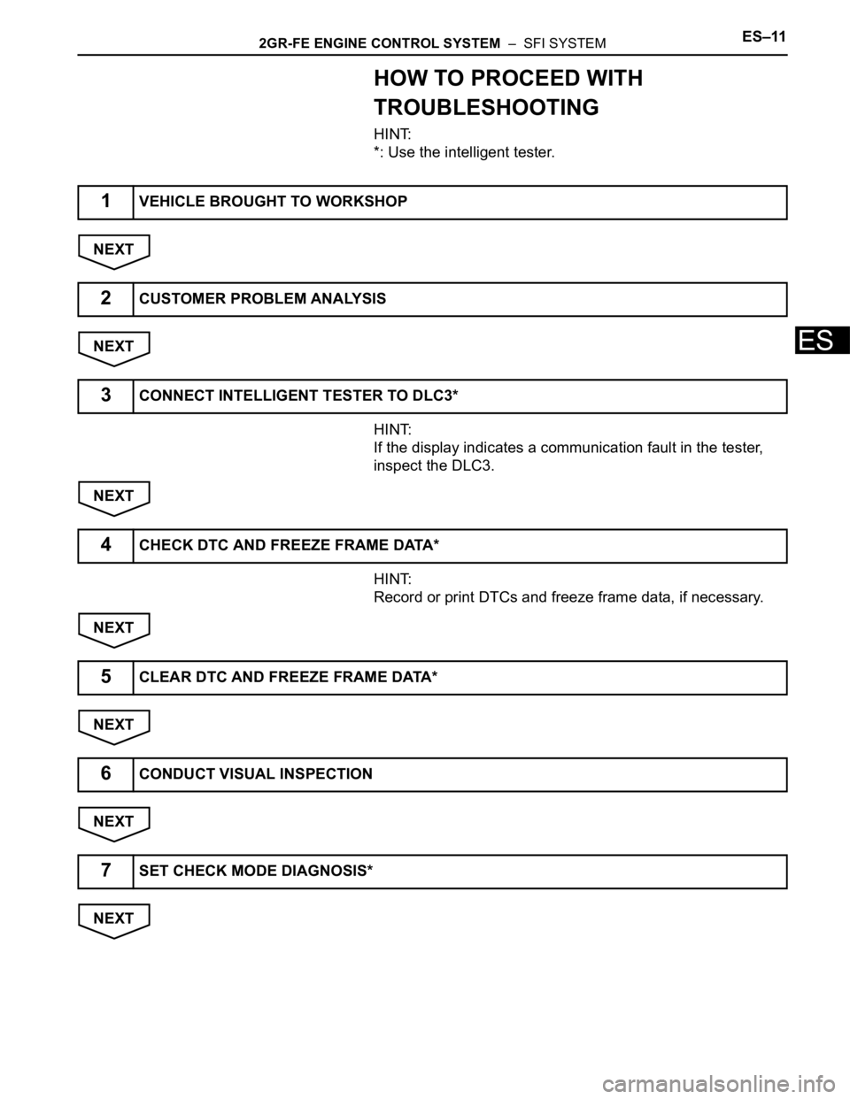
2GR-FE ENGINE CONTROL SYSTEM – SFI SYSTEMES–11
ES
HOW TO PROCEED WITH
TROUBLESHOOTING
HINT:
*: Use the intelligent tester.
NEXT
NEXT
HINT:
If the display indicates a communication fault in the tester,
inspect the DLC3.
NEXT
HINT:
Record or print DTCs and freeze frame data, if necessary.
NEXT
NEXT
NEXT
NEXT
1VEHICLE BROUGHT TO WORKSHOP
2CUSTOMER PROBLEM ANALYSIS
3CONNECT INTELLIGENT TESTER TO DLC3*
4CHECK DTC AND FREEZE FRAME DATA*
5CLEAR DTC AND FREEZE FRAME DATA*
6CONDUCT VISUAL INSPECTION
7SET CHECK MODE DIAGNOSIS*
Page 536 of 2000
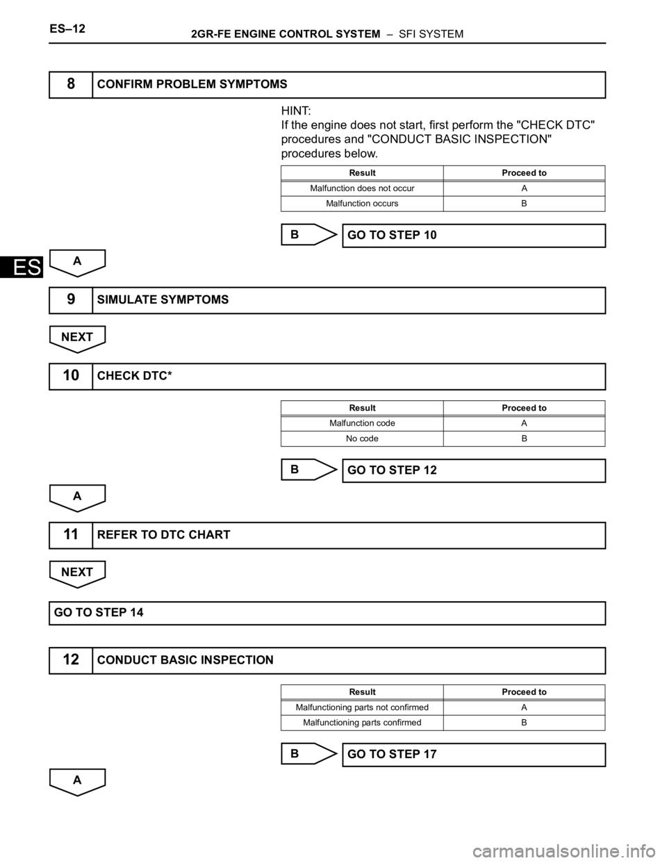
ES–122GR-FE ENGINE CONTROL SYSTEM – SFI SYSTEM
ES
HINT:
If the engine does not start, first perform the "CHECK DTC"
procedures and "CONDUCT BASIC INSPECTION"
procedures below.
B
A
NEXT
B
A
NEXT
B
A
8CONFIRM PROBLEM SYMPTOMS
Result Proceed to
Malfunction does not occur A
Malfunction occurs B
GO TO STEP 10
9SIMULATE SYMPTOMS
10CHECK DTC*
Result Proceed to
Malfunction code A
No code B
GO TO STEP 12
11REFER TO DTC CHART
GO TO STEP 14
12CONDUCT BASIC INSPECTION
Result Proceed to
Malfunctioning parts not confirmed A
Malfunctioning parts confirmed B
GO TO STEP 17
Page 537 of 2000
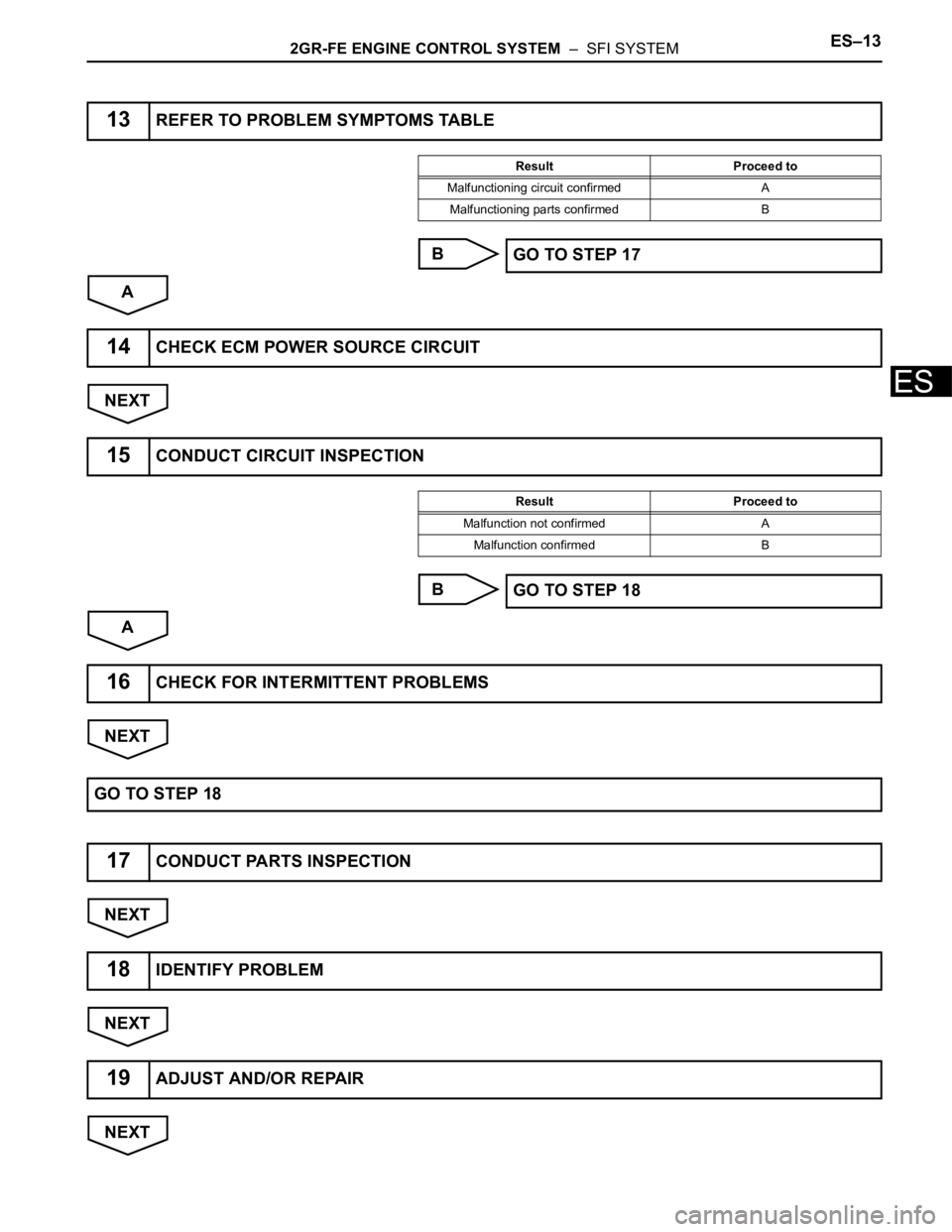
2GR-FE ENGINE CONTROL SYSTEM – SFI SYSTEMES–13
ES
B
A
NEXT
B
A
NEXT
NEXT
NEXT
NEXT
13REFER TO PROBLEM SYMPTOMS TABLE
Result Proceed to
Malfunctioning circuit confirmed A
Malfunctioning parts confirmed B
GO TO STEP 17
14CHECK ECM POWER SOURCE CIRCUIT
15CONDUCT CIRCUIT INSPECTION
Result Proceed to
Malfunction not confirmed A
Malfunction confirmed B
GO TO STEP 18
16CHECK FOR INTERMITTENT PROBLEMS
GO TO STEP 18
17CONDUCT PARTS INSPECTION
18IDENTIFY PROBLEM
19ADJUST AND/OR REPAIR
Page 538 of 2000
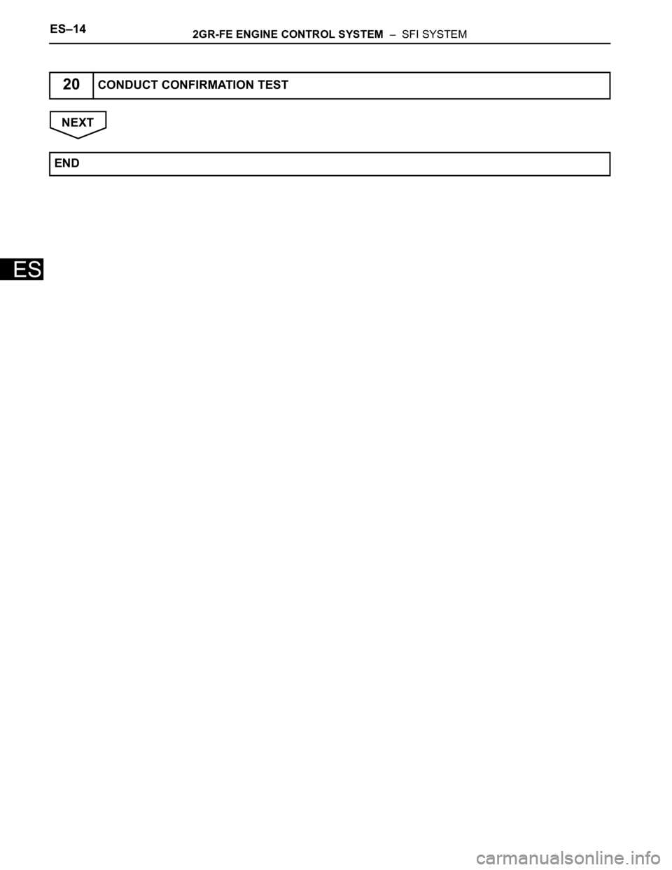
ES–142GR-FE ENGINE CONTROL SYSTEM – SFI SYSTEM
ES
NEXT
20CONDUCT CONFIRMATION TEST
END
Page 539 of 2000
2GR-FE ENGINE CONTROL SYSTEM – SFI SYSTEMES–15
ES
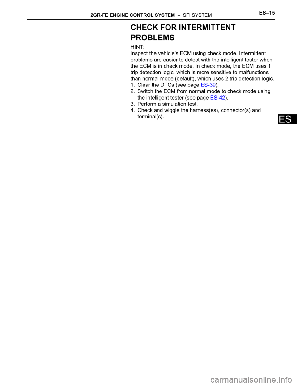
CHECK FOR INTERMITTENT
PROBLEMS
HINT:
Inspect the vehicle's ECM using check mode. Intermittent
problems are easier to detect with the intelligent tester when
the ECM is in check mode. In check mode, the ECM uses 1
trip detection logic, which is more sensitive to malfunctions
than normal mode (default), which uses 2 trip detection logic.
1. Clear the DTCs (see page ES-39).
2. Switch the ECM from normal mode to check mode using
the intelligent tester (see page ES-42).
3. Perform a simulation test.
4. Check and wiggle the harness(es), connector(s) and
terminal(s).
Page 540 of 2000
ES–162GR-FE ENGINE CONTROL SYSTEM – SFI SYSTEM
ES
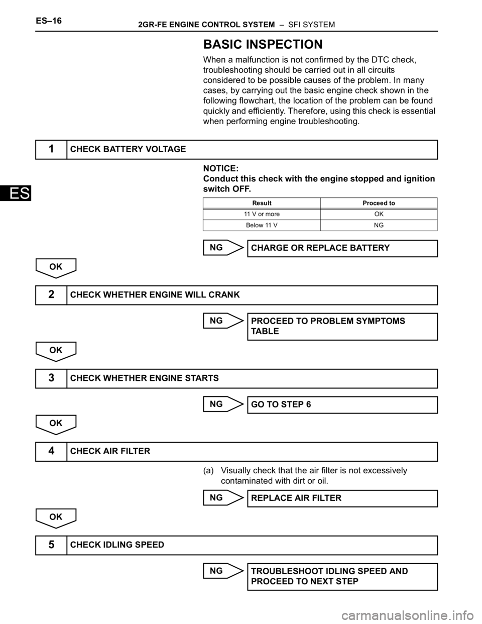
BASIC INSPECTION
When a malfunction is not confirmed by the DTC check,
troubleshooting should be carried out in all circuits
considered to be possible causes of the problem. In many
cases, by carrying out the basic engine check shown in the
following flowchart, the location of the problem can be found
quickly and efficiently. Therefore, using this check is essential
when performing engine troubleshooting.
NOTICE:
Conduct this check with the engine stopped and ignition
switch OFF.
NG
OK
NG
OK
NG
OK
(a) Visually check that the air filter is not excessively
contaminated with dirt or oil.
NG
OK
NG
1CHECK BATTERY VOLTAGE
Result Proceed to
11 V or more OK
Below 11 V NG
CHARGE OR REPLACE BATTERY
2CHECK WHETHER ENGINE WILL CRANK
PROCEED TO PROBLEM SYMPTOMS
TA B L E
3CHECK WHETHER ENGINE STARTS
GO TO STEP 6
4CHECK AIR FILTER
REPLACE AIR FILTER
5CHECK IDLING SPEED
TROUBLESHOOT IDLING SPEED AND
PROCEED TO NEXT STEP
Trending: strut, service indicator, electrical diagram, traction control, layout, height, Rear hub
