TOYOTA SIENNA 2007 Service Repair Manual
Manufacturer: TOYOTA, Model Year: 2007, Model line: SIENNA, Model: TOYOTA SIENNA 2007Pages: 3000, PDF Size: 52.26 MB
Page 281 of 3000

WS–6WINDSHIELD / WINDOWGLASS – POWER WINDOW CONTROL SYSTEM (w/ Jam Protec-
tion Function)
WS
CUSTOMIZE PARAMETERS
HINT:
The following item can be customized.
NOTICE:
• After confirming whether the items requested by the
customer are applicable or not for customization,
perform the customize operation.
• Be sure to record the current settings before
customizing.
• When troubleshooting, make sure that the item in
question is not set to "OFF" as a result of
customization (Example: For the system, "the wireless
function does not operate", first check that the
wireless function is not set to "OFF", then perform
troubleshooting).
POWER WINDOW
DISPLAY (ITEM) DEFAULT CONTENTS SETTING
IG OFF P/W ONAfter ignition switch OFF, power window control permission signal is
outputON / OFF
Page 282 of 3000

WINDSHIELD / WINDOWGLASS – POWER WINDOW CONTROL SYSTEM (w/ Jam Protec-
tion Function)WS–7
WS
INITIALIZATION
NOTICE:
• Resetting the power window motor (initializing the
pulse sensor) is necessary when the battery terminal
is disconnected; when the master switch, wire
harness, power window regulator and power window
motor are replaced or removed/installed; or when the
fuses are replaced. AUTO operation function, jam
protection function and remote operation function via
the power window master switch do not operate
without resetting.
• If the AUTO switch (driver side switch) of the master
switch has been continuously operated for a long
time, the power window motor will stop so that no
additional load can be applied to the motor.
Continuing to operate the switch even after the motor
has stopped will cause the switch to blink while
restricting the AUTO UP/DOWN function and the
remote UP/DOWN function. If this happens, reset the
motor again after several minutes have passed.
• Whenever disconnecting the battery terminal, reset all
the other systems besides the power window control
system.
1. RESET POWER WINDOW REGULATOR MOTOR
(DRIVER SIDE)
(a) Turn the ignition switch ON.
(b) Halfway open the power window by pressing the
power window switch.
(c) Fully pull up the switch until the power window is
fully closed and continue to hold the switch for
approx. 1 second after the power window is fully
closed.
(d) Check that the AUTO UP/DOWN function operates
normally.
If the AUTO UP/DOWN function operates normally,
reset operations have been completed at this time.
If not normal, follow steps below.
(1) Disconnect the negative battery terminal for 10
seconds.
(2) Connect the battery terminal.
(3) Perform the above steps (a) to (d) again.
HINT:
If operation is normal, reset operations have
been completed at this time. If not normal, follow
steps (4) to (7).
(4) Turn the ignition switch ON.
(5) Halfway open the power window by pressing the
power window switch.
(6) Fully pull up the switch until the power window is
fully closed and continue to hold the switch for
approx. 12 seconds after the power window is
fully closed.
(7) Check that the AUTO UP/DOWN function
operates normally.
Page 283 of 3000
WS–66WINDSHIELD / WINDOWGLASS – WINDOW DEFOGGER SYSTEM
WS
PROBLEM SYMPTOMS TABLE
WINDOW DEFOGGER SYSTEM
ON-VEHICLE INSPECTION
1. INSPECT BACK WINDOW (DEFOGGER WIRE)
NOTICE:
• When cleaning the glass, wipe the glass along the
wire using a soft and dry cloth. Take care not to
damage the wires.
• Do not use detergents or glass cleaners including
abrasive ingredients.
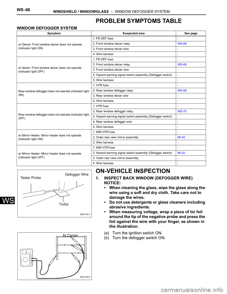
• When measuring voltage, wrap a piece of tin foil
around the tip of the negative probe and press the
foil against the wire with your finger, as shown in
the illustration.
(a) Turn the ignition switch ON.
(b) Turn the defogger switch ON.
Symptom Suspected area See page
w/ Deicer: Front window deicer does not operate.
(indicator light ON)1. FR DEF fuse -
2. Front window deicer relayWS-69
3. Front window deicer wire -
4. Wire harness -
w/ deicer: Front window deicer does not operate.
(indicator light OFF)1. FR DEF fuse -
2. Front window deicer relayWS-69
3. Front window deicer wire -
4. Hazard warning signal switch assembly (Defogger switch) -
5. Wire harness -
Rear window defogger does not operate (indicator light
ON)1. HTR fuse -
2. Rear window defogger relayWS-69
3. Rear window deicer wire -
4. Wire harness -
Rear window defogger does not operate (indicator light
OFF)1. HTR fuse -
2. Rear window defogger relayWS-70
3. Hazard warning signal switch assembly (Defogger switch) -
4. Rear window defogger wire -
5. Wire harness -
w/ Mirror Heater: Mirror heater does not operate
(indicator light ON)1. MIR HTR fuse -
2. Outer rear view mirror assemblyMI-42
3. Wire harness -
w/ Mirror Heater: Mirror heater does not operate
(indicator light OFF)1. MIR HTR fuse -
2. Hazard warning signal switch assembly (Defogger switch)MI-42
3. Outer rear view mirror assembly -
4. Wire harness -
B066134E11
B063720E01
Page 284 of 3000
WINDSHIELD / WINDOWGLASS – WINDOW DEFOGGER SYSTEMWS–67
WS
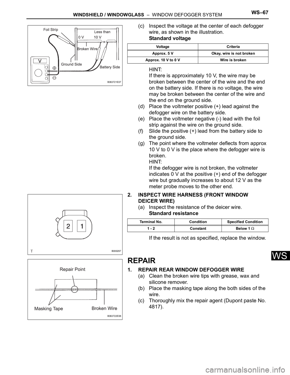
(c) Inspect the voltage at the center of each defogger
wire, as shown in the illustration.
Standard voltage
HINT:
If there is approximately 10 V, the wire may be
broken between the center of the wire and the end
on the battery side. If there is no voltage, the wire
may be broken between the center of the wire and
the end on the ground side.
(d) Place the voltmeter positive (+) lead against the
defogger wire on the battery side.
(e) Place the voltmeter negative (-) lead with the foil
strip against the wire on the ground side.
(f) Slide the positive (+) lead from the battery side to
the ground side.
(g) The point where the voltmeter deflects from approx
10 V to 0 V is the place where the defogger wire is
broken.
HINT:
If the defogger wire is not broken, the voltmeter
indicates 0 V at the positive (+) end of the defogger
wire but gradually increases to about 12 V as the
meter probe moves to the other end.
2. INSPECT WIRE HARNESS (FRONT WINDOW
DEICER WIRE)
(a) Inspect the resistance of the deicer wire.
Standard resistance
If the result is not as specified, replace the window.
REPAIR
1. REPAIR REAR WINDOW DEFOGGER WIRE
(a) Clean the broken wire tips with grease, wax and
silicone remover.
(b) Place the masking tape along the both sides of the
wire.
(c) Thoroughly mix the repair agent (Dupont paste No.
4817).
B063721E07
Voltage Criteria
Approx. 5 V Okay, wire is not broken
Approx. 10 V to 0 V Wire is broken
B069297
Terminal No. Condition Specified Condition
1 - 2 Constant Below 1
B063722E08
Page 285 of 3000
WS–68WINDSHIELD / WINDOWGLASS – WINDOW DEFOGGER SYSTEM
WS
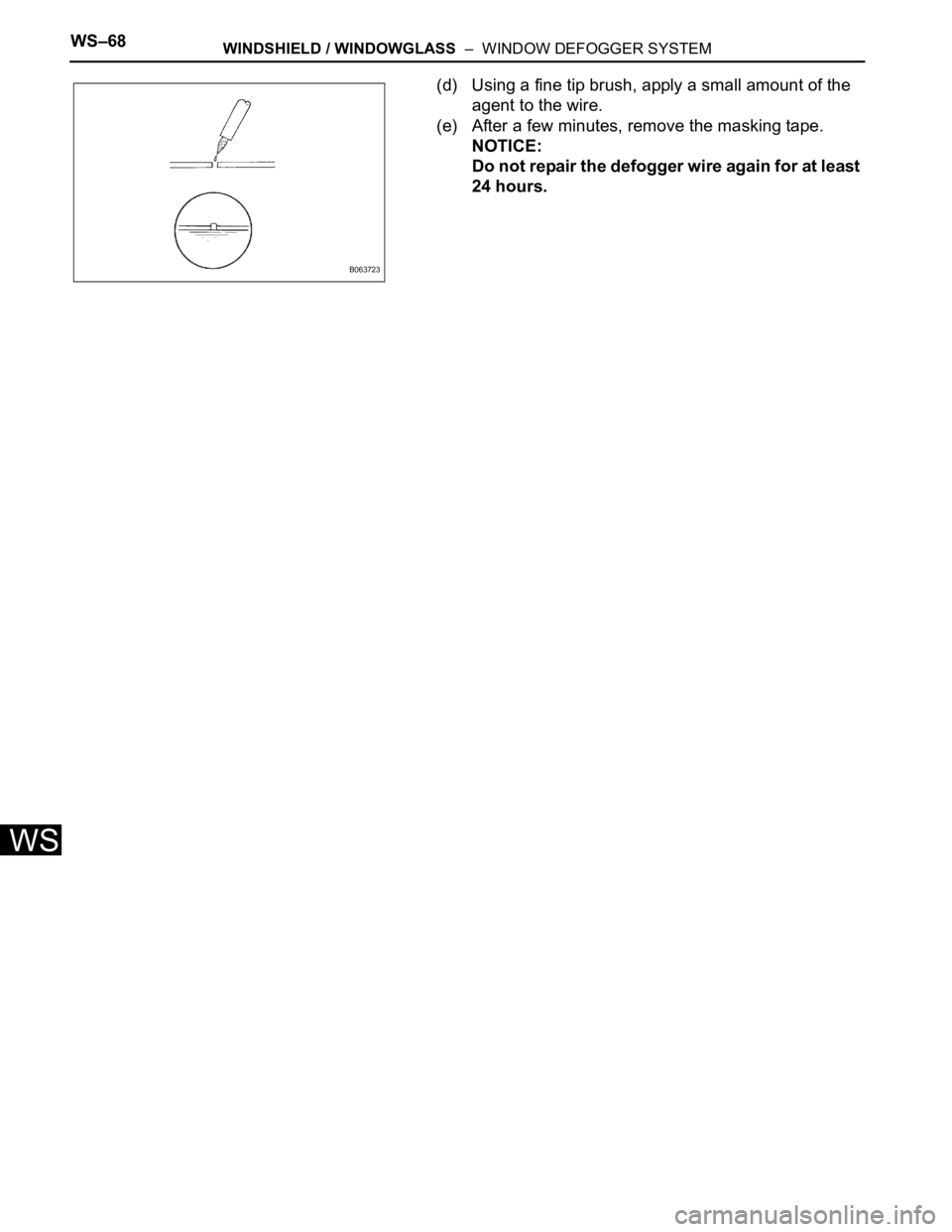
(d) Using a fine tip brush, apply a small amount of the
agent to the wire.
(e) After a few minutes, remove the masking tape.
NOTICE:
Do not repair the defogger wire again for at least
24 hours.
B063723
Page 286 of 3000
MIRROR – POWER MIRROR CONTROL SYSTEM (w/ Memory)MI–3
MI
SYSTEM DIAGRAM
B112551E02
Page 287 of 3000
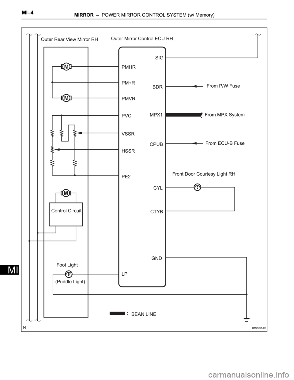
MI–4MIRROR – POWER MIRROR CONTROL SYSTEM (w/ Memory)
MI
B112552E02
Page 288 of 3000
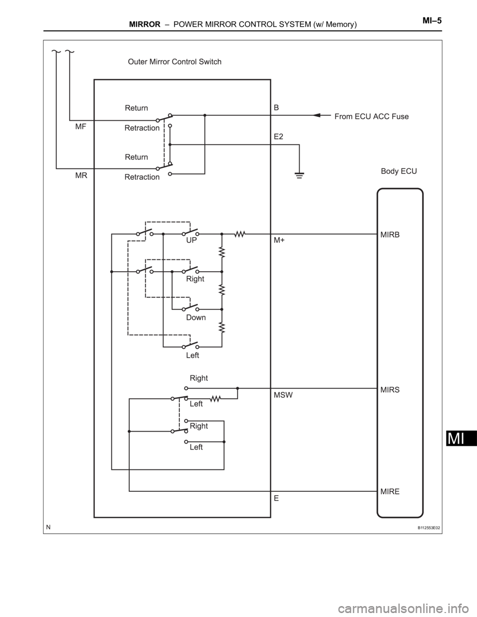
MIRROR – POWER MIRROR CONTROL SYSTEM (w/ Memory)MI–5
MI
B112553E02
Page 289 of 3000
INSTRUMENT PANEL – INSTRUMENT PANEL SAFETY PADIP–5
IP
REMOVAL
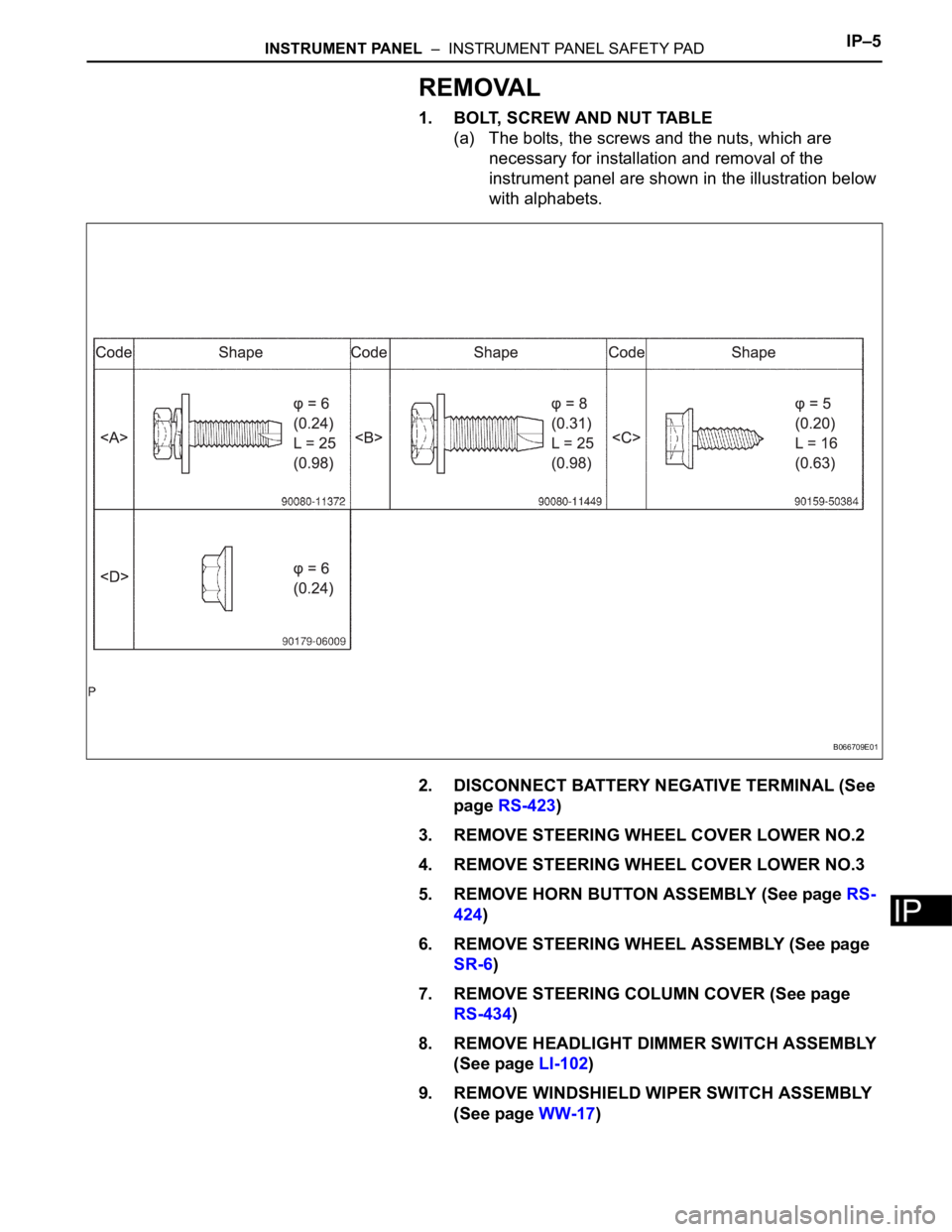
1. BOLT, SCREW AND NUT TABLE
(a) The bolts, the screws and the nuts, which are
necessary for installation and removal of the
instrument panel are shown in the illustration below
with alphabets.
2. DISCONNECT BATTERY NEGATIVE TERMINAL (See
page RS-423)
3. REMOVE STEERING WHEEL COVER LOWER NO.2
4. REMOVE STEERING WHEEL COVER LOWER NO.3
5. REMOVE HORN BUTTON ASSEMBLY (See page RS-
424)
6. REMOVE STEERING WHEEL ASSEMBLY (See page
SR-6)
7. REMOVE STEERING COLUMN COVER (See page
RS-434)
8. REMOVE HEADLIGHT DIMMER SWITCH ASSEMBLY
(See page LI-102)
9. REMOVE WINDSHIELD WIPER SWITCH ASSEMBLY
(See page WW-17)
B066709E01
Page 290 of 3000
IP–6INSTRUMENT PANEL – INSTRUMENT PANEL SAFETY PAD
IP
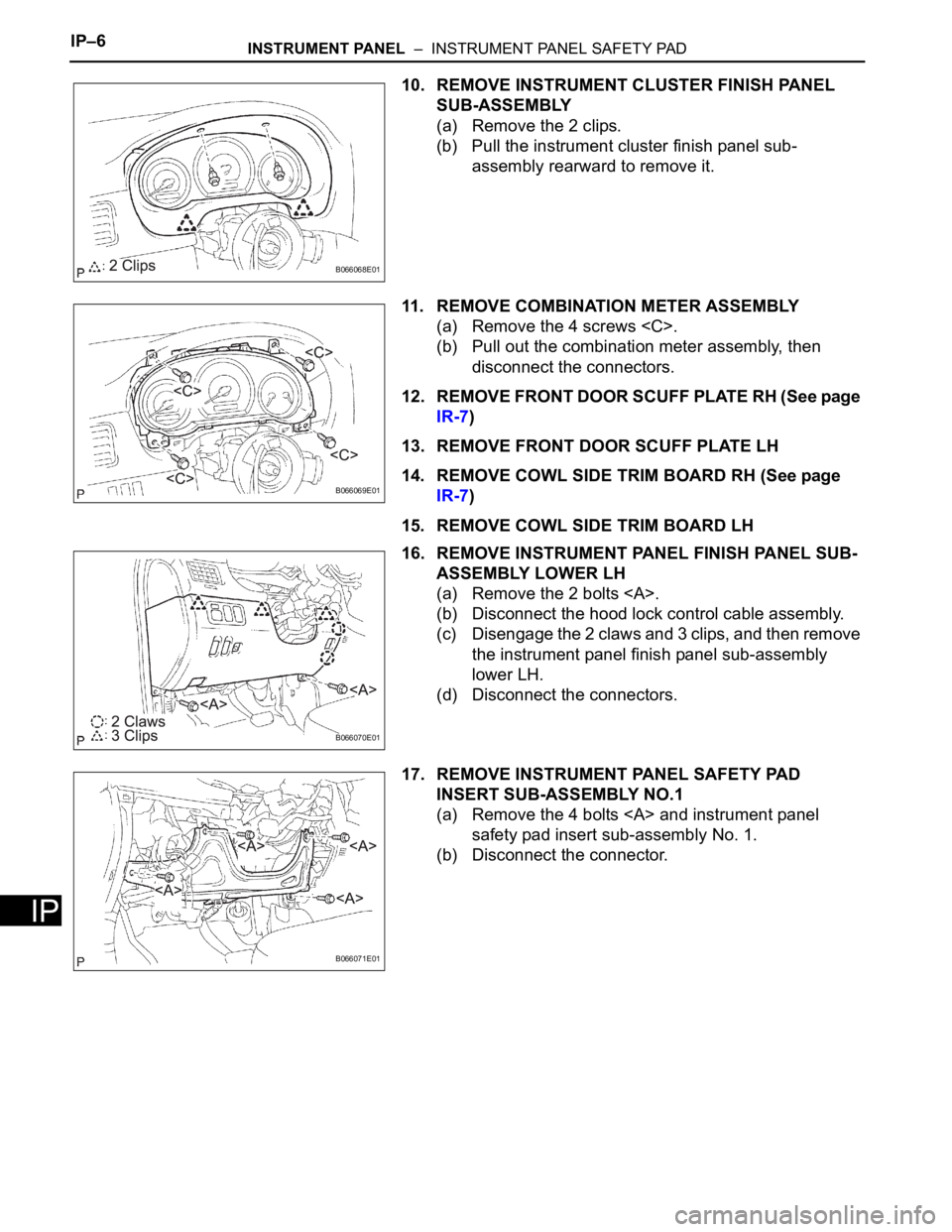
10. REMOVE INSTRUMENT CLUSTER FINISH PANEL
SUB-ASSEMBLY
(a) Remove the 2 clips.
(b) Pull the instrument cluster finish panel sub-
assembly rearward to remove it.
11. REMOVE COMBINATION METER ASSEMBLY
(a) Remove the 4 screws
(b) Pull out the combination meter assembly, then
disconnect the connectors.
12. REMOVE FRONT DOOR SCUFF PLATE RH (See page
IR-7)
13. REMOVE FRONT DOOR SCUFF PLATE LH
14. REMOVE COWL SIDE TRIM BOARD RH (See page
IR-7)
15. REMOVE COWL SIDE TRIM BOARD LH
16. REMOVE INSTRUMENT PANEL FINISH PANEL SUB-
ASSEMBLY LOWER LH
(a) Remove the 2 bolts .
(b) Disconnect the hood lock control cable assembly.
(c) Disengage the 2 claws and 3 clips, and then remove
the instrument panel finish panel sub-assembly
lower LH.
(d) Disconnect the connectors.
17. REMOVE INSTRUMENT PANEL SAFETY PAD
INSERT SUB-ASSEMBLY NO.1
(a) Remove the 4 bolts and instrument panel
safety pad insert sub-assembly No. 1.
(b) Disconnect the connector.
B066068E01
B066069E01
B066070E01
B066071E01