TOYOTA SIENNA 2007 Service Repair Manual
Manufacturer: TOYOTA, Model Year: 2007, Model line: SIENNA, Model: TOYOTA SIENNA 2007Pages: 3000, PDF Size: 52.26 MB
Page 311 of 3000
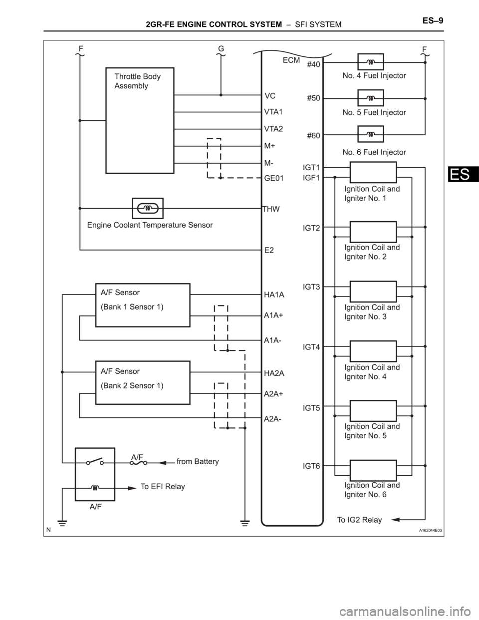
2GR-FE ENGINE CONTROL SYSTEM – SFI SYSTEMES–9
ES
A162044E03
Page 312 of 3000
ENGINE HOOD / DOOR – POWER SLIDE DOOR SYSTEMED–5
ED
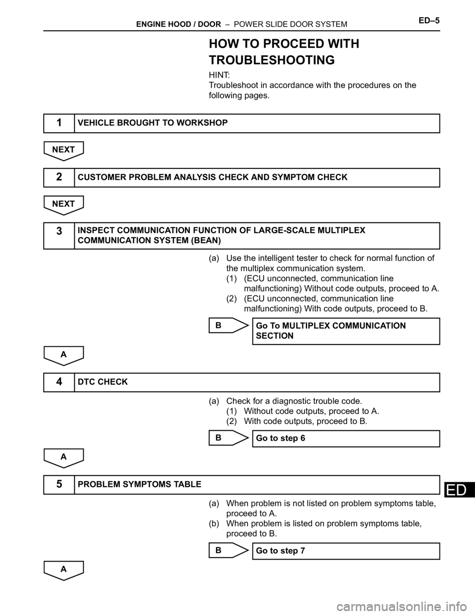
HOW TO PROCEED WITH
TROUBLESHOOTING
HINT:
Troubleshoot in accordance with the procedures on the
following pages.
NEXT
NEXT
(a) Use the intelligent tester to check for normal function of
the multiplex communication system.
(1) (ECU unconnected, communication line
malfunctioning) Without code outputs, proceed to A.
(2) (ECU unconnected, communication line
malfunctioning) With code outputs, proceed to B.
B
A
(a) Check for a diagnostic trouble code.
(1) Without code outputs, proceed to A.
(2) With code outputs, proceed to B.
B
A
(a) When problem is not listed on problem symptoms table,
proceed to A.
(b) When problem is listed on problem symptoms table,
proceed to B.
B
A
1VEHICLE BROUGHT TO WORKSHOP
2CUSTOMER PROBLEM ANALYSIS CHECK AND SYMPTOM CHECK
3INSPECT COMMUNICATION FUNCTION OF LARGE-SCALE MULTIPLEX
COMMUNICATION SYSTEM (BEAN)
Go To MULTIPLEX COMMUNICATION
SECTION
4DTC CHECK
Go to step 6
5PROBLEM SYMPTOMS TABLE
Go to step 7
Page 313 of 3000
ED–6ENGINE HOOD / DOOR – POWER SLIDE DOOR SYSTEM
ED
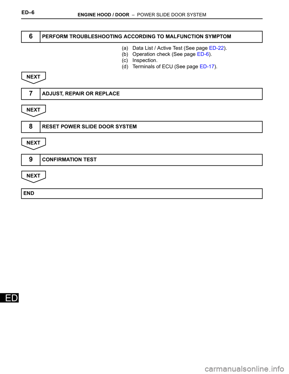
(a) Data List / Active Test (See page ED-22).
(b) Operation check (See page ED-6).
(c) Inspection.
(d) Terminals of ECU (See page ED-17).
NEXT
NEXT
NEXT
NEXT
6PERFORM TROUBLESHOOTING ACCORDING TO MALFUNCTION SYMPTOM
7ADJUST, REPAIR OR REPLACE
8RESET POWER SLIDE DOOR SYSTEM
9CONFIRMATION TEST
END
Page 314 of 3000
ES–102GR-FE ENGINE CONTROL SYSTEM – SFI SYSTEM
ES
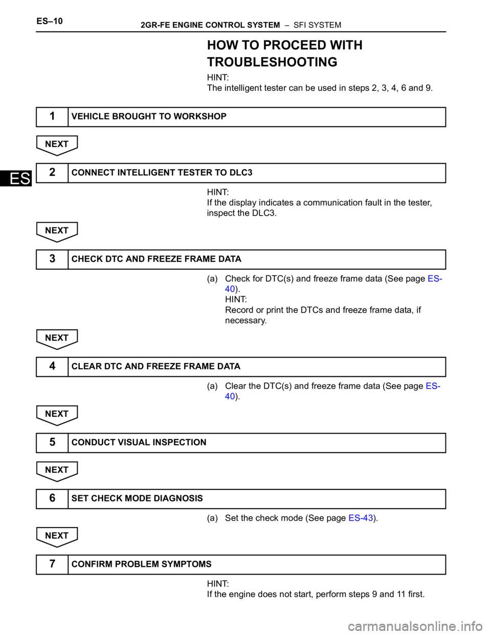
HOW TO PROCEED WITH
TROUBLESHOOTING
HINT:
The intelligent tester can be used in steps 2, 3, 4, 6 and 9.
NEXT
HINT:
If the display indicates a communication fault in the tester,
inspect the DLC3.
NEXT
(a) Check for DTC(s) and freeze frame data (See page ES-
40).
HINT:
Record or print the DTCs and freeze frame data, if
necessary.
NEXT
(a) Clear the DTC(s) and freeze frame data (See page ES-
40).
NEXT
NEXT
(a) Set the check mode (See page ES-43).
NEXT
HINT:
If the engine does not start, perform steps 9 and 11 first.
1VEHICLE BROUGHT TO WORKSHOP
2CONNECT INTELLIGENT TESTER TO DLC3
3CHECK DTC AND FREEZE FRAME DATA
4CLEAR DTC AND FREEZE FRAME DATA
5CONDUCT VISUAL INSPECTION
6SET CHECK MODE DIAGNOSIS
7CONFIRM PROBLEM SYMPTOMS
Page 315 of 3000
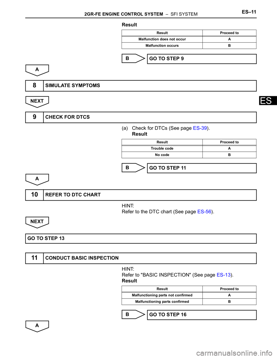
2GR-FE ENGINE CONTROL SYSTEM – SFI SYSTEMES–11
ES
Result
B
A
NEXT
(a) Check for DTCs (See page ES-39).
Result
B
A
HINT:
Refer to the DTC chart (See page ES-56).
NEXT
HINT:
Refer to "BASIC INSPECTION" (See page ES-13).
Result
B
A
Result Proceed to
Malfunction does not occur A
Malfunction occurs B
GO TO STEP 9
8SIMULATE SYMPTOMS
9CHECK FOR DTCS
Result Proceed to
Trouble code A
No code B
GO TO STEP 11
10REFER TO DTC CHART
GO TO STEP 13
11CONDUCT BASIC INSPECTION
Result Proceed to
Malfunctioning parts not confirmed A
Malfunctioning parts confirmed B
GO TO STEP 16
Page 316 of 3000
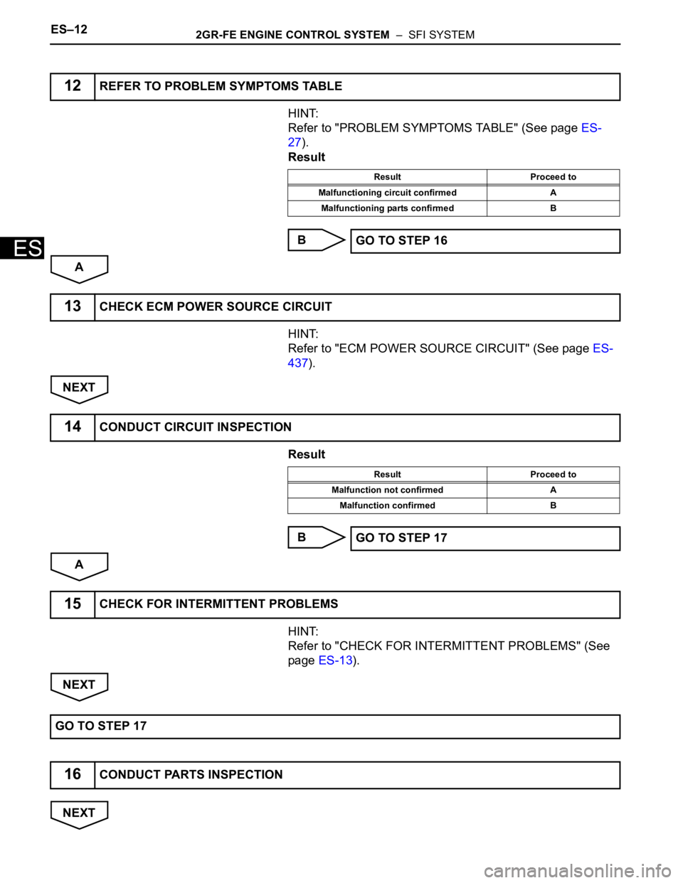
ES–122GR-FE ENGINE CONTROL SYSTEM – SFI SYSTEM
ES
HINT:
Refer to "PROBLEM SYMPTOMS TABLE" (See page ES-
27).
Result
B
A
HINT:
Refer to "ECM POWER SOURCE CIRCUIT" (See page ES-
437).
NEXT
Result
B
A
HINT:
Refer to "CHECK FOR INTERMITTENT PROBLEMS" (See
page ES-13).
NEXT
NEXT
12REFER TO PROBLEM SYMPTOMS TABLE
Result Proceed to
Malfunctioning circuit confirmed A
Malfunctioning parts confirmed B
GO TO STEP 16
13CHECK ECM POWER SOURCE CIRCUIT
14CONDUCT CIRCUIT INSPECTION
Result Proceed to
Malfunction not confirmed A
Malfunction confirmed B
GO TO STEP 17
15CHECK FOR INTERMITTENT PROBLEMS
GO TO STEP 17
16CONDUCT PARTS INSPECTION
Page 317 of 3000
2GR-FE ENGINE CONTROL SYSTEM – SFI SYSTEMES–13
ES
NEXT
NEXT
NEXT
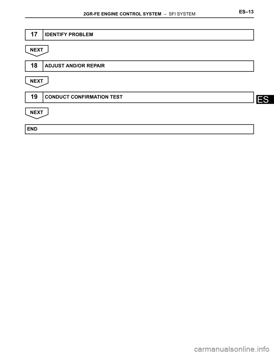
17IDENTIFY PROBLEM
18ADJUST AND/OR REPAIR
19CONDUCT CONFIRMATION TEST
END
Page 318 of 3000

2GR-FE ENGINE CONTROL SYSTEM – SFI SYSTEMES–1
ES
SFI SYSTEM
PRECAUTION
1. INITIALIZATION
NOTICE:
• Perform RESET MEMORY (AT initialization) when
replacing the automatic transaxle assembly, engine
assembly or ECM (See page AX-16).
• Perform REGISTRATION (VIN registration) when
replacing the ECM (See page ES-15).
HINT:
Initialization cannot be completed by only removing the
battery.
2. FOR USING INTELLIGENT TESTER
CAUTION:
Observe the following items for safety reasons:
• Before using the tester, read the instruction
manual.
• Prevent the tester cable from being caught on the
pedals, shift lever and steering wheel when
driving with the tester connected to the vehicle.
• When driving the vehicle for testing purposes
using the tester, two persons are required. One is
for driving the vehicle, and the other operates the
tester.
3. FOR USING BATTERY DURING INSPECTION
(a) While using the battery during inspection, do not
bring the positive and negative tester probes too
close to each other as a short circuit may occur.
4. COOLING FAN SYSTEM
NOTICE:
• When the ignition switch is turned off and the engine
temperature is high, the cooling fans may operate for
approximately 3 minutes.
• After turning the ignition switch off, keep hands and
objects away from the fans when they are operating.
HINT:
If all of the following are met for a certain period of time during
a few minute period immediately before the engine is
stopped, the electric fans will continue to operate for 3
minutes after the engine is stopped. This is performed to
ensure restartability and stabilize idle speed.
– The intelligent tester indicates a very high coolant
temperature.
– The intelligent tester indicates a high outside air
temperature.
– The vehicle has been driven under high load (driving on an
uphill or equivalent).
The following sensors are used for this control:
– Coolant temperature sensor
– Outside air temperature sensor
–MAF sensor
– Vehicle speed sensors
Page 319 of 3000

ES–22GR-FE ENGINE CONTROL SYSTEM – SFI SYSTEM
ES
DEFINITION OF TERMS
Terms Definitions
Monitor Description Description of what ECM monitors and how to detect malfunctions (monitoring purpose and details).
Related DTCs A group of diagnostic trouble codes that are output by ECM based on the same malfunction detection logic.
Typical Enabling
ConditionsPreconditions that allow ECM to detect malfunction.
With all preconditions satisfied, ECM sets DTC when monitored value(s) exceeds malfunction threshold(s).
Sequence of OperationOrder of monitor priority, applied if multiple sensors and components are involved in single malfunction detection
process.
Each sensor and component monitored in turn and not monitored until previous detection operation is completed.
Required Sensors /
ComponentsSensors and components used by ECM to detect each malfunction.
Frequency of OperationNumber of times ECM checks for each malfunction during each driving cycle.
"Once per driving cycle" means ECM performs checks for that malfunction only once in single driving cycle.
"Continuous" means ECM performs checks for that malfunction whenever enabling conditions are met.
DurationMinimum time for which ECM must detect continuous deviation in monitored value(s) in order to set DTC. Timing
begins when typical enabling conditions are met.
Malfunction Thresholds Values, beyond which, ECM determines malfunctions exist and sets DTCs.
MIL OperationTiming of MIL illumination after defect is detected.
"Immediate" means ECM illuminates MIL as soon as malfunction is detected.
"2 driving cycles" means ECM illuminates MIL if the same malfunction is detected twice during the next sequential
driving cycle.
Page 320 of 3000

ES–2522GR-FE ENGINE CONTROL SYSTEM – SFI SYSTEM
ES
DESCRIPTION
The exhaust camshaft's Variable Valve Timing (VVT) sensor consists of a magnet and MRE (Magneto
Resistance Element).
The exhaust camshaft has a sensor plate with 3 teeth on its outer circumference.
When the exhaust camshaft rotates, changes occur in the air gaps between the 3 teeth and MRE, which
affects the magnet. As a result, the resistance of the MRE material fluctuates. The VVT sensor converts
the exhaust camshaft rotation data to pulse signals, uses the pulse signals to determine the camshaft
angle, and sends it to the ECM.
MONITOR DESCRIPTION
If no signal is transmitted by the VVT (for exhaust camshaft) sensor despite the engine revolving, or the
rotations of the exhaust camshaft and the crankshaft are not synchronized, the ECM interprets this as a
malfunction of the sensor.
DTC P0365 Camshaft Position Sensor "B" Circuit (Bank 1)
DTC P0367Camshaft Position Sensor "B" Circuit Low
Input (Bank 1)
DTC P0368Camshaft Position Sensor "B" Circuit High
Input (Bank 1)
DTC P0390 Camshaft Position Sensor "B" Circuit (Bank 2)
DTC P0392Camshaft Position Sensor "B" Circuit Low
Input (Bank 2)
DTC P0393Camshaft Position Sensor "B" Circuit High
Input (Bank 2)
DTC No. DTC Detection Condition Trouble Area
P0365
P0390• Input voltage to ECM remains 0.3 V or less, or 4.7
V or higher for more than 5 seconds, when 2 or
more seconds have elapsed after turning ignition
switch ON position
(1 trip detection logic)
• No VVT sensor signal to ECM during cranking
(1 trip detection logic)• Open or short in VVT sensor for exhaust camshaft
circuit
• VVT sensor for exhaust camshaft
• Exhaust camshaft
• Jumped tooth of timing chain
•ECM
P0367
P0392Output voltage of VVT sensor is 0.3 V or less for 5
seconds
(1 trip detection logic)• Open or short in VVT sensor for exhaust camshaft
circuit
• VVT sensor for exhaust camshaft
• Exhaust camshaft
• Jumped tooth of timing chain
•ECM
P0368
P0393Output voltage of VVT sensor is 4.7 V or more for 5
seconds
(1 trip detection logic)• Open or short in VVT sensor for exhaust camshaft
circuit
• VVT sensor for exhaust camshaft
• Exhaust camshaft
• Jumped tooth of timing chain
•ECM