ACURA NSX 1991 Service Repair Manual
Manufacturer: ACURA, Model Year: 1991,
Model line: NSX,
Model: ACURA NSX 1991
Pages: 1640, PDF Size: 60.48 MB
ACURA NSX 1991 Service Repair Manual
NSX 1991
ACURA
ACURA
https://www.carmanualsonline.info/img/32/56988/w960_56988-0.png
ACURA NSX 1991 Service Repair Manual
Trending: catalytic converter, OBD port, wheel bolts, fuse chart, radio antenna, electrical wiring, length
Page 831 of 1640
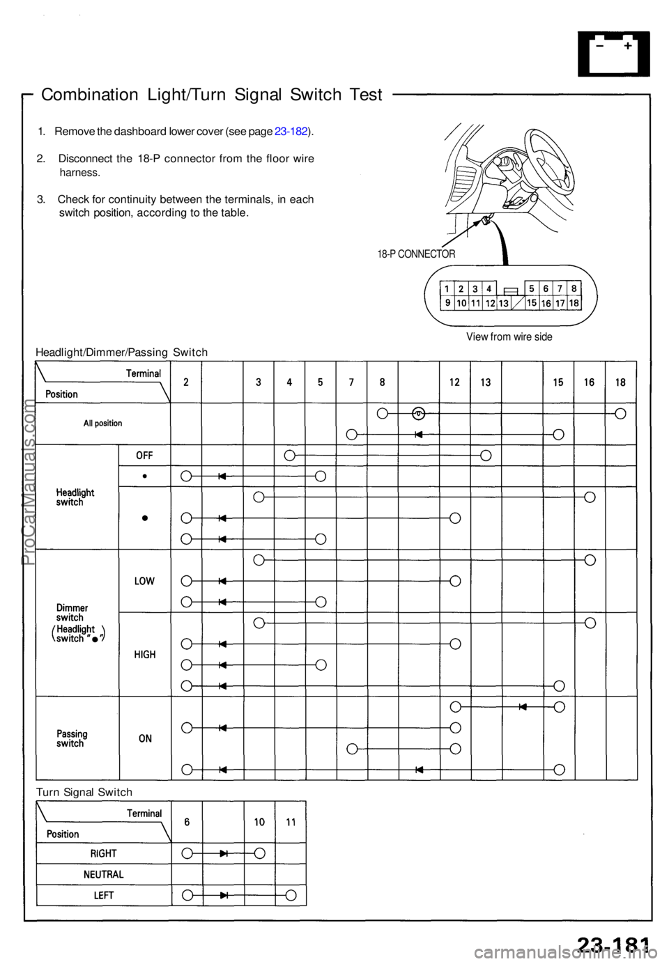
Combination Light/Tur n Signa l Switc h Tes t
1. Remov e th e dashboar d lowe r cove r (se e pag e 23-182 ).
2 . Disconnec t th e 18- P connecto r fro m th e floo r wir e
harness .
3. Chec k fo r continuit y betwee n th e terminals , i n eac h
switc h position , accordin g t o th e table .
18-P CONNECTO R
View fro m wir e sid e
Tur n Signa l Switc h
Headlight/Dimmer/Passin
g Switc h
ProCarManuals.com
Page 832 of 1640
Lighting Syste m
Headlight/Tur n Signa l Switc h Replacemen t
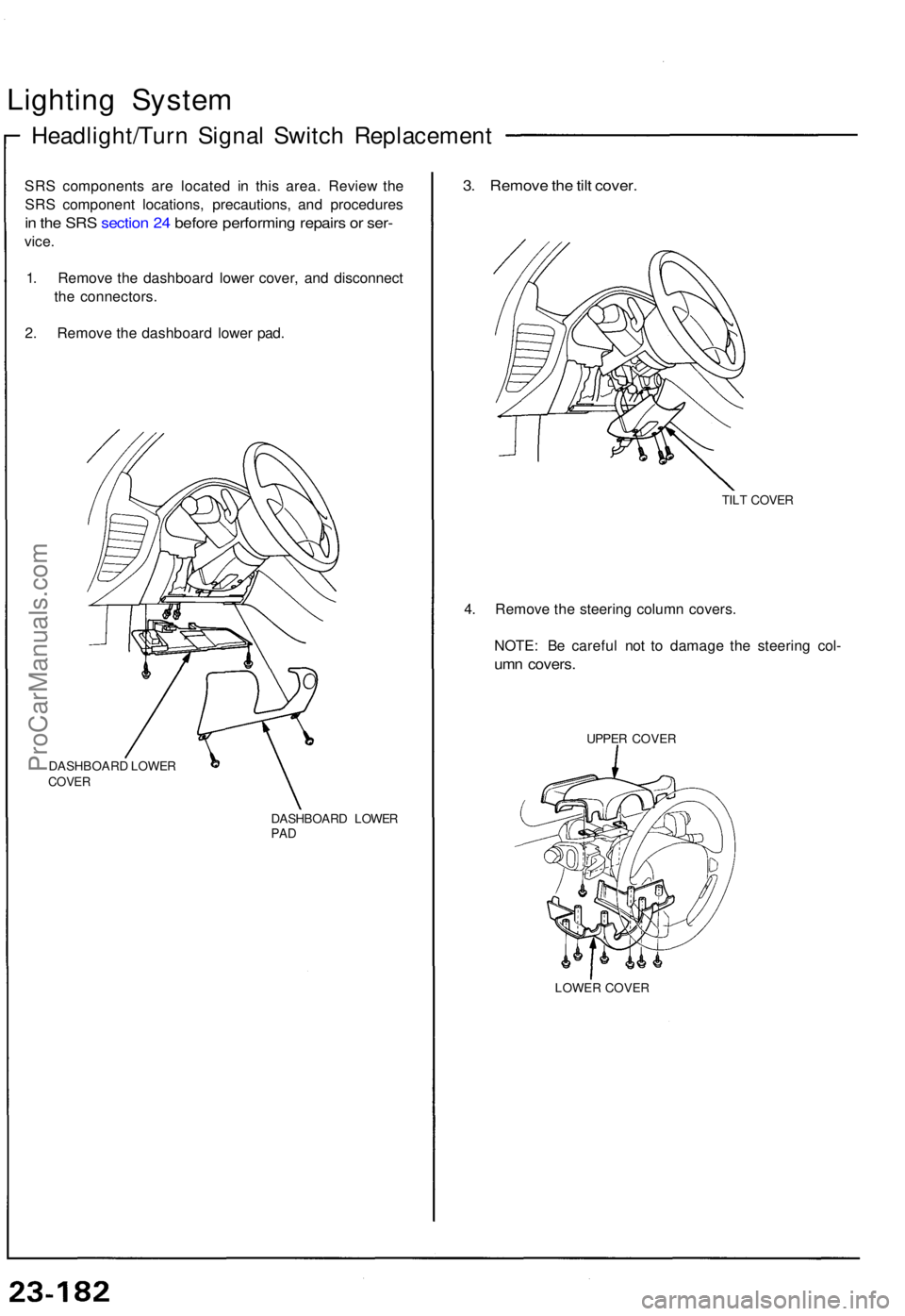
SRS component s ar e locate d i n thi s area . Revie w th e
SR S componen t locations , precautions , an d procedure s
in th e SR S sectio n 24 befor e performin g repair s o r ser -
vice .
1 . Remov e th e dashboar d lowe r cover , an d disconnec t
th e connectors .
2 . Remov e th e dashboar d lowe r pad .
DASHBOAR D LOWE RCOVER
DASHBOAR D LOWE RPAD
3. Remov e th e til t cover .
TILT COVE R
4. Remov e th e steerin g colum n covers .
NOTE : B e carefu l no t t o damag e th e steerin g col -
umn covers .
UPPER COVE R
LOWE R COVE R
ProCarManuals.com
Page 833 of 1640
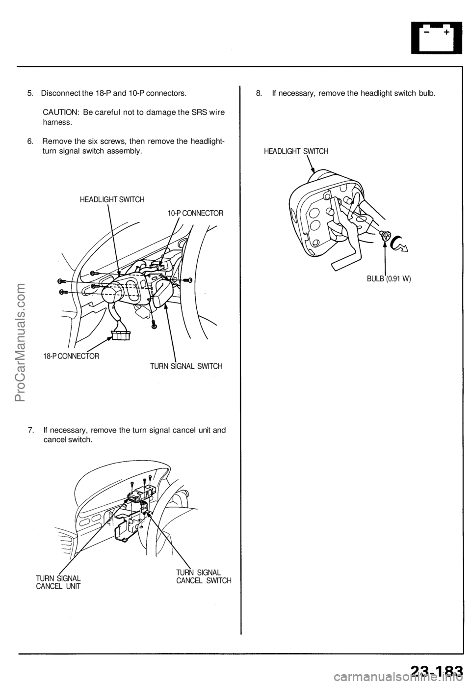
5. Disconnect the 18-P and 10-P connectors.
CAUTION: Be careful not to damage the SRS wire
harness.
6. Remove the six screws, then remove the headlight-
turn signal switch assembly.
HEADLIGHT SWITCH
10-P CONNECTOR
18-P CONNECTOR
TURN SIGNAL SWITCH
7. If necessary, remove the turn signal cancel unit and
cancel switch.
TURN SIGNAL
CANCEL UNIT
TURN SIGNAL
CANCEL SWITCH
8. If necessary, remove the headlight switch bulb.
HEADLIGHT SWITCH
BULB (0.91 W)ProCarManuals.com
Page 834 of 1640
Lighting Syste m
Retracto r Switc h Remova l
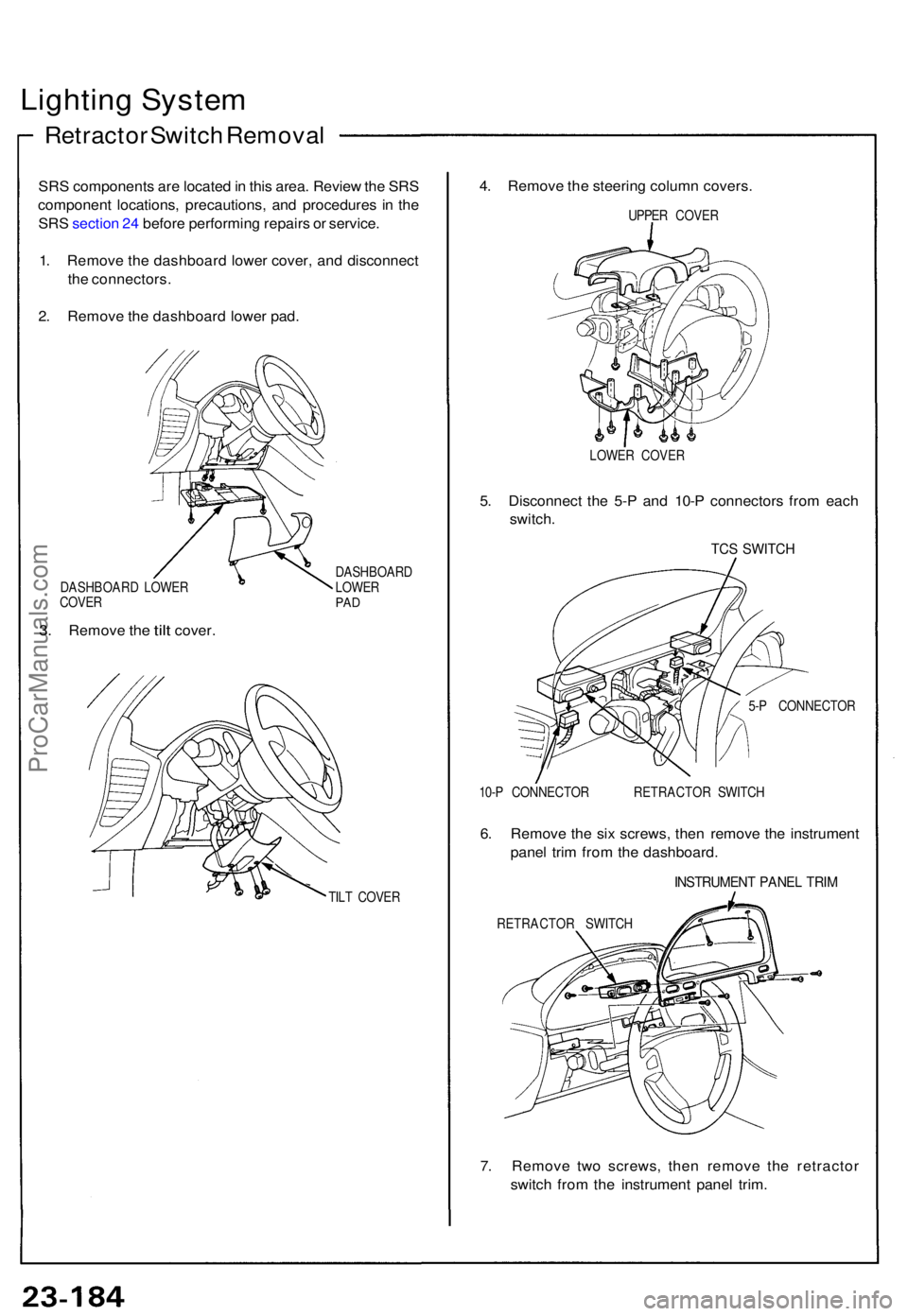
SRS component s ar e locate d in thi s area . Revie w th e SR S
componen t locations , precautions , an d procedure s i n th e
SR S sectio n 24 befor e performin g repair s o r service .
1 . Remov e th e dashboar d lowe r cover , an d disconnec t
th e connectors .
2 . Remov e th e dashboar d lowe r pad .
DASHBOAR D LOWE R
COVE R
3. Remov e the tilt cover .
DASHBOAR D
LOWE R
PAD
TIL T COVE R
4. Remov e th e steerin g colum n covers .
UPPER COVE R
LOWE R COVE R
5. Disconnec t th e 5- P an d 10- P connector s fro m eac h
switch .
TCS SWITC H
5-P CONNECTO R
10- P CONNECTO R RETRACTO R SWITC H
6. Remov e th e si x screws, then remov e th e instrumen t
pane l tri m fro m th e dashboard .
INSTRUMEN T PANE L TRI M
RETRACTO R SWITC H
7. Remov e tw o screws , the n remov e th e retracto r
switc h fro m th e instrumen t pane l trim .
ProCarManuals.com
Page 835 of 1640
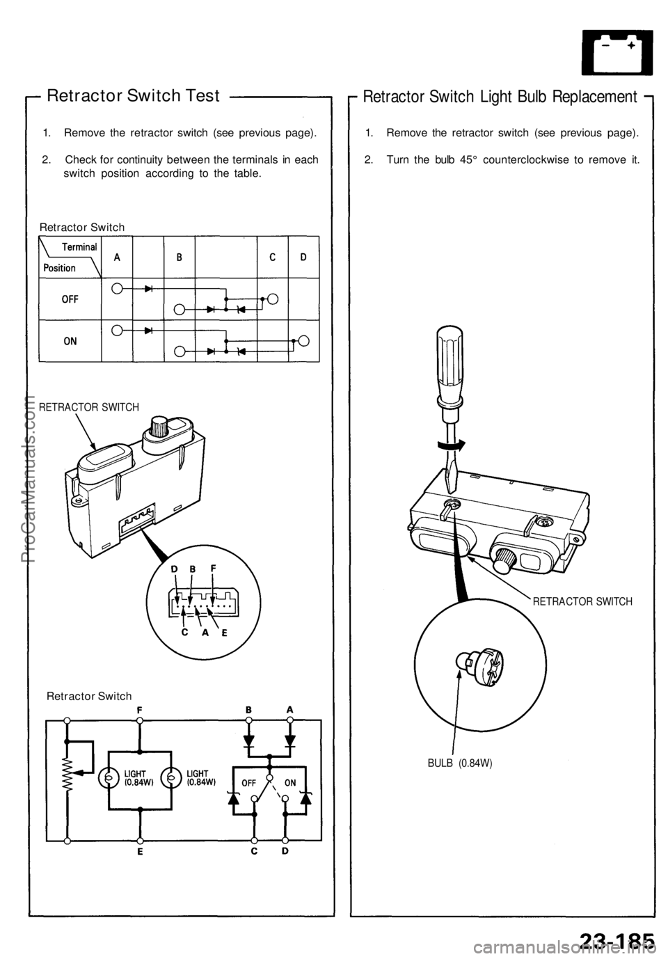
Retractor Switch Test
1. Remove the retractor switch (see previous page).
2. Check for continuity between the terminals in each
switch position according to the table.
Retractor Switch
RETRACTOR SWITCH
Retractor Switch
Retractor Switch Light Bulb Replacement
1. Remove the retractor switch (see previous page).
2. Turn the bulb 45° counterclockwise to remove it.
RETRACTOR SWITCH
BULB (0.84W)ProCarManuals.com
Page 836 of 1640
Lighting System
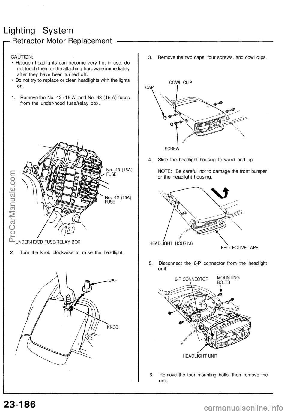
Retractor Motor Replacement
CAUTION:
• Halogen headlights can become very hot in use; do
not touch them or the attaching hardware immediately
after they have been turned off.
• Do not try to replace or clean headlights with the lights
on.
1. Remove the No. 42 (15 A) and No. 43 (15 A) fuses
from the under-hood fuse/relay box.
No. 43
(15A)
FUSE
No. 42
(15A)
FUSE
UNDER-HOOD FUSE/RELAY BOX
2. Turn the knob clockwise to raise the headlight.
CAP
KNOB
3. Remove the two caps, four screws, and cowl clips.
COWL CLIP
CAP
SCREW
4. Slide the headlight housing forward and up.
NOTE: Be careful not to damage the front bumper
or the headlight housing.
HEADLIGHT HOUSING
PROTECTIVE TAPE
5. Disconnect the 6-P connector from the headlight
unit.
6-P CONNECTOR
HEADLIGHT UNIT
6. Remove the four mounting bolts, then remove the
unit.
MOUNTING
BOLTSProCarManuals.com
Page 837 of 1640
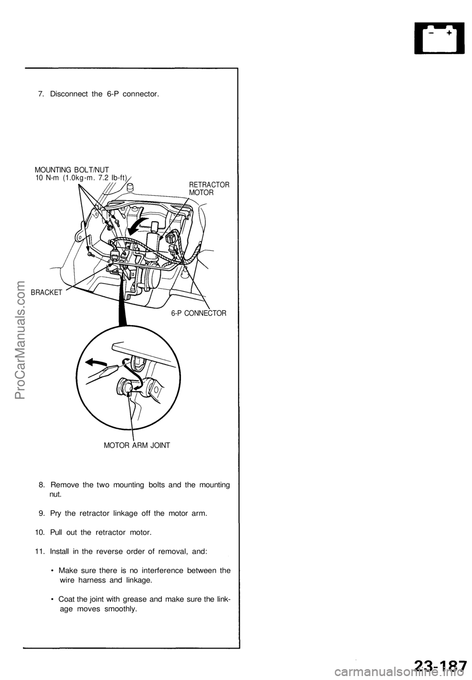
7. Disconnect the 6-P connector.
MOUNTING BOLT/NUT
10 N-m (1.0kg-m. 7.2 Ib-ft)
RETRACTOR
MOTOR
BRACKET
6-P CONNECTOR
MOTOR ARM JOINT
8. Remove the two mounting bolts and the mounting
nut.
9. Pry the retractor linkage off the motor arm.
10. Pull out the retractor motor.
11. Install in the reverse order of removal, and:
• Make sure there is no interference between the
wire harness and linkage.
• Coat the joint with grease and make sure the link-
age moves smoothly.ProCarManuals.com
Page 838 of 1640
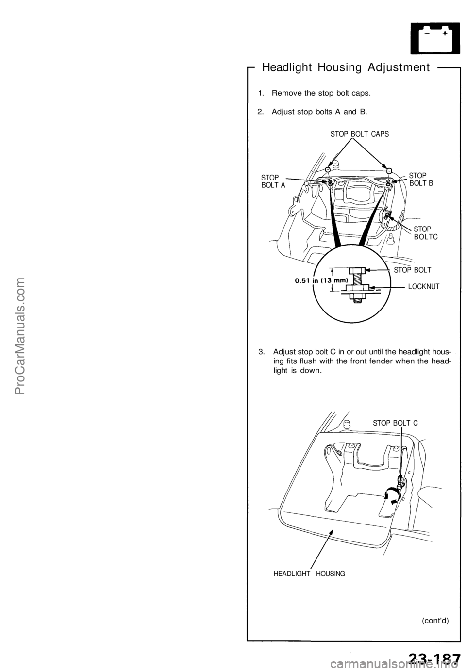
Headlight Housing Adjustment
1. Remove the stop bolt caps.
2. Adjust stop bolts A and B.
STOP BOLT CAPS
STOP
BOLT A
STOP
BOLT B
STOP
BOLTC
STOP BOLT
LOCKNUT
3. Adjust stop bolt C in or out until the headlight hous-
ing fits flush with the front fender when the head-
light is down.
STOP BOLT C
HEADLIGHT HOUSING
(cont'd)ProCarManuals.com
Page 839 of 1640
Lighting System
Headlight Housing Adjustment
(cont'd)
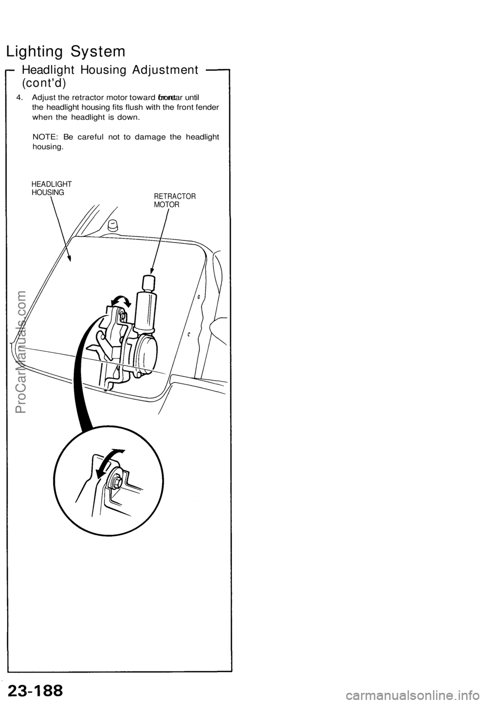
4. Adjust the retractor motor toward
front
or rear until
the headlight housing fits flush with the front fender
when the headlight is down.
NOTE: Be careful not to damage the headlight
housing.
HEADLIGHT
HOUSING
RETRACTOR
MOTORProCarManuals.com
Page 840 of 1640
Lighting Syste m
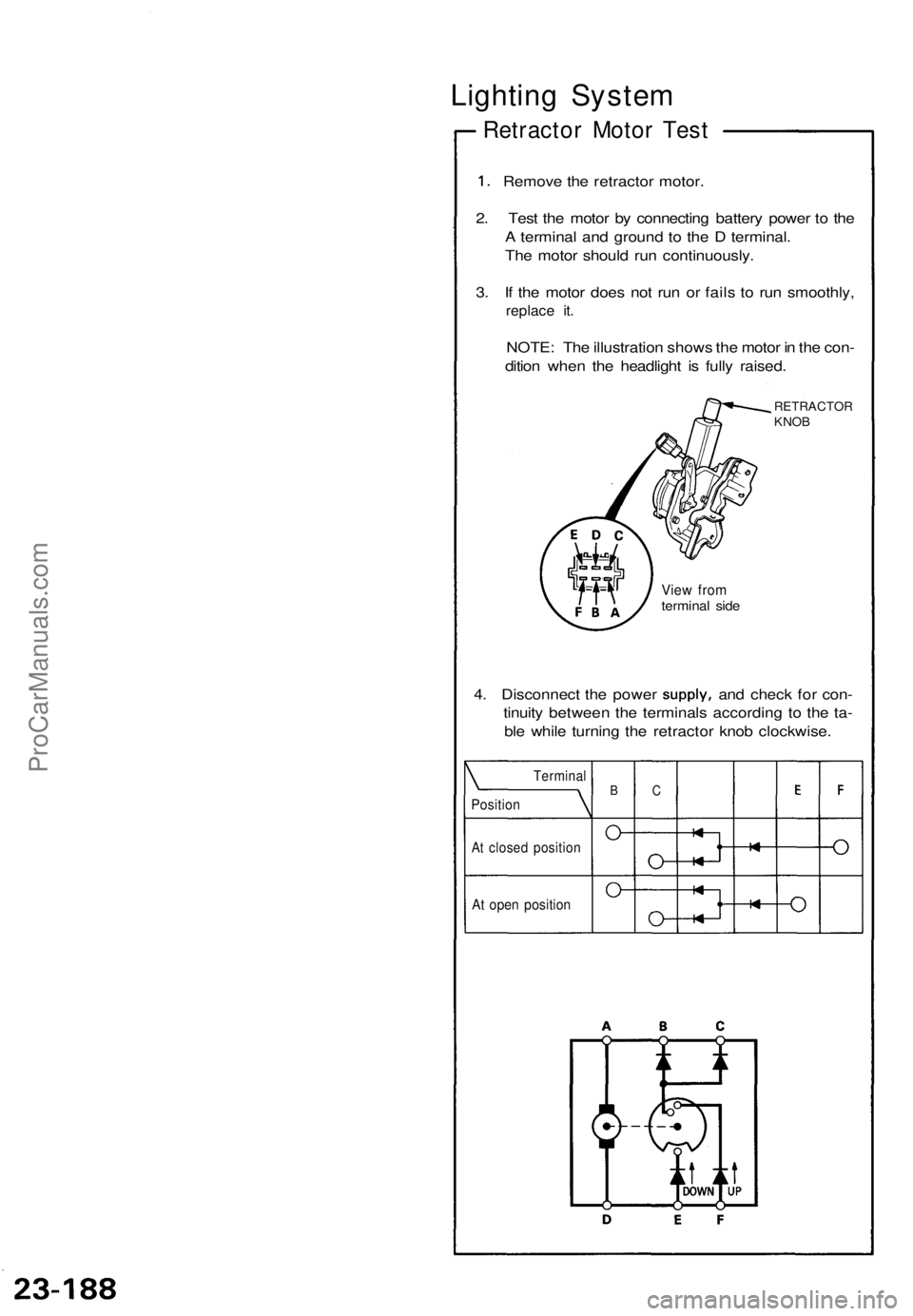
Retracto r Moto r Tes t
1. Remov e th e retracto r motor .
2 . Tes t th e moto r b y connectin g batter y powe r t o th e
A termina l an d groun d t o th e D terminal .
Th e moto r shoul d ru n continuously .
3 . I f th e moto r doe s no t ru n o r fail s t o ru n smoothly ,
replace it .
NOTE : Th e illustratio n show s th e moto r i n th e con -
ditio n whe n th e headligh t i s full y raised .
RETRACTO RKNOB
View fro mtermina l sid e
BCTermina l
Position
At close d positio n
At ope n positio n
4. Disconnec t th e powe r supply , and chec k fo r con -
tinuit y betwee n th e terminal s accordin g t o th e ta -
bl e whil e turnin g th e retracto r kno b clockwise .
ProCarManuals.com
Trending: low oil pressure, battery capacity, parking brake, brake, jump start, high beam, engine coolant
