ACURA NSX 1997 Service Repair Manual
Manufacturer: ACURA, Model Year: 1997,
Model line: NSX,
Model: ACURA NSX 1997
Pages: 1503, PDF Size: 57.08 MB
ACURA NSX 1997 Service Repair Manual
NSX 1997
ACURA
ACURA
https://www.carmanualsonline.info/img/32/56989/w960_56989-0.png
ACURA NSX 1997 Service Repair Manual
Trending: AUX, flat tire, height adjustment, transmission oil, child restraint, airbag off, check oil
Page 1231 of 1503
Troubleshooting
Tips and Precautions
Before Troubleshooting
Check applicable fuses in the appropriate fuse box.
Check the battery for damage, state of charge, and
clean and tight connections.
Check the alternator belt tension.
CAUTION:
Do not quick-charge a battery unless the battery
ground cable has been disconnected.
Otherwise you will damage the alternator
diodes.
Do not attempt to crank the engine with the bat-
tery ground cable loosely connected or you will
severely damage the wiring.
Handling Connectors
Make sure the connectors are clean and have no loose
wire terminals.
Make sure multiple cavity connectors are packed with
grease (except watertight connectors).
All connectors have push-down release type locks.
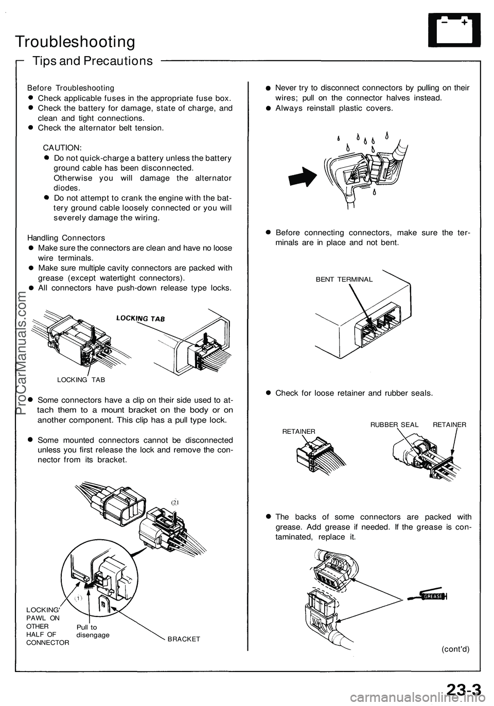
LOCKING TAB
Some connectors have a clip on their side used to at-
tach them to a mount bracket on the body or on
another component. This clip has a pull type lock.
Some mounted connectors cannot be disconnected
unless you first release the lock and remove the con-
nector from its bracket.
(21
LOCKING'
PAWL ON
OTHER
HALF OF
CONNECTOR
Pull to
disengage
BRACKET
Never try to disconnect connectors by pulling on their
wires; pull on the connector halves instead.
Always reinstall plastic covers.
Before connecting connectors, make sure the ter-
minals are in place and not bent.
BENT TERMINAL
Check for loose retainer and rubber seals.
RETAINER
RUBBER SEAL RETAINER
The backs of some connectors are packed with
grease. Add grease if needed. If the grease is con-
taminated, replace it.
(cont'd)ProCarManuals.com
Page 1232 of 1503
Troubleshooting
Tips and Precautions (cont'd)
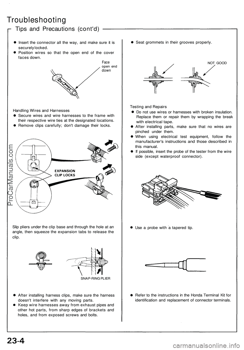
Insert the connector all the way, and make sure it is
securely locked.
Position wires so that the open end of the cover
faces down.
Face
open end
down
Handling Wires and Harnesses
Secure wires and wire harnesses to the frame with
their respective wire ties at the designated locations.
Remove clips carefully; don't damage their locks.
Slip pliers under the clip base and through the hole at an
angle, then squeeze the expansion tabs to release the
clip.
After installing harness clips, make sure the harness
doesn't interfere with any moving parts.
Keep wire harnesses away from exhaust pipes and
other hot parts, from sharp edges of brackets and
holes, and from exposed screws and bolts.
Seat grommets in their grooves properly.
NOT GOOD
Testing and Repairs
Do not use wires or harnesses with broken insulation.
Replace them or repair them by wrapping the break
with electrical tape.
After installing parts, make sure that no wires are
pinched under them.
When using electrical test equipment, follow the
manufacturer's instructions and those described in
this manual.
If possible, insert the probe of the tester from the wire
side (except waterproof connector).
Use a probe with a tapered tip.
Refer to the instructions in the Honda Terminal Kit for
identification and replacement of connector terminals.
SNAP-RING PLIERProCarManuals.com
Page 1233 of 1503
Five-step Troubleshootin g —————
1. Verif y Th e Complain t
Tur n o n al l th e component s i n th e proble m circui t t o
verif y th e custome r complaint . Not e th e symp -
toms . D o no t begi n disassembl y o r testin g unti l yo u
hav e narrowe d dow n th e proble m area .
2 . Analyz e Th e Schemati c
Loo k u p th e schemati c fo r th e proble m circuit .
Determin e ho w th e circui t i s suppose d t o wor k b y
tracin g th e curren t path s fro m th e powe r fee d
throug h th e circui t component s t o ground . I f
severa l circuit s fai l a t th e sam e time , th e fus e o r
groun d i s a likel y cause .
Base d o n th e symptom s an d you r understandin g o f
th e circui t operation , identif y on e o r mor e possibl e
cause s o f th e problem .
3 . Isolat e Th e Proble m B y Testin g Th e Circui t
Mak e circui t test s t o chec k th e diagnosi s yo u mad e
i n ste p 2 . Kee p i n min d tha t a logical , simpl e pro -
cedur e i s th e ke y t o efficien t troubleshooting . Tes t
fo r th e mos t likel y caus e o f failur e first . Tr y t o mak e
test s a t point s tha t ar e easil y accessible . 4
. Fi x Th e Proble m
Onc e th e specifi c proble m is identified , mak e th e
repair . B e sur e t o us e prope r tool s an d saf e
procedures .
5. Mak e Sur e Th e Circui t Work s
Tur n o n al l component s i n th e repaire d circui t i n al l
mode s t o mak e sur e you'v e fixe d th e entir e pro -
blem . I f th e proble m wa s a blow n fuse , b e sur e t o
tes t al l o f th e circuit s o n tha t fuse . Mak e sur e n o
ne w problem s tur n u p an d th e origina l proble m
doe s no t recur .
ProCarManuals.com
Page 1234 of 1503
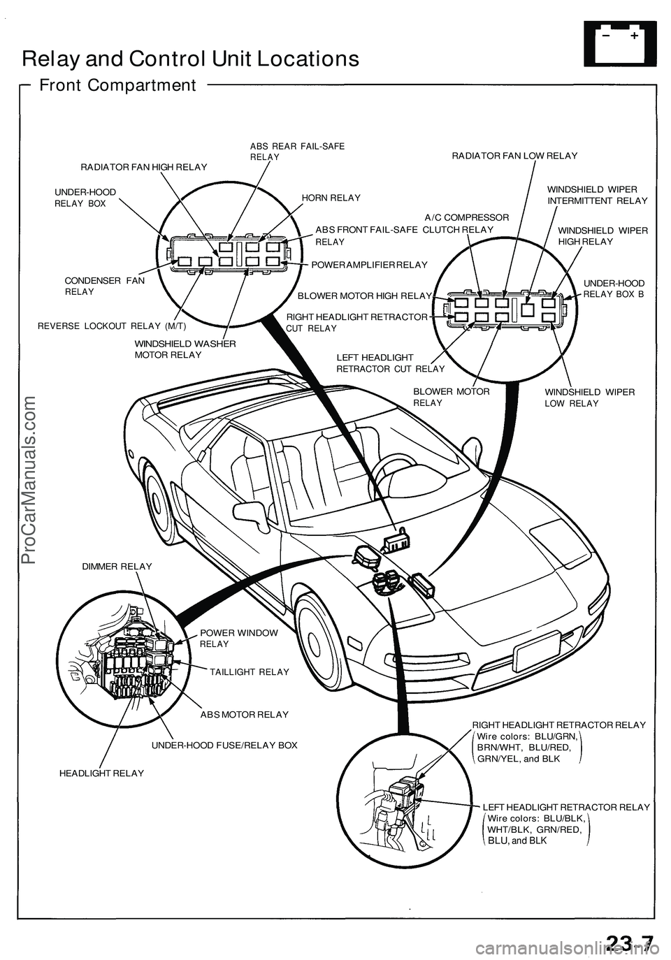
Relay and Control Unit Locations
Front Compartment
ABS REAR FAIL-SAFE
RELAY
RADIATOR FAN LOW RELAY
RADIATOR FAN HIGH RELAY
UNDER-HOOD
RELAY BOX
CONDENSER FAN
RELAY
REVERSE LOCKOUT RELAY (M/T)
WINDSHIELD WIPER
INTERMITTENT RELAY
WINDSHIELD WIPER
HIGH RELAY
UNDER-HOOD
RELAY BOX B
WINDSHIELD WIPER
LOW RELAY
A/C COMPRESSOR
ABS FRONT FAIL-SAFE CLUTCH RELAY
RELAY
POWER AMPLIFIER RELAY
BLOWER MOTOR HIGH RELAY
RIGHT HEADLIGHT RETRACTOR
CUT RELAY
WINDSHIELD WASHER
MOTOR RELAY
LEFT HEADLIGHT
RETRACTOR CUT RELAY
BLOWER MOTOR
RELAY
DIMMER RELAY
POWER WINDOW
RELAY
TAILLIGHT RELAY
ABS MOTOR RELAY
UNDER-HOOD FUSE/RELAY BOX
HEADLIGHT RELAY
HORN RELAY
RIGHT HEADLIGHT RETRACTOR RELAY
Wire colors: BLU/GRN,
BRN/WHT, BLU/RED,
GRN/YEL, and BLK
LEFT HEADLIGHT RETRACTOR RELAY
Wire colors: BLU/BLK,
WHT/BLK, GRN/RED,
BLU,
and BLKProCarManuals.com
Page 1235 of 1503
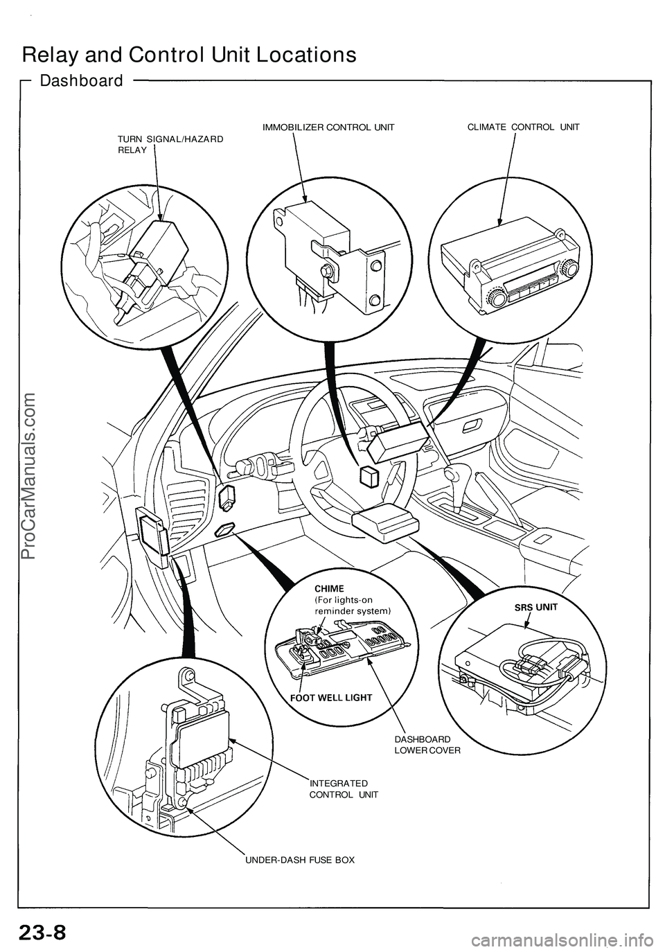
Relay and Control Unit Locations
Dashboard
IMMOBILIZER CONTROL UNIT
CLIMATE CONTROL UNIT
TURN SIGNAL/HAZARD
RELAY
DASHBOARD
LOWER COVER
INTEGRATED
CONTROL UNIT
UNDER-DASH FUSE BOXProCarManuals.com
Page 1236 of 1503
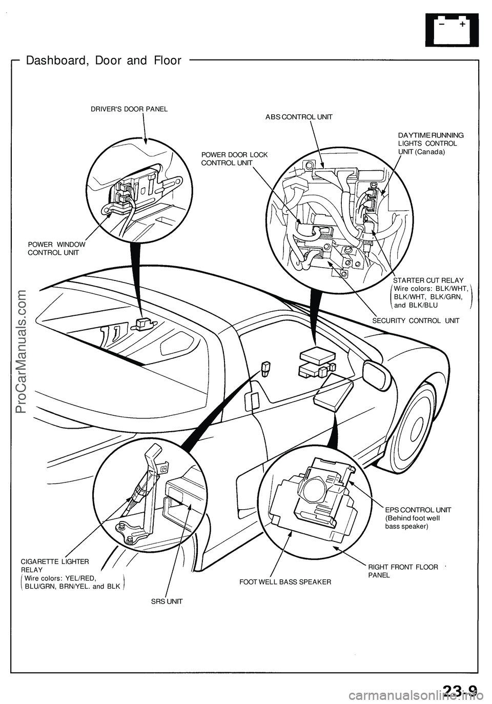
Dashboard, Doo r an d Floo r
DRIVER' S DOO R PANE LABS CONTRO L UNI T
DAYTIM E RUNNIN GLIGHTS CONTRO LUNIT (Canada )
POWER WINDO WCONTRO L UNI T
SECURIT Y CONTRO L UNI T
POWE
R DOO R LOC K
CONTRO L UNI T
CIGARETT E LIGHTE RRELAYWire colors : YEL/RED ,
BLU/GRN , BRN/YEL . an d BL K FOO
T WEL L BAS S SPEAKE R
EPS CONTRO L UNI T(Behin d foo t wel lbass speaker )
RIGH T FRON T FLOO R
PANEL
SRS UNI T
STARTE R CU T RELA Y
Wir e colors : BLK/WHT ,
BLK/WHT , BLK/GRN ,
an d BLK/BL U
ProCarManuals.com
Page 1237 of 1503
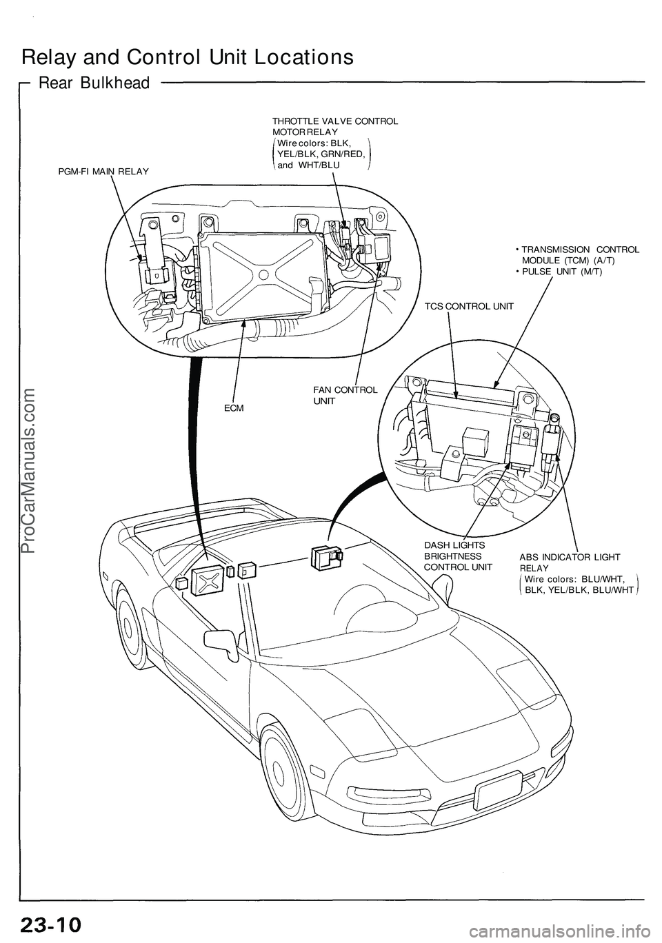
Relay and Control Unit Locations
Rear Bulkhead
PGM-FI MAIN RELAY
THROTTLE VALVE CONTROL
MOTOR RELAY
Wire colors: BLK,
YEL/BLK, GRN/RED,
and WHT/BLU
DASH LIGHTS
BRIGHTNESS
CONTROL UNIT
TRANSMISSION CONTROL
MODULE (TCM) (A/T)
PULSE UNIT (M/T)
ABS INDICATOR LIGHT
RELAY
Wire colors: BLU/WHT,
BLK, YEL/BLK, BLU/WHT
TCS CONTROL UNIT
FAN CONTROL
UNIT
ECMProCarManuals.com
Page 1238 of 1503
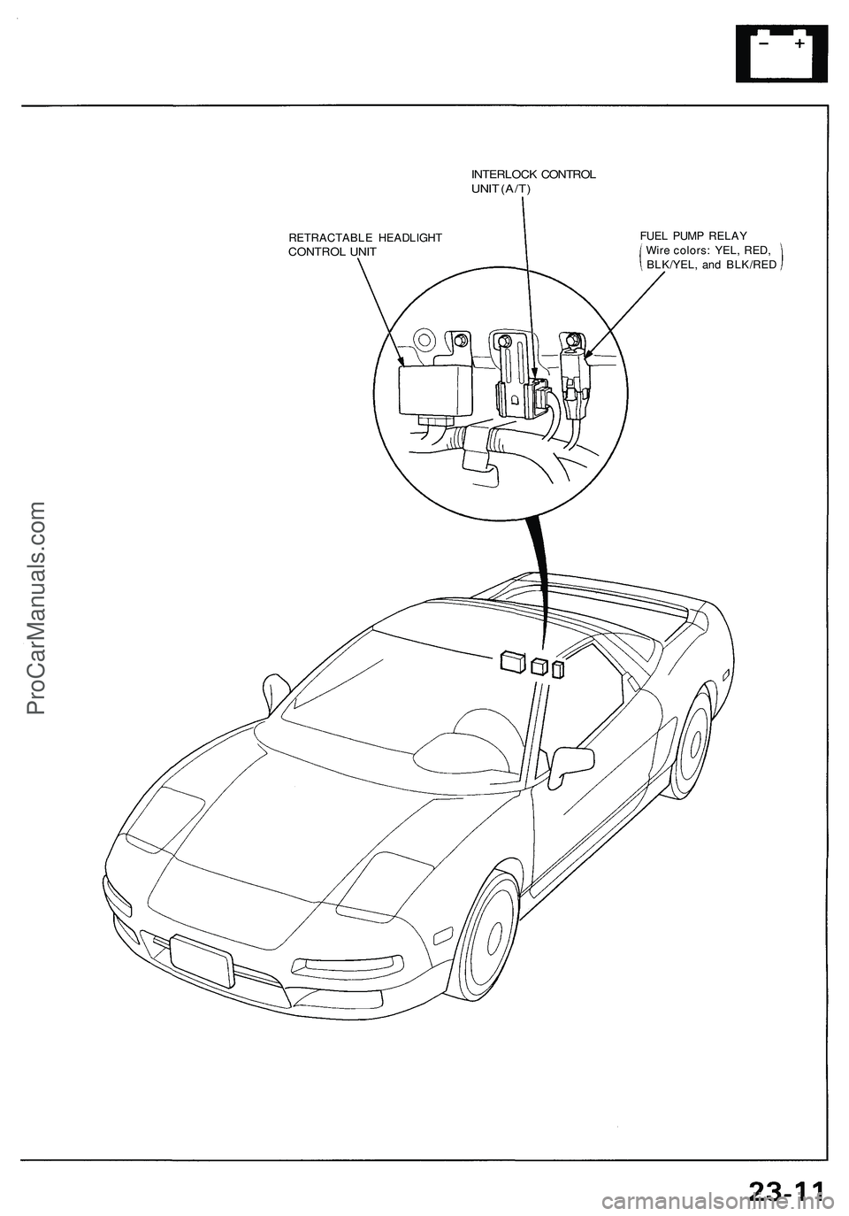
INTERLOCK CONTROL
UNIT (A/T)
RETRACTABLE HEADLIGHT
CONTROL UNIT
FUEL PUMP RELAY
Wire colors: YEL, RED,
BLK/YEL, and BLK/REDProCarManuals.com
Page 1239 of 1503
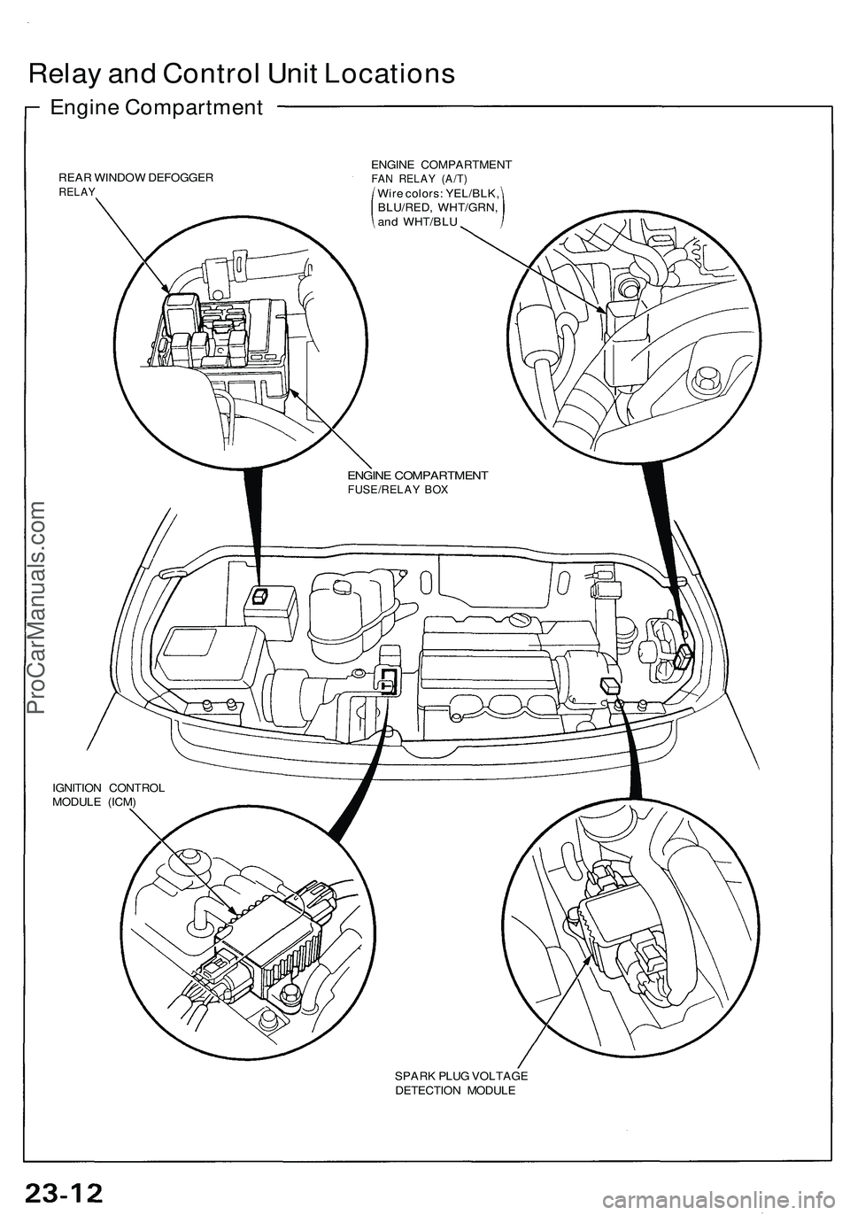
Relay an d Contro l Uni t Location s
Engine Compartmen t
REAR WINDOW DEFOGGE RRELAY
ENGIN E COMPARTMEN TFAN RELA Y (A/T )Wire colors : YEL/BLK ,
BLU/RED , WHT/GRN ,
an d WHT/BL U
ENGINE COMPARTMEN TFUSE/RELAY BO X
IGNITIO N CONTRO L
MODUL E (ICM )
SPARK PLU G VOLTAG E
DETECTIO N MODUL E
ProCarManuals.com
Page 1240 of 1503
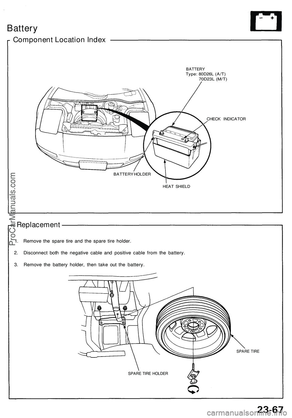
Battery
Component Location Index
BATTERY
Type: 80D26L (A/T)
70D23L (M/T)
CHECK INDICATOR
HEAT SHIELD
Replacement
1. Remove the spare tire and the spare tire holder.
2. Disconnect both the negative cable and positive cable from the battery.
3. Remove the battery holder, then take out the battery.
SPARE TIRE
BATTERY HOLDER
SPARE TIRE HOLDERProCarManuals.com
Trending: gas type, mirror, drain bolt, radio, parking brake, tires, manual radio set


