ACURA NSX 1997 Service Repair Manual
Manufacturer: ACURA, Model Year: 1997, Model line: NSX, Model: ACURA NSX 1997Pages: 1503, PDF Size: 57.08 MB
Page 1211 of 1503

Heater-Evaporator Uni t
Replacemen t
SRS component s ar e locate d in thi s area . Revie w th e SR S
componen t locations , precautions , an d procedure s i n th e
SR S sectio n 24 befor e performin g repair s o r service .
1 . Remov e th e blowe r uni t (se e pag e 22-67 ).
2 . Whe n th e engin e i s cool , drai n th e engin e coolan t
fro m th e radiato r (se e sectio n 10 ).
D o no t remov e th e radiato r ca p whe n
th e engin e i s hot ; th e engin e coolan t i s unde r
pressur e an d coul d severel y scal d you .
CAUTION : Engin e coolan t wil l damag e paint . Quick -
l y rins e an y spille d engin e coolan t of f painte d sur -
faces .
3. Disconnec t th e heater valve cabl e fro m th e heate r
valve .
4 . Disconnec t th e heater hoses. Engin e coolan t wil l
ru n ou t whe n th e hose s ar e disconnected , drai n i t
int o a clea n dri p pan .
HEATE RVALVE CABL E
HEATE R VALV E
5. Recove r th e refrigeran t fro m th e A/ C syste m wit h a
R-134 a refrigeran t Recovery/Recycling/Chargin g
System . (se e pag e 22-73 ).
6 . Disconnec t th e receive r lin e an d th e suctio n lin e fro m
the evaporator . Ca p th e ope n fitting s immediatel y
to kee p moistur e ou t o f th e system .
RECEIVE R LIN E
SECTION LIN E
7. Remov e th e dashboar d (se e sectio n 20 ).
8 . Remov e th e heate r duct .
9 . Remov e th e fou r mountin g bolts , disconnec t th e con -
nector s fro m th e contro l unit s an d th e evaporato r
temperatur e senso r connecto r fro m th e contro l uni t
bracket , the n remov e th e contro l uni t bracket .
CORROSIO N RESISTAN T
B°L T EVAPORATORTEMPERATUR E
SENSO R CONNECTO R
CONTROLUNITBRACKE T
6 x 1. 0 m m9.8 N- m(1.0 kgf-m ,
7. 2 Ibf-ft) '
SRS MAI NHARNES S
6 x 1. 0 m m9.8 N- m (1. 0 kgf-m , 7. 2 Ibf-ft )
10. Remov e th e woofe r enclosur e (se e sectio n 23 ).
ProCarManuals.com
Page 1212 of 1503

11. Disconnec t th e connector s fro m al l th e contro l
motors an d sensor s attache d t o th e heater -
evaporato r unit .
1 2 . Remov e th e tw o mountin g bolt s an d tw o nuts , the n
remov e th e heater-evaporato r uni t throug h th e
passenge r door .
CORROSIO N RESISTAN TBOLTHEATER-EVAPORATO R UNIT
NUT S29 N- m (3. 0 kgf-m ,
2 2 Ibf-ft )
6 x 1. 0 m m9.8 N- m (1. 0 kgf-m , 7. 2 Ibf-ft )
13. Instal l th e heater-evaporato r uni t i n th e revers e
orde r of removal , and :
• I f you'r e installin g a ne w evaporator , ad d
refrigeran t oi l (ND-OI L 8 ) se e pag e 22-69 ).
• Replac e O-ring s wit h ne w one s a t eac h fitting ,
and appl y refrigeran t oi l t o them .
NOTE : B e sur e t o us e th e righ t O-ring s fo r
R-134 a t o avoi d leakage .
14. Fil l th e radiato r an d reservoi r tan k wit h th e prope r
engine coolan t mixture . Blee d th e ai r fro m th e cool -
in g syste m (se e sectio n 10 ).
CAUTION : Follo w th e sequenc e describe d in th e ai r
blee d procedure . I f you don't , yo u ma y leav e ai r i n
th e syste m whic h coul d damag e th e engine .
15. I f necessary , adjus t th e heate r valv e cable :
• Se t th e ai r mi x contro l moto r a t COO L positio n
(se e pag e 22-57 ).
• Connec t th e en d o f th e heate r valv e cabl e t o th e
heate r valv e arm .
• Gentl y slid e th e cabl e oute r housin g bac k fro m
the en d enoug h to tak e u p an y slac k in th e cable ,
but no t enoug h t o mak e th e othe r en d mov e th e
ar m o n th e ai r mi x contro l motor . The n sna p th e
clam p dow n ove r th e cabl e housing .
CLAMP
HEATE R VALV EARM
HEATE R VALV ECABLE
16. Tur n th e blowe r on , an d mak e sur e tha t ther e is n o
air leakage .
1 7 . Charg e th e syste m (se e pag e 22-91 ), an d tes t per -
formanc e (se e pag e 22-70 ).
SR S UNI T
ProCarManuals.com
Page 1213 of 1503

Heater-Evaporator Unit
Overhaul
1. Remove the heater core cover, remove the pipe clamp, then pull out the heater core.
2. Remove the lower half of the housing, then remove the evaporator.
3. Remove the expansion valve if necessary.
HEATER CORE
PIPE CLAMP
AIR MIX DOOR
LOWER HALF
OF THE HOUSING
CAPILLARY TUBE
SUCTION LINE
EVAPORATOR
The expansion valve capillary tube
must be touching the suction line.
4. Assemble the heater-evaporator unit in the reverse order of disassembly. Hold the expansion valve capillary tube
down against the suction line, and wrap it with tape to hold it there.
EXPANSION VALVE
HEATER CORE
COVER
TAPE
Replace
O-RINGS
Replace
SUCTION LINEProCarManuals.com
Page 1214 of 1503
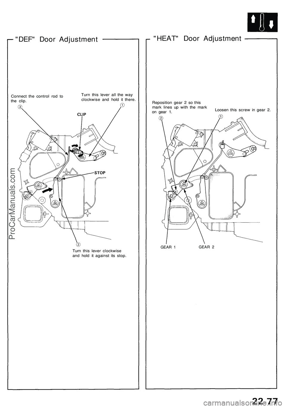
"DEF" Door Adjustment
Connect the control rod to
the clip.
Turn this lever all the way
clockwise and hold it there.
Turn this lever clockwise
and hold it against its stop.
"HEAT" Door Adjustment
Reposition gear 2 so this
mark lines up with the mark
on gear 1.
Loosen this screw in gear 2.
GEAR 1
GEAR 2ProCarManuals.com
Page 1215 of 1503

Condenser
Description
Dual condensers are mounted behind the right and left side of the front bumper as shown. The cooling efficiency of parallel-
dual condensers is as good as or better than a single condenser mounted in front of radiator.
LEFT CONDENSER
RECEIVER/DRYER
RIGHT CONDENSORProCarManuals.com
Page 1216 of 1503
.
3 . Recove r th e refrigeran t usin g a R-134 a refrigeran t
Recover/Recycl")
Replacement
1. Disconnec t th e negativ e cabl e fro m th e battery .
2 . Remov e th e fron t bumpe r (se e sectio n 20 ).
3 . Recove r th e refrigeran t usin g a R-134 a refrigeran t
Recover/Recycling/Chargin g Syste m (se e pag e
22-73 ).
4 . Disconnec t th e discharg e lin e C an d th e condense r
line s fro m th e condenser . Ca p th e ope n fitting s
immediatel y t o kee p moistur e an d dir t ou t o f th e
system .
(Right Condenser )
(Left Condenser )
CONDENSER
LIN E C
CONDENSE R
LIN E A
CONDENSE RLINE A
DISCHARG ELINEC
5. Disconnec t th e connecto r fro m th e condense r fan ,
remov e th e tw o mountin g bolt s an d nut , the n
remov e th e condenser .
CORROSIO N RESISTAN T BOL T
(Righ t Condenser )
RIGHT CONDENSE R
MOUNTING BOLT S6 x 1. 0 m m9.8 N- m (1. 0 kgf-m , 7. 2 Ibf-ft )
(Left Condenser )CONNECTORNUT
LEF T CONDENSE R
MOUNTING BOLT S6 x 1. 0 m m9.8 N- m (1. 0 kgf-m , 7. 2 Ibf-ft )
6. Instal l th e condense r i n th e revers e orde r o f
removal ; and :
• I f you'r e installin g a ne w condenser , ad d
refrigeran t oi l (ND-OI L 8 ) (se e pag e 22-69 ).
• Replac e O-ring s wit h ne w one s a t eac h fitting ,
an d appl y refrigeran t oi l t o them .
NOTE : B e sur e t o us e th e righ t O-ring s fo r
R-134 a t o avoi d leakage .
• Charg e th e syste m (se e pag e 22-91 ), an d tes t it s
performanc e (se e pag e 22-70 ).
NU TCONNECTO R
ProCarManuals.com
Page 1217 of 1503

Condenser
Overhaul
1. Remove the four bolts and nuts. Then separate the condenser duct from the condenser shroud, and remove the
condenser.
2. Remove the three mounting screws, then remove the condenser fan from the condenser shroud.
CONDENSER
CONDENSER
DUCT
NUTS
6 x 1.0 mm
9.8 N-m (1.0 kgf-m, 7.2 Ibf-ft)
CONDENSER FAN
SCREW
CONDENSER
SHROUD
SPACER
3. Assemble the condenser in the reverse order of disassembly. Be careful not to damage the tabs on the condenser
shroud when you attach it to the air intake duct.ProCarManuals.com
Page 1218 of 1503

Compressor
Description
This compresso r i s a DENS O pisto n typ e fo r R-134a . A revolvin g incline d dis c drive s th e surroundin g 1 0 reciprocatin g pis -
tons . A s th e incline d dis c revolved , i t pushe s th e pistons , protecte d b y a cerami c shoe , thu s compressin g th e refrigerant .
RELIEF VALVE
PISTON S
FIEL D COI L
ProCarManuals.com
Page 1219 of 1503
 CENTE
R BOL T
PRESSUR E PLAT EInspection , pag e 22-8 5
SHIM(S )
SNA P RIN G B
Replace .
PU")
Compressor
Illustrated Inde x
RELIE F VALV E
Replacement , pag e 22-8 7
2 5 N- m (2. 6 kgf-m , 1 9 Ibf-ft ) CENTE
R BOL T
PRESSUR E PLAT EInspection , pag e 22-8 5
SHIM(S )
SNA P RIN G B
Replace .
PULLEYInspection , pag e 22-8 5
SNA P RIN G A
Replace .
FIELD COI LInspection , pag e 22-8 5
O-RIN G
Replace .
SUCTIO N SERVIC E VALV E
COMPRESSO R(Do no t disassembly )
ProCarManuals.com
Page 1220 of 1503

Replacement
1. I f th e compresso r stil l works , ru n th e engin e a t idl e
for a fe w minute s wit h th e A/ C on , the n shu t th e
engin e of f an d disconnec t th e negativ e cabl e fro m
the battery .
2. Recove r th e refrigeran t usin g a R-134 a refrigeran t
Recovery/Recycling/Chargin g System . (se e pag e
22-73 ).
3 . Disconnec t th e compresso r connector .
COMPRESSO R
CONNECTO R
4. Rais e th e vehicl e o n a hoist . Mak e sur e it' s properl y
supporte d (se e sectio n 1 ).
5 . Remov e th e fron t bea m (se e sectio n 5 ).
6 . Disconnec t th e suctio n an d discharg e hose s fro m th e
compressor . Ca p th e ope n fitting s immediatel y t o
kee p moistur e an d dir t ou t o f th e system .
DISCHARG E HOS E
SUCTIO N
HOS E
8 x 1.2 5 mm29 N- m(3.0 kgf-m ,
2 2 Ibf-ft )
7. Loose n th e idle r pulle y cente r nu t an d adjustin g bolt ,
the n remov e th e bel t fro m compressor .
ADJUSTING BOL T
IDLE R PULLE Y CENTE R
NUT44 N- m (4. 5 kgf-m ,
3 3 Ibf-ft )
8. Remov e th e fou r mountin g bolt s an d compressor .
COMPRESSO R
MOUNTING BOLT S8 x 1.2 5 mm22 N- m (2. 2 kgf-m ,
1 6 Ibf-ft )
ProCarManuals.com