ACURA NSX 1997 Service Repair Manual
Manufacturer: ACURA, Model Year: 1997, Model line: NSX, Model: ACURA NSX 1997Pages: 1503, PDF Size: 57.08 MB
Page 1191 of 1503
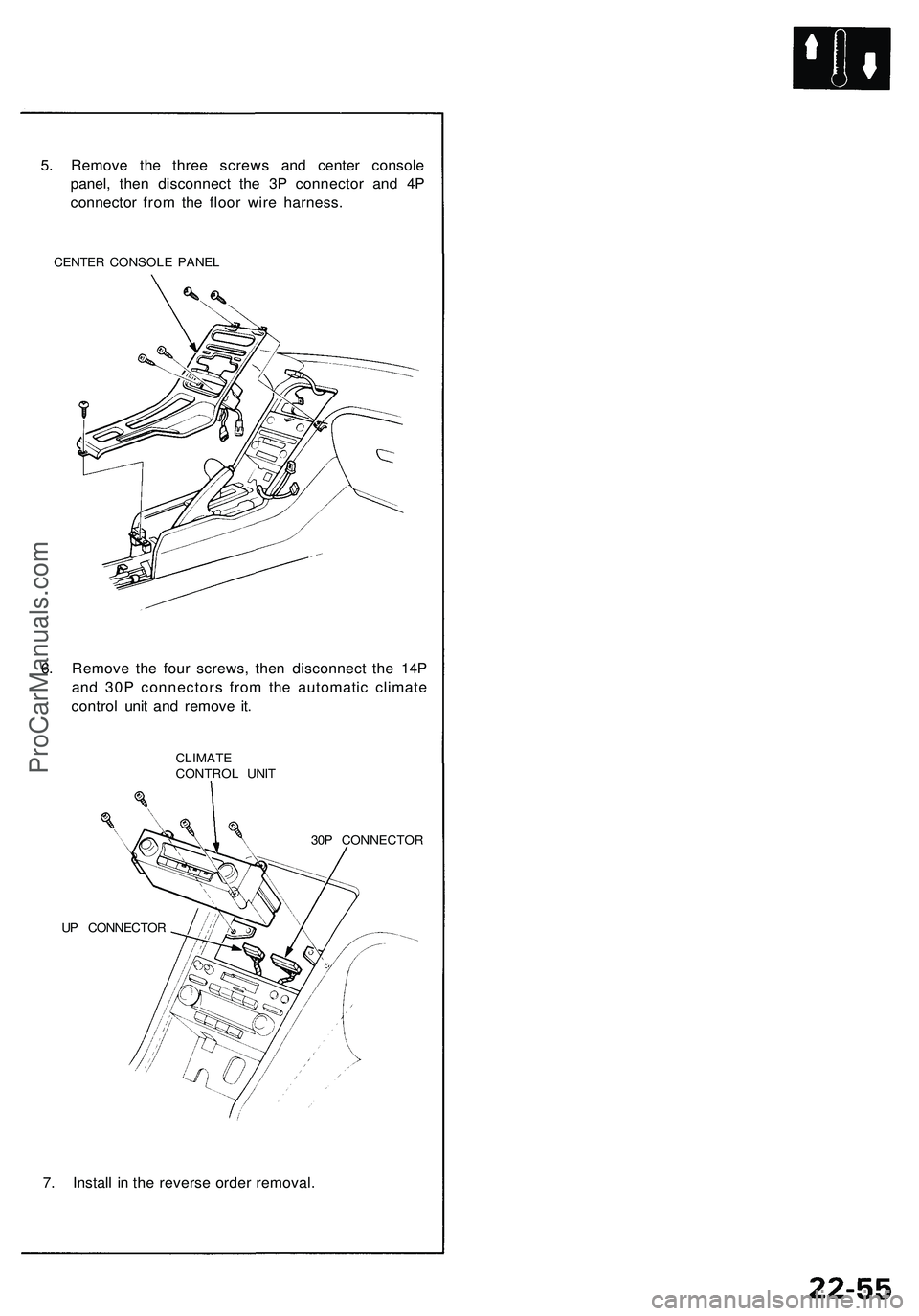
5. Remove the three screws and center console
panel, then disconnect the 3P connector and 4P
connector from the floor wire harness.
CENTER CONSOLE PANEL
6. Remove the four screws, then disconnect the 14P
and 30P connectors from the automatic climate
control unit and remove it.
CLIMATE
CONTROL UNIT
UP CONNECTOR
30P CONNECTOR
7. Install in the reverse order removal.ProCarManuals.com
Page 1192 of 1503
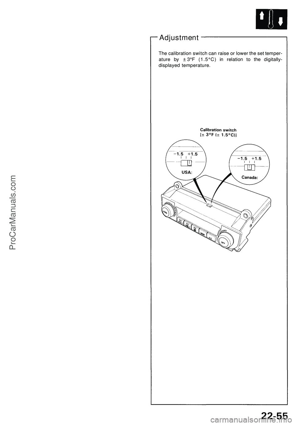
Adjustment
The calibration switch can raise or lower the set temper-
ature by ± 3°F (1.5°C) in relation to the digitally-
displayed temperature.ProCarManuals.com
Page 1193 of 1503
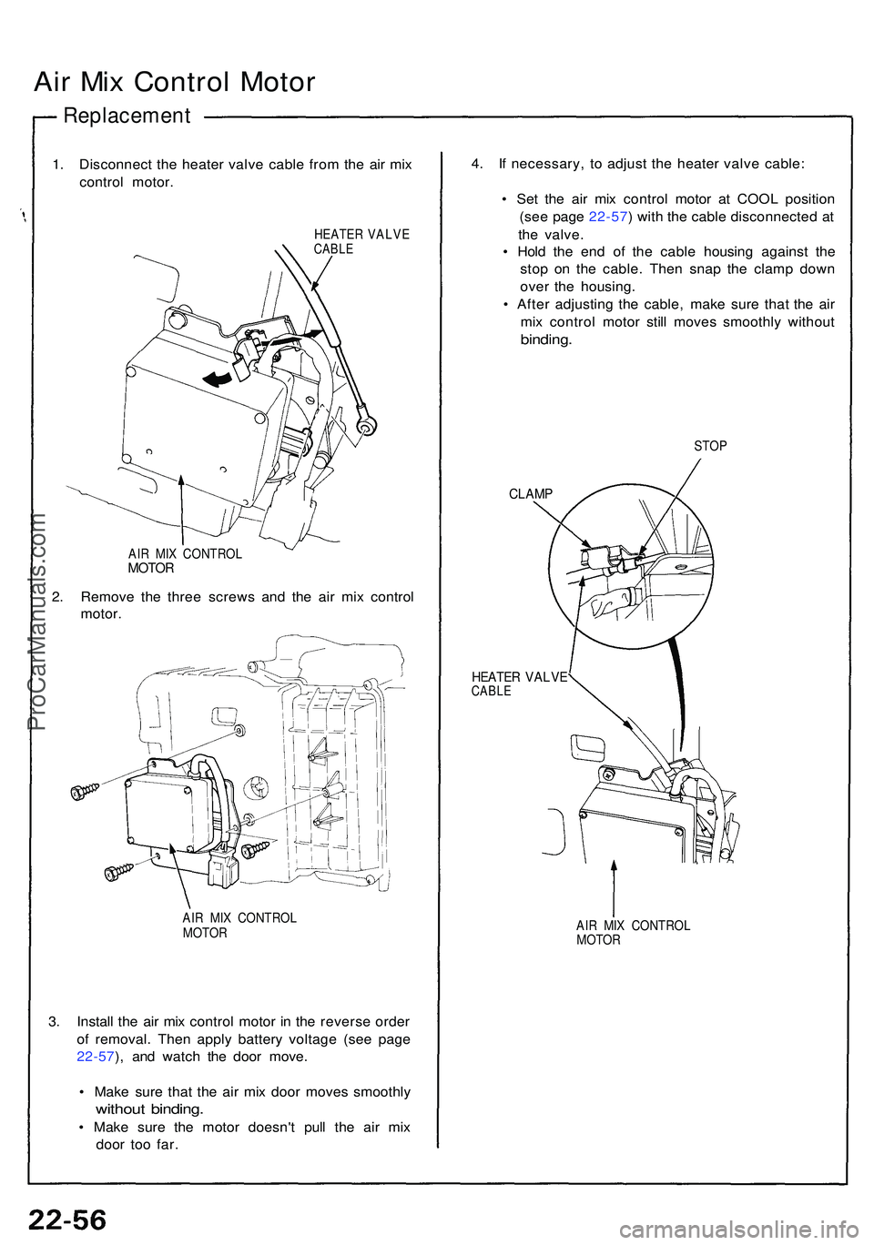
Air Mi x Contro l Moto r
Replacemen t
1. Disconnec t th e heate r valv e cabl e fro m th e ai r mi x
contro l motor .
HEATE R VALV ECABLE
AIR MI X CONTRO LMOTOR
2. Remov e th e thre e screw s an d th e ai r mi x contro l
motor .
AIR MI X CONTRO L
MOTO R
3. Instal l th e ai r mi x contro l moto r i n th e revers e orde r
o f removal . The n appl y batter y voltag e (se e pag e
22-57 ), an d watc h th e doo r move .
• Mak e sur e tha t th e ai r mi x doo r move s smoothl y
without binding .
• Mak e sur e th e moto r doesn' t pul l th e ai r mi x
doo r to o far . 4
. I f necessary , t o adjus t th e heate r valv e cable :
• Se t th e ai r mi x contro l moto r a t COO L positio n
(se e pag e 22-57 ) wit h th e cabl e disconnecte d a t
th e valve .
• Hol d th e en d o f th e cabl e housin g agains t th e
sto p o n th e cable . The n sna p th e clam p dow n
ove r th e housing .
• Afte r adjustin g th e cable , mak e sur e tha t th e ai r
mi x contro l moto r stil l move s smoothl y withou t
binding.
STOP
CLAM P
HEATE R VALV ECABLE
AIR MI X CONTRO L
MOTO R
ProCarManuals.com
Page 1194 of 1503
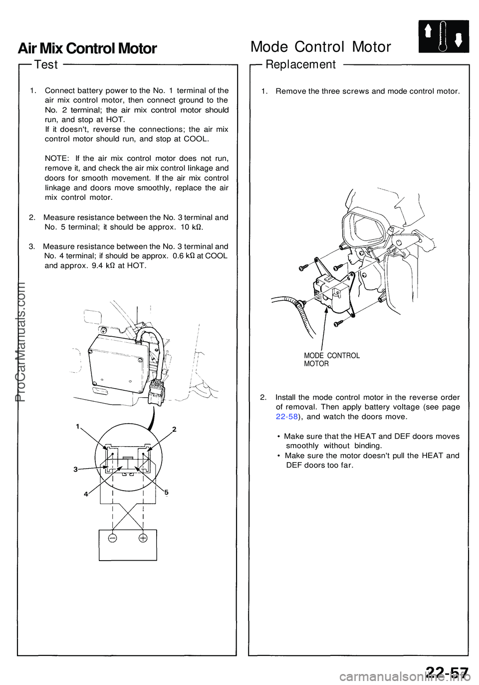
Test
1. Connec t batter y powe r t o th e No . 1 termina l o f th e
ai r mi x contro l motor , the n connec t groun d t o th e
No. 2 terminal ; th e ai r mi x contro l moto r shoul d
run, an d sto p a t HOT .
I f i t doesn't , revers e th e connections ; th e ai r mi x
contro l moto r shoul d run , an d sto p a t COOL .
NOTE : I f th e ai r mi x contro l moto r doe s no t run ,
remov e it , an d chec k th e ai r mi x contro l linkag e an d
door s fo r smoot h movement . I f th e ai r mi x contro l
linkag e an d door s mov e smoothly , replac e th e ai r
mi x contro l motor .
2 . Measur e resistanc e betwee n th e No . 3 termina l an d
No. 5 terminal ; i t shoul d b e approx . 1 0
3 . Measur e resistanc e betwee n th e No . 3 termina l an d
No. 4 terminal ; i f shoul d b e approx . 0. 6 a t COO L
and approx . 9. 4 a t HOT .
Mode Contro l Moto r
Replacemen t
1. Remov e th e thre e screw s an d mod e contro l motor .
MODE CONTRO L
MOTO R
2. Instal l th e mod e contro l moto r i n th e revers e orde r
of removal . The n appl y batter y voltag e (se e pag e
22-58 ), an d watc h th e door s move .
• Mak e sur e tha t th e HEA T an d DE F door s move s
smoothl y withou t binding .
• Mak e sur e th e moto r doesn' t pul l th e HEA T an d
DE F door s to o far .
Air Mix Control Motor
ProCarManuals.com
Page 1195 of 1503
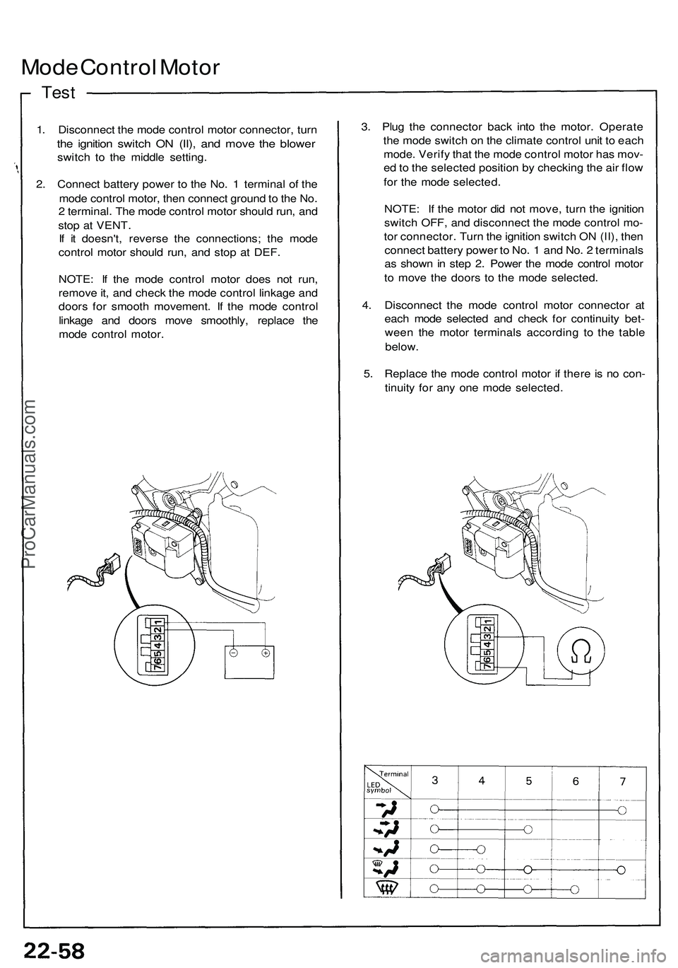
Mode Control Motor
Test
1. Disconnect the mode control motor connector, turn
the ignition switch ON (II), and move the blower
switch to the middle setting.
2. Connect battery power to the No. 1 terminal of the
mode control motor, then connect ground to the No.
2 terminal. The mode control motor should run, and
stop at VENT.
If it doesn't, reverse the connections; the mode
control motor should run, and stop at DEF.
NOTE: If the mode control motor does not run,
remove it, and check the mode control linkage and
doors for smooth movement. If the mode control
linkage and doors move smoothly, replace the
mode control motor.
3. Plug the connector back into the motor. Operate
the mode switch on the climate control unit to each
mode. Verify that the mode control motor has mov-
ed to the selected position by checking the air flow
for the mode selected.
NOTE: If the motor did not move, turn the ignition
switch OFF, and disconnect the mode control mo-
tor connector. Turn the ignition switch ON (II), then
connect battery power to No. 1 and No. 2 terminals
as shown in step 2. Power the mode control motor
to move the doors to the mode selected.
4. Disconnect the mode control motor connector at
each mode selected and check for continuity bet-
ween the motor terminals according to the table
below.
5. Replace the mode control motor if there is no con-
tinuity for any one mode selected.ProCarManuals.com
Page 1196 of 1503
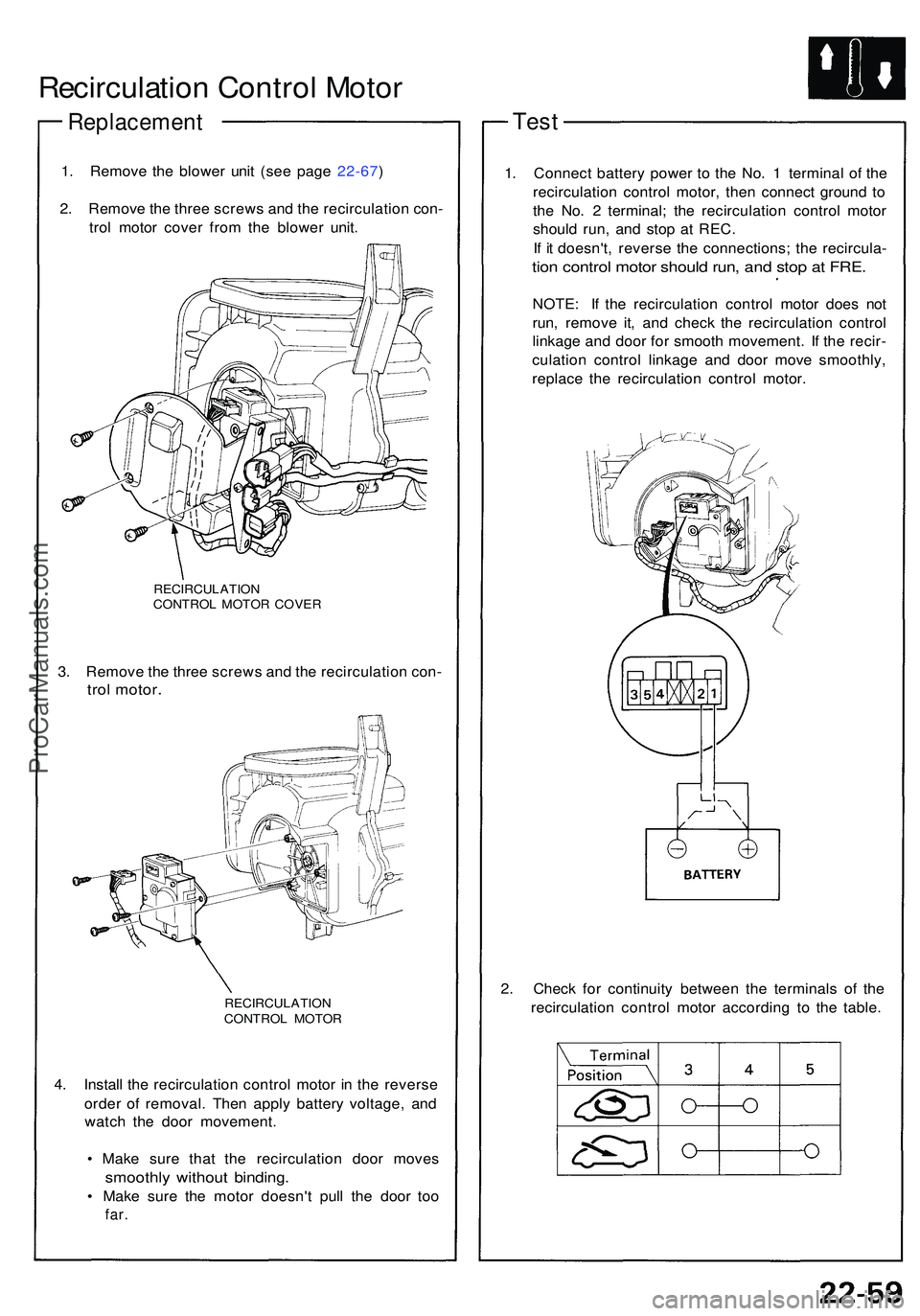
Recirculation Contro l Moto r
Replacemen t
1. Remov e th e blowe r uni t (se e pag e 22-67 )
2 . Remov e th e thre e screw s an d th e recirculatio n con -
tro l moto r cove r fro m th e blowe r unit .
RECIRCULATIO NCONTROL MOTO R COVE R
3. Remov e th e thre e screw s an d th e recirculatio n con -
trol motor .
RECIRCULATIO NCONTROL MOTO R
4. Instal l th e recirculatio n contro l moto r i n th e revers e
orde r o f removal . The n appl y batter y voltage , an d
watc h th e doo r movement .
• Mak e sur e tha t th e recirculatio n doo r move s
smoothl y withou t binding .
• Mak e sur e th e moto r doesn' t pul l th e doo r to o
far .
Tes t
1. Connec t batter y powe r t o th e No . 1 termina l of the
recirculatio n contro l motor , the n connec t groun d t o
th e No . 2 terminal ; th e recirculatio n contro l moto r
shoul d run , an d sto p a t REC .
I f i t doesn't , revers e th e connections ; th e recircula -
tion contro l moto r shoul d run , an d sto p a t FRE .
NOTE : I f th e recirculatio n contro l moto r doe s no t
run , remov e it , an d chec k th e recirculatio n contro l
linkag e an d doo r fo r smoot h movement . I f th e recir -
culatio n contro l linkag e an d doo r mov e smoothly ,
replac e th e recirculatio n contro l motor .
2 . Chec k fo r continuit y betwee n th e terminal s o f th e
recirculatio n contro l moto r accordin g t o th e table .
ProCarManuals.com
Page 1197 of 1503
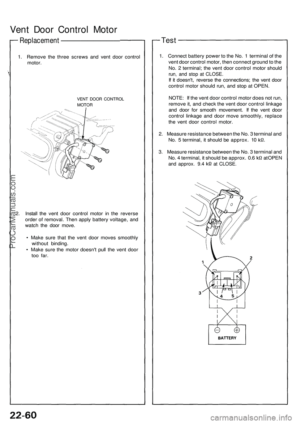
Vent Door Control Motor
Replacement —————————
1. Remove the three screws and vent door control
motor.
VENT DOOR CONTROL
MOTOR
2. Install the vent door control motor in the reverse
order of removal. Then apply battery voltage, and
watch the door move.
• Make sure that the vent door moves smoothly
without binding.
• Make sure the motor doesn't pull the vent door
too
far.
Test
1. Connect battery power to the No. 1 terminal of the
vent door control motor, then connect ground to the
No. 2 terminal; the vent door control motor should
run, and stop at CLOSE.
If it doesn't, reverse the connections; the vent door
control motor should run, and stop at OPEN.
NOTE: If the vent door control motor does not run,
remove it, and check the vent door control linkage
and door for smooth movement. If the vent door
control linkage and door move smoothly, replace
the vent door control motor.
2. Measure resistance between the No. 3 terminal and
No. 5 terminal, it should be approx. 10
3. Measure resistance between the No. 3 terminal and
No. 4 terminal, it should be approx. 0.6 at OPEN
and approx. 9.4 at CLOSE.ProCarManuals.com
Page 1198 of 1503

In-car Temperatur e Senso r
Remova l
The in-ca r temperatur e senso r assembl y include s a
smal l fa n (aspirato r fan ) t o dra w ai r pas t th e senso r (se e
pag e 22-66 ).
SR S component s ar e locate d in thi s area . Revie w th e SR S
componen t locations , precautions , an d procedure s in th e
SR S sectio n 24 befor e performin g repair s o r service .
1 . Remov e th e cente r consol e pane l (se e pag e 22-54 ).
2 . Remov e th e tw o screw s an d th e in-ca r temperatur e
senso r fro m th e unde r sid e o f th e cente r consol e
panel . B e carefu l no t t o damag e th e cente r consol e
panel.
IN-CA R TEMPERATUR ESENSOR
UNDER SID E O F CENTE R
CONSOL E PANE L
Test
Compar e th e resistanc e readin g betwee n th e No . 1 an d
No. 2 terminal s o f th e in-ca r temperatur e senso r wit h
specification s show n i n th e followin g graph : I t shoul d
be withi n specification .
CAUTION: Th e senso r use s a thermisto r whic h ca n
b e damage d if hig h curren t i s applie d to it durin g test -
ing . Therefore , us e a circui t teste r tha t put s ou t a
measurin g curren t o f 1 m A o r less .
ProCarManuals.com
Page 1199 of 1503
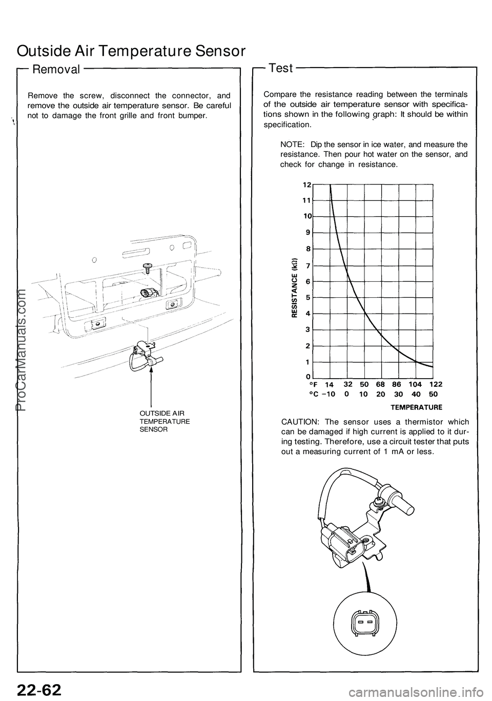
Outside Air Temperature Sensor
Removal
Remove the screw, disconnect the connector, and
remove the outside air temperature sensor. Be careful
not to damage the front grille and front bumper.
OUTSIDE AIR
TEMPERATURE
SENSOR
Test
Compare the resistance reading between the terminals
of the outside air temperature sensor with specifica-
tions shown in the following graph: It should be within
specification.
NOTE: Dip the sensor in ice water, and measure the
resistance. Then pour hot water on the sensor, and
check for change in resistance.
CAUTION: The sensor uses a thermistor which
can be damaged if high current is applied to it dur-
ing testing. Therefore, use a circuit tester that puts
out a measuring current of 1 mA or less.ProCarManuals.com
Page 1200 of 1503
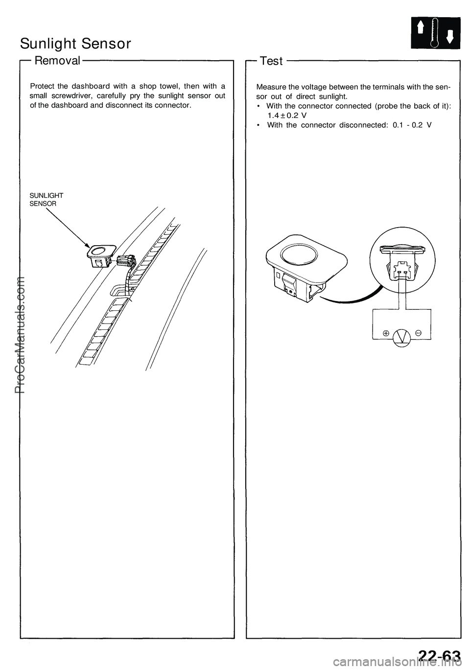
Sunlight Sensor
Removal
Protect the dashboard with a shop towel, then with a
small screwdriver, carefully pry the sunlight sensor out
of the dashboard and disconnect its connector.
SUNLIGHT
SENSOR
Test
Measure the voltage between the terminals with the sen-
sor out of direct sunlight.
• With the connector connected (probe the back of it):
1.4 ± 0.2 V
• With the connector disconnected: 0.1 - 0.2 VProCarManuals.com