ACURA NSX 1997 Service Repair Manual
Manufacturer: ACURA, Model Year: 1997, Model line: NSX, Model: ACURA NSX 1997Pages: 1503, PDF Size: 57.08 MB
Page 1241 of 1503
Battery
Test
Batter y flui d (electrolyte ) contain s sulfuri c acid . I t ma y caus e sever e burn s i f i t get s o n you r ski n o r i n you r eyes .
Wea r protectiv e clothin g an d a fac e shield .
— If electrolyt e get s o n you r ski n o r clothes , rins e i t of f wit h wate r immediately .
— If electrolyt e get s in you r eyes , flus h it ou t b y splashin g wate r i n you r eye s fo r a t leas t 1 5 minutes ; cal l a physicia n
immediately .
A batter y give s of f hydroge n gas. If ignited , th e hydroge n wil l explod e an d coul d crac k th e batter y cas e an d splatte r
aci d o n you . Kee p sparks , flames , an d cigarette s awa y fro m th e battery .
Overchargin g wil l rais e th e temperatur e o f th e electrolyte . Thi s ma y forc e electrolyt e t o spra y ou t o f th e batter y vents .
Follo w th e charge r manufacturer' s instruction s an d charg e th e batter y a t a prope r rate .
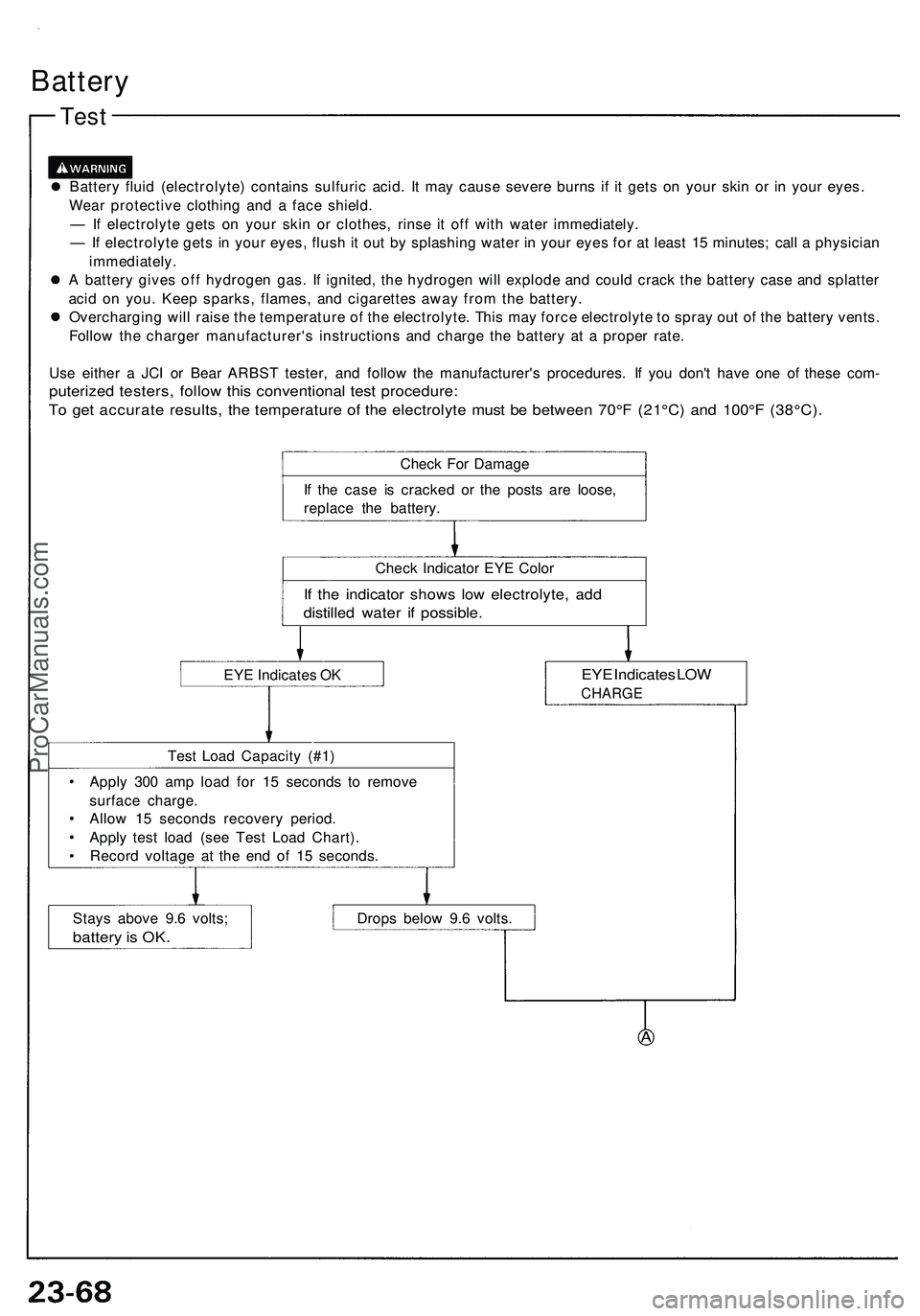
Us e eithe r a JC I o r Bea r ARBS T tester , an d follo w th e manufacturer' s procedures . I f yo u don' t hav e on e of thes e com -
puterize d testers , follo w thi s conventiona l tes t procedure :
To ge t accurat e results , th e temperatur e o f th e electrolyt e mus t b e betwee n 70° F (2 1°C ) an d 100° F (38°C) .
Check Fo r Damag e
I f th e cas e i s cracke d o r th e post s ar e loose ,
replac e th e battery .
Chec k Indicato r EY E Colo r
If th e indicato r show s low electrolyte , ad d
distille d wate r i f possible .
EYE Indicate s O KEY E Indicate s LO W
CHARG E
Test Loa d Capacit y (#1 )
Appl y 30 0 am p loa d fo r 1 5 second s t o remov e
surfac e charge .
Allo w 1 5 second s recover y period .
Appl y tes t loa d (se e Tes t Loa d Chart) .
Recor d voltag e a t th e en d o f 1 5 seconds .
Stay s abov e 9. 6 volts ;
batter y is OK .
Drop s belo w 9. 6 volts .
ProCarManuals.com
Page 1242 of 1503
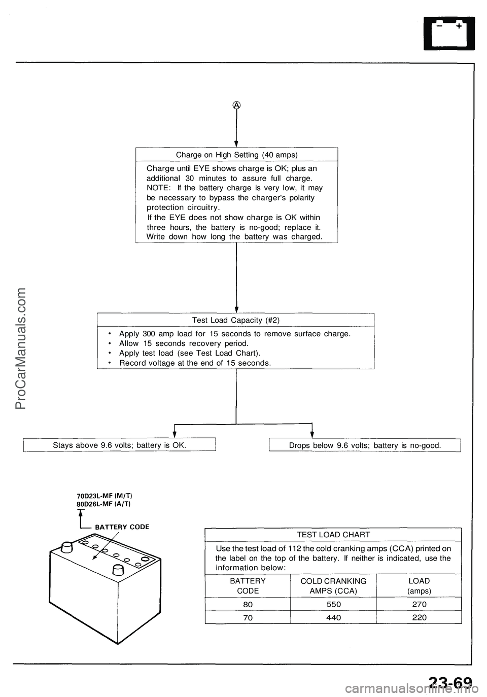
Charge o n Hig h Settin g (4 0 amps )
Charge unti l EY E show s charg e is OK ; plu s a n
additiona l 3 0 minute s t o assur e ful l charge .
NOTE : I f th e batter y charg e i s ver y low , i t ma y
b e necessar y t o bypas s th e charger' s polarit y
protectio n circuitry .
If th e EY E doe s no t sho w charg e i s O K withi n
three hours , th e batter y i s no-good ; replac e it .
Writ e dow n ho w lon g th e batter y wa s charged .
Tes t Loa d Capacit y (#2 )
Appl y 30 0 am p loa d fo r 1 5 second s t o remov e surfac e charge .
Allo w 1 5 second s recover y period .
Appl y tes t loa d (se e Tes t Loa d Chart) .
Recor d voltag e a t th e en d o f 1 5 seconds .
Stay s abov e 9. 6 volts ; batter y i s OK .
Drops belo w 9. 6 volts ; batter y i s no-good .
Use th e tes t loa d o f 11 2 th e col d crankin g amp s (CCA ) printe d o n
th e labe l o n th e to p o f th e battery . I f neithe r i s indicated , us e th e
informatio n below :
TEST LOA D CHAR T
BATTER Y
CODE
80
7 0
COL D CRANKIN G
AMP S (CCA )
550
440
LOA D
(amps )
270
220
ProCarManuals.com
Page 1243 of 1503
Under-dash Fus e Bo x
Removal/Installatio n
SRS component s ar e locate d in thi s area . Revie w th e SR S
componen t locations , precautions , an d procedure s in th e
SR S ( sectio n 24 ) befor e performin g repair s o r service .
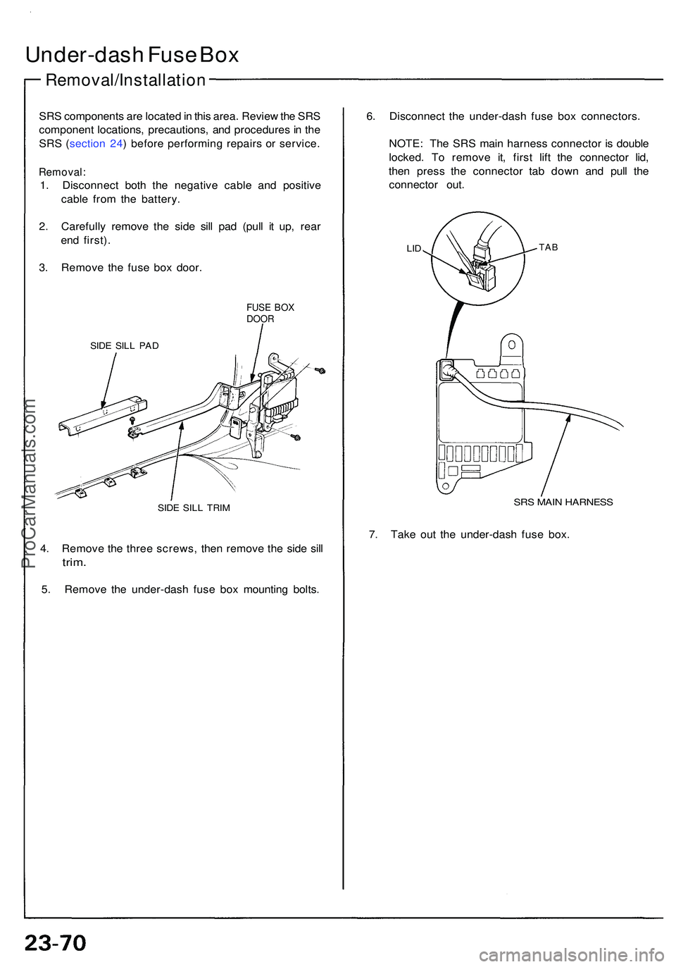
Removal :
1. Disconnec t bot h th e negativ e cabl e an d positiv e
cabl e fro m th e battery .
2 . Carefull y remov e th e sid e sil l pa d (pul l i t up , rea r
en d first) .
3 . Remov e th e fus e bo x door .
FUSE BO XDOO R
SIDE SIL L PA D
SIDE SIL L TRI M
4. Remov e th e thre e screws , the n remov e th e sid e sil l
trim .
5. Remov e th e under-das h fus e bo x mountin g bolts . 6
. Disconnec t th e under-das h fus e bo x connectors .
NOTE : Th e SR S mai n harnes s connecto r i s doubl e
locked . T o remov e it , firs t lif t th e connecto r lid ,
the n pres s th e connecto r ta b dow n an d pul l th e
connecto r out .
LIDTA B
SRS MAI N HARNES S
7. Tak e ou t th e under-das h fus e box .
ProCarManuals.com
Page 1244 of 1503
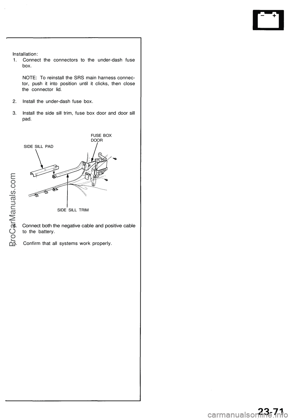
Installation:
1. Connect the connectors to the under-dash fuse
box.
NOTE: To reinstall the SRS main harness connec-
tor, push it into position until it clicks, then close
the connector lid.
2. Install the under-dash fuse box.
3. Install the side sill trim, fuse box door and door sill
pad.
FUSE BOX
DOOR
SIDE SILL PAD
SIDE SILL TRIM
4. Connect both the negative cable and positive cable
to the battery.
5. Confirm that all systems work properly.ProCarManuals.com
Page 1245 of 1503
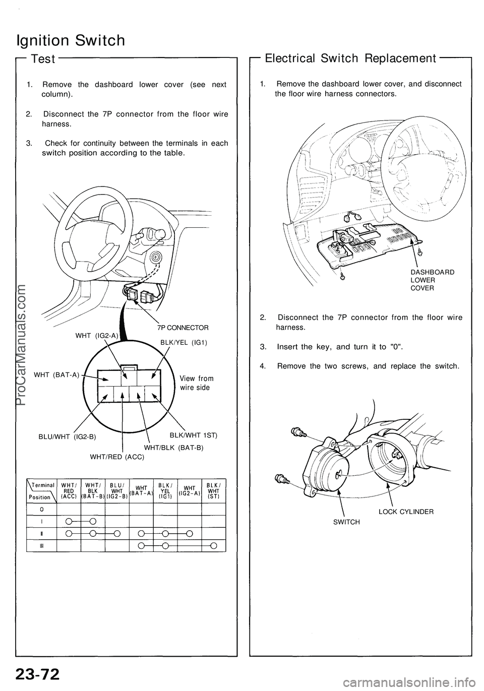
Ignition Switch
Test
1. Remove the dashboard lower cover (see next
column).
2. Disconnect the 7P connector from the floor wire
harness.
3. Check for continuity between the terminals in each
switch position according to the table.
7P CONNECTOR
BLK/YEL (IG1)
BLU/WHT (IG2-B)
View from
wire side
BLK/WHT 1ST)
WHT/BLK (BAT-B)
WHT/RED (ACC)
Electrical Switch Replacement
1. Remove the dashboard lower cover, and disconnect
the floor wire harness connectors.
DASHBOARD
LOWER
COVER
2. Disconnect the 7P connector from the floor wire
harness.
3. Insert the key, and turn it to "0".
4. Remove the two screws, and replace the switch.
LOCK CYLINDER
SWITCH
WHT (IG2-A)
WHT (BAT-A)ProCarManuals.com
Page 1246 of 1503
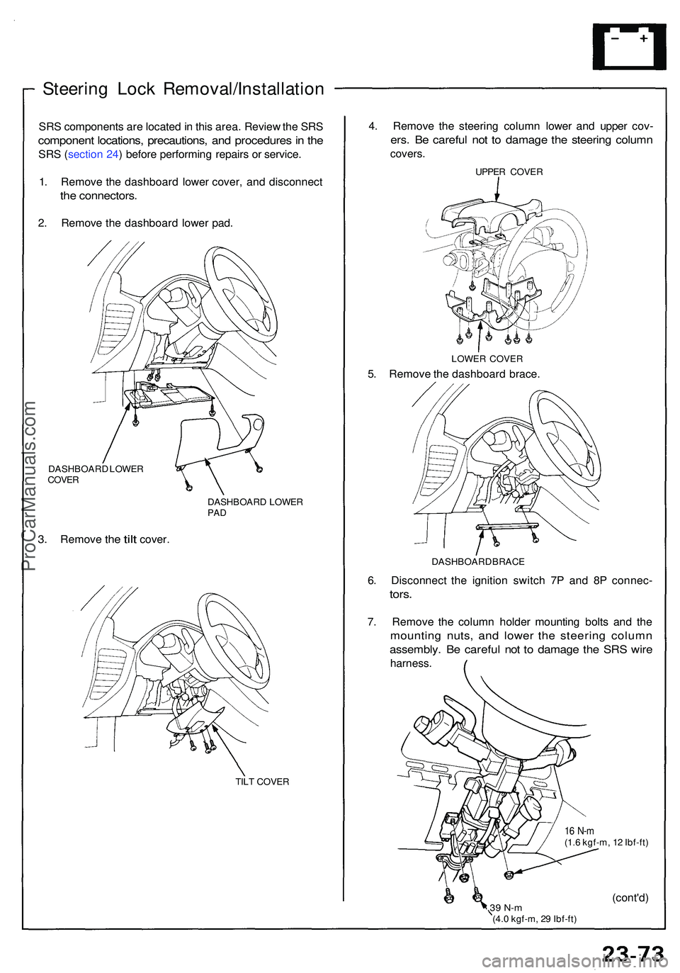
Steering Loc k Removal/Installatio n
SRS component s ar e locate d in thi s area . Revie w th e SR S
componen t locations , precautions , an d procedure s in th e
SR S (sectio n 24 ) befor e performin g repair s o r service .
1 . Remov e th e dashboar d lowe r cover , an d disconnec t
the connectors .
2. Remov e th e dashboar d lowe r pad .
DASHBOAR D LOWE R
COVE R
3. Remov e the tilt cover .
DASHBOAR D LOWE RPAD
TIL T COVE R
4. Remov e th e steerin g colum n lowe r an d uppe r cov -
ers. B e carefu l no t t o damag e th e steerin g colum n
covers .
UPPER COVE R
LOWE R COVE R
5. Remov e th e dashboar d brace .
DASHBOAR D BRAC E
6. Disconnec t th e ignitio n switc h 7 P an d 8 P connec -
tors.
7. Remov e th e colum n holde r mountin g bolt s an d th e
mountin g nuts , an d lowe r th e steerin g colum n
assembly . B e carefu l no t t o damag e th e SR S wir e
harness .
16 N- m(1.6 kgf-m , 1 2 Ibf-ft )
.39 N- m(4.0 kgf-m , 2 9 Ibf-ft )
(cont'd )
ProCarManuals.com
Page 1247 of 1503
Ignition Switch
Steering Lock Removal/Installation (cont'd)
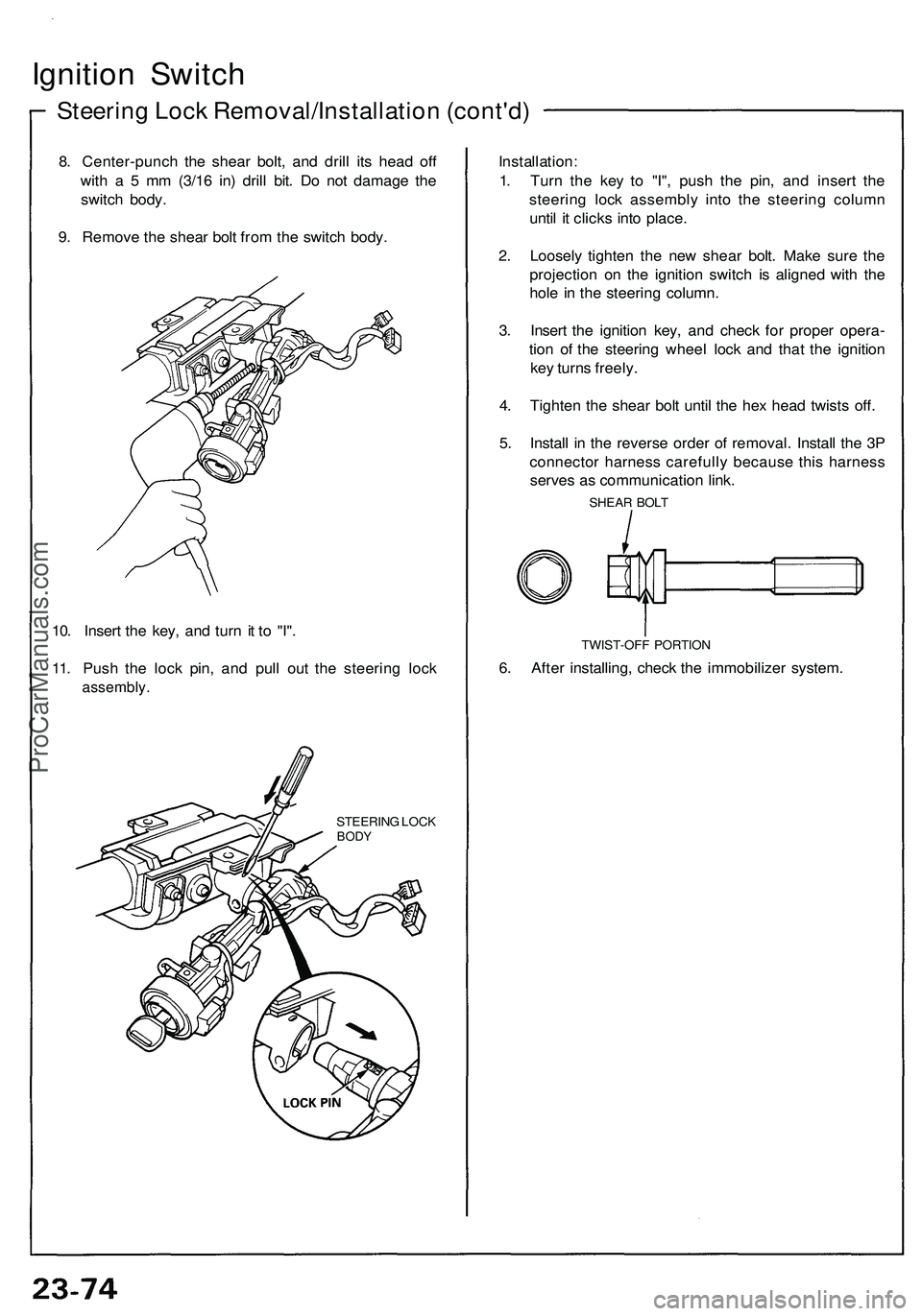
8. Center-punch the shear bolt, and drill its head off
with a 5 mm (3/16 in) drill bit. Do not damage the
switch body.
9. Remove the shear bolt from the switch body.
10. Insert the key, and turn it to "I".
11. Push the lock pin, and pull out the steering lock
assembly.
STEERING LOCK
BODY
Installation:
1. Turn the key to "I", push the pin, and insert the
steering lock assembly into the steering column
until it clicks into place.
2. Loosely tighten the new shear bolt. Make sure the
projection on the ignition switch is aligned with the
hole in the steering column.
3. Insert the ignition key, and check for proper opera-
tion of the steering wheel lock and that the ignition
key turns freely.
4. Tighten the shear bolt until the hex head twists off.
5. Install in the reverse order of removal. Install the 3P
connector harness carefully because this harness
serves as communication link.
SHEAR BOLT
TWIST-OFF PORTION
6. After installing, check the immobilizer system.ProCarManuals.com
Page 1248 of 1503
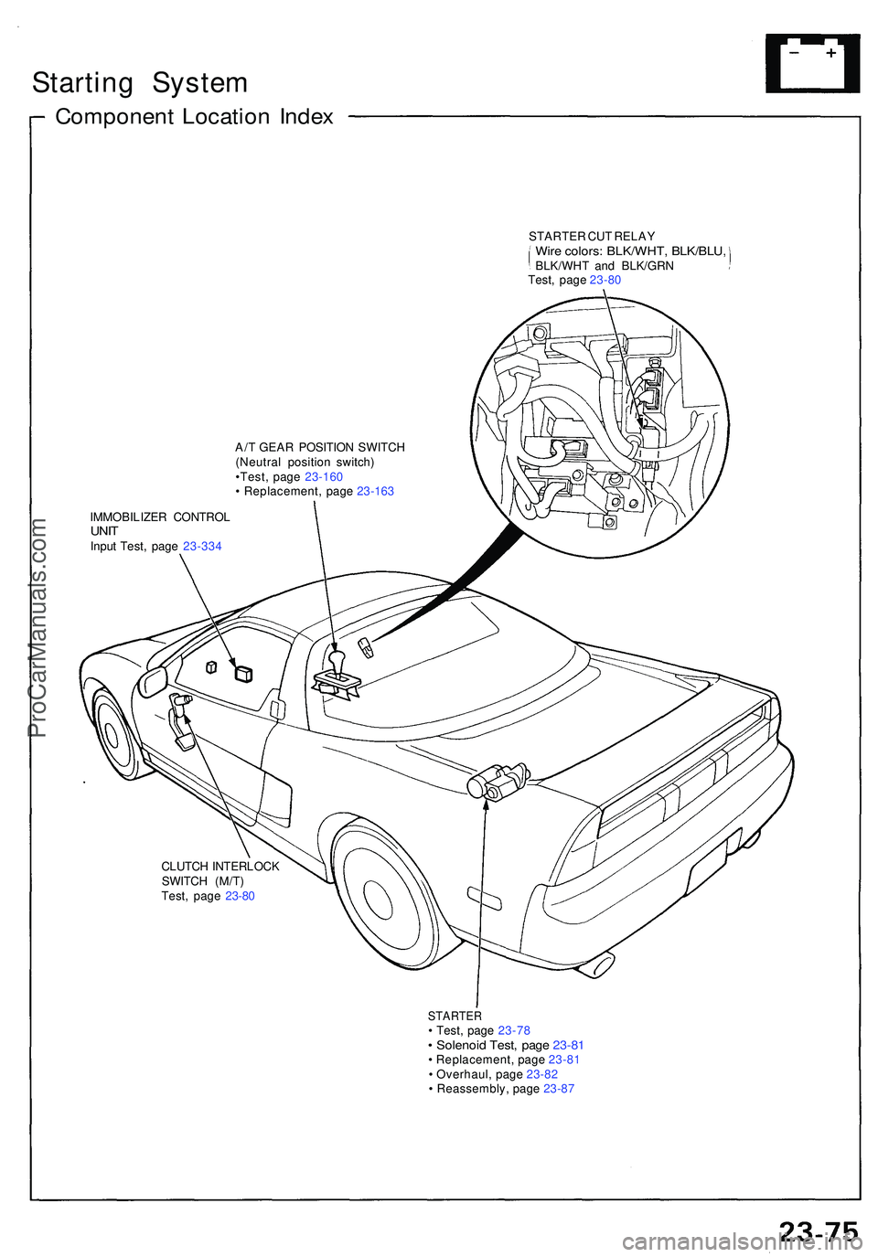
Starting Syste m
Componen t Locatio n Inde x
A/T GEA R POSITIO N SWITC H
(Neutra l positio n switch )
•Test , pag e 23-16 0
• Replacement , pag e 23-163
IMMOBILIZE R CONTRO L
UNITInpu t Test , pag e 23-33 4
CLUTC H INTERLOC K
SWITC H (M/T )
Test , pag e 23-8 0
STARTE R• Test , pag e 23-7 8• Solenoi d Test , pag e 23-8 1• Replacement , pag e 23-8 1
• Overhaul , pag e 23-8 2
• Reassembly , pag e 23-8 7
STARTE
R CU T RELA Y
Wire colors : BLK/WHT , BLK/BLU ,BLK/WHT an d BLK/GR NTest, pag e 23-8 0
ProCarManuals.com
Page 1249 of 1503
Starting Syste m
Descriptio n
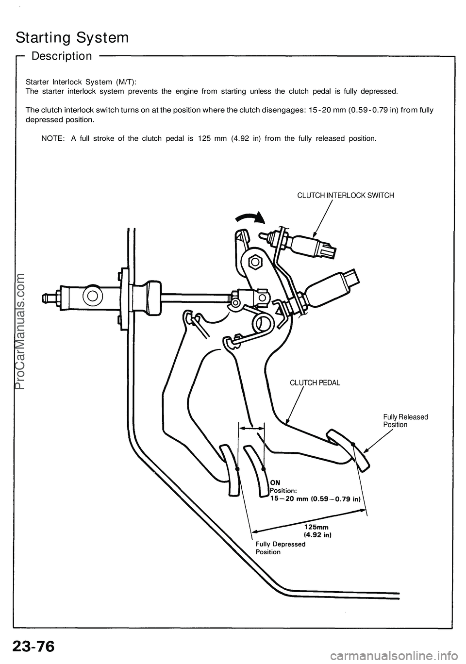
Starter Interloc k Syste m (M/T) :
Th e starte r interloc k syste m prevent s th e engin e fro m startin g unles s th e clutc h peda l i s full y depressed .
The clutc h interloc k switc h turn s o n a t th e positio n wher e th e clutc h disengages : 1 5 - 2 0 m m (0.5 9 - 0.7 9 in ) fro m full y
depresse d position .
NOTE: A ful l strok e o f th e clutc h peda l i s 12 5 m m (4.9 2 in ) fro m th e full y release d position .
CLUTCH INTERLOC K SWITC H
Full y Release d
Positio n
CLUTC
H PEDA L
ProCarManuals.com
Page 1250 of 1503
Starting Syste m
Starte r Tes t
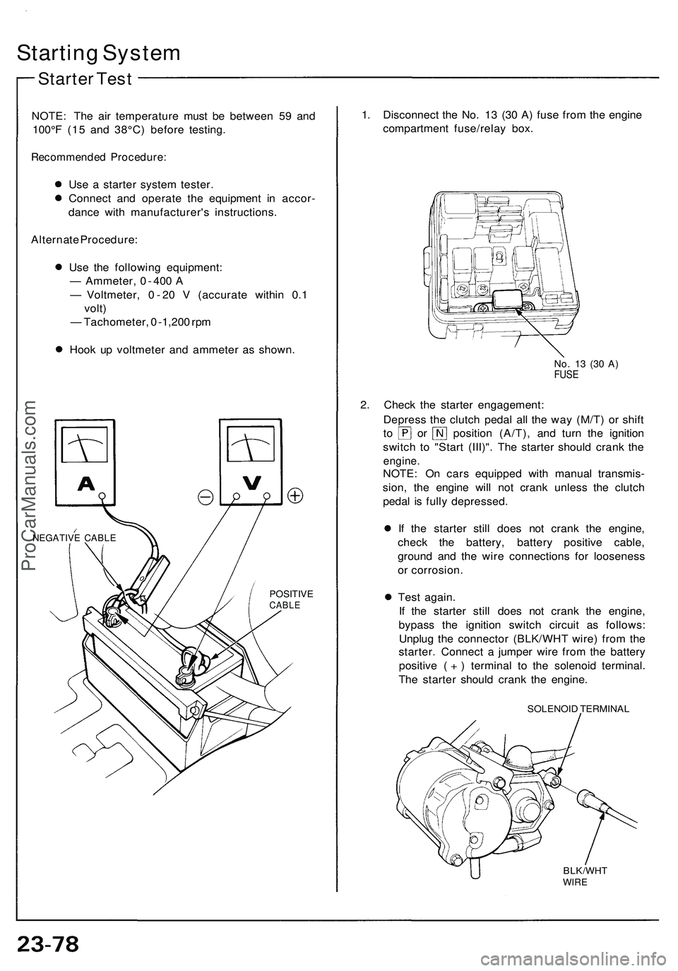
NOTE : Th e ai r temperatur e mus t b e betwee n 5 9 an d
100° F (1 5 an d 38°C ) befor e testing .
Recommende d Procedure :
Use a starte r syste m tester .
Connec t an d operat e th e equipmen t i n accor -
danc e wit h manufacturer' s instructions .
Alternat e Procedure :
Us e th e followin g equipment :
— Ammeter , 0 - 40 0 A
— Voltmeter , 0 - 2 0 V (accurat e withi n 0. 1
volt )
— Tachometer , 0 -1,20 0 rp m
Hoo k u p voltmete r an d ammete r a s shown .
NEGATIV E CABL E
POSITIV ECABLE
1. Disconnec t th e No . 1 3 (3 0 A ) fus e fro m th e engin e
compartmen t fuse/rela y box .
No. 1 3 (3 0 A )FUS E
2. Chec k th e starte r engagement :
Depres s th e clutc h peda l al l th e wa y (M/T ) o r shif t
to o r positio n (A/T) , an d tur n th e ignitio n
switc h t o "Star t (III)" . Th e starte r shoul d cran k th e
engine .
NOTE: O n car s equippe d wit h manua l transmis -
sion , th e engin e wil l no t cran k unles s th e clutc h
peda l i s full y depressed .
I f th e starte r stil l doe s no t cran k th e engine ,
chec k th e battery , batter y positiv e cable ,
ground and th e wir e connection s fo r loosenes s
o r corrosion .
Tes t again .
If th e starte r stil l doe s no t cran k th e engine ,
bypas s th e ignitio n switc h circui t a s follows :
Unplu g th e connecto r (BLK/WH T wire ) fro m th e
starter . Connec t a jumpe r wir e fro m th e batter y
positiv e ( + ) termina l t o th e solenoi d terminal .
Th e starte r shoul d cran k th e engine .
SOLENOI D TERMINA L
BLK/WHTWIRE
ProCarManuals.com