ACURA NSX 1997 Service Owner's Guide
Manufacturer: ACURA, Model Year: 1997, Model line: NSX, Model: ACURA NSX 1997Pages: 1503, PDF Size: 57.08 MB
Page 31 of 1503
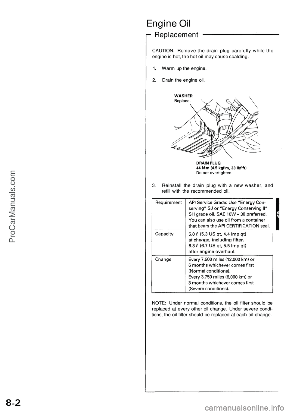
Engine Oi l
Replacemen t
CAUTION: Remov e th e drai n plu g carefull y whil e th e
engin e is hot , th e ho t oi l ma y caus e scalding .
1 . War m u p th e engine .
2 . Drai n th e engin e oil .
3 . Reinstal l th e drai n plu g wit h a ne w washer , an d
refil l wit h th e recommende d oil .
NOTE : Unde r norma l conditions , th e oi l filte r shoul d b e
replace d a t ever y othe r oi l change . Unde r sever e condi -
tions , th e oi l filte r shoul d b e replace d a t eac h oi l change .
ProCarManuals.com
Page 32 of 1503
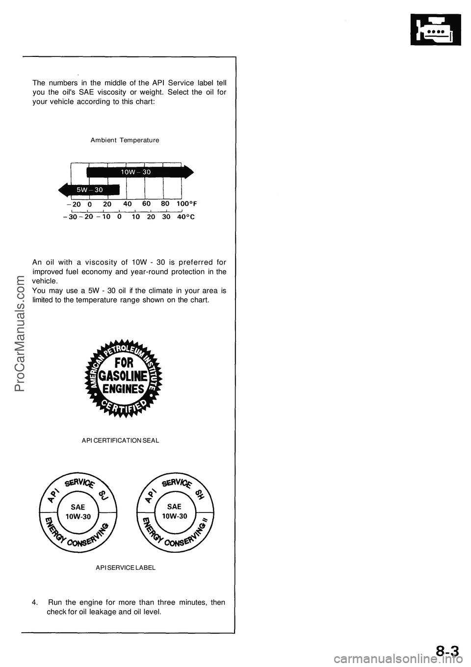
The numbers in the middle of the API Service label tell
you the oil's SAE viscosity or weight. Select the oil for
your vehicle according to this chart:
Ambient Temperature
An oil with a viscosity of 10W - 30 is preferred for
improved fuel economy and year-round protection in the
vehicle.
You may use a 5W - 30 oil if the climate in your area is
limited to the temperature range shown on the chart.
API CERTIFICATION SEAL
API SERVICE LABEL
4. Run the engine for more than three minutes, then
check for oil leakage and oil level.ProCarManuals.com
Page 33 of 1503
Troubleshooting Procedure s
Checking th e Diagnosti c Troubl e Cod e (DTC )
wit h a n OB D II Sca n Too l o r th e Hond a PG M Teste r
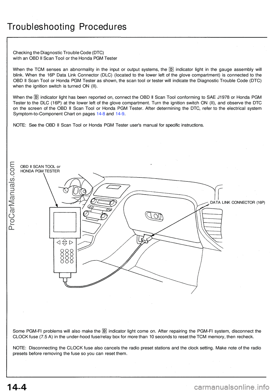
When th e TC M sense s a n abnormalit y i n th e inpu t o r outpu t systems , th e indicato r ligh t i n th e gaug e assembl y wil l
blink . Whe n th e 16 P Dat a Lin k Connecto r (DLC ) (locate d t o th e lowe r lef t o f th e glov e compartment ) i s connecte d t o th e
OB D II Sca n Too l o r Hond a PG M Teste r a s shown , th e sca n too l o r teste r wil l indicat e th e Diagnosti c Troubl e Cod e (DTC )
whe n th e ignitio n switc h i s turne d O N (II) .
Whe n th e indicato r ligh t ha s bee n reporte d on , connec t th e OB D II Sca n Too l conformin g t o SA E J197 8 o r Hond a PG M
Teste r t o th e DL C (16P ) a t th e lowe r lef t o f th e glov e compartment . Tur n th e ignitio n switc h O N (II) , an d observ e th e DT C
o n th e scree n o f th e OB D II Sca n Too l o r Hond a PG M Tester . Afte r determinin g th e DTC , refe r t o th e electrica l syste m
Symptom-to-Componen t Char t o n page s 14- 8 an d 14-9 .
NOTE : Se e th e OB D II Sca n Too l o r Hond a PG M Teste r user' s manua l fo r specifi c instructions .
OBD II SCA N TOO L o r
HOND A PG M TESTE R
DATA LIN K CONNECTO R (16P )
Some PGM-F I problem s wil l als o mak e th e indicato r ligh t com e on . Afte r repairin g th e PGM-F I system , disconnec t th e
CLOC K fus e (7. 5 A ) i n th e under-hoo d fuse/rela y bo x fo r mor e tha n 1 0 second s t o rese t th e TC M memory , the n recheck .
NOTE : Disconnectin g th e CLOC K fus e als o cancel s th e radi o prese t station s an d th e cloc k setting . Mak e not e o f th e radi o
preset s befor e removin g th e fus e s o yo u ca n rese t them .
ProCarManuals.com
Page 34 of 1503
Checking th e Diagnosti c Troubl e Cod e (DTC )
wit h th e Servic e Chec k Connecto r an d Specia l Too l
Whe n th e TC M sense s a n abnormalit y i n th e inpu t o r outpu t systems , th e indicato r ligh t i n th e gaug e assembl y wil l
blink .
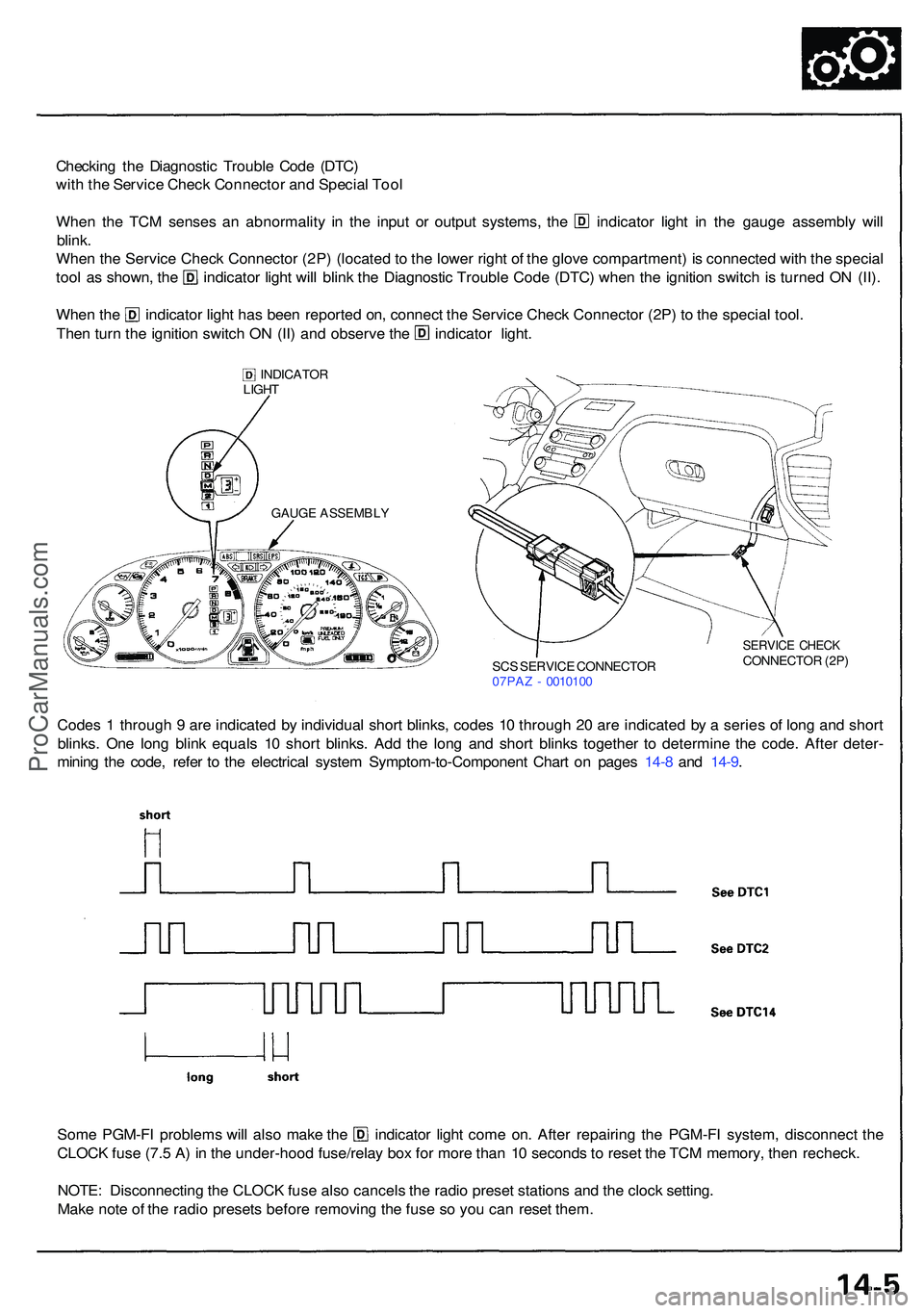
Whe n th e Servic e Chec k Connecto r (2P ) (locate d to th e lowe r righ t o f th e glov e compartment ) i s connecte d wit h th e specia l
tool a s shown , th e indicato r ligh t wil l blin k th e Diagnosti c Troubl e Cod e (DTC ) whe n th e ignitio n switc h i s turne d O N (II) .
Whe n th e indicato r ligh t ha s bee n reporte d on , connec t th e Servic e Chec k Connecto r (2P ) t o th e specia l tool .
Then tur n th e ignitio n switc h O N (II ) an d observ e th e indicato r light .
INDICATO R
LIGH T
SCS SERVIC E CONNECTO R
07PA Z - 001010 0
SERVIC E CHEC KCONNECTO R (2P )
Code s 1 throug h 9 ar e indicate d b y individua l shor t blinks , code s 1 0 throug h 2 0 ar e indicate d b y a serie s o f lon g an d shor t
blinks . On e lon g blin k equal s 1 0 shor t blinks . Ad d th e lon g an d shor t blink s togethe r t o determin e th e code . Afte r deter -
minin g th e code , refe r t o th e electrica l syste m Symptom-to-Componen t Char t o n page s 14-8 an d 14-9 .
Som e PGM-F I problem s wil l als o mak e th e indicato r ligh t com e on . Afte r repairin g th e PGM-F I system , disconnec t th e
CLOC K fus e (7. 5 A ) i n th e under-hoo d fuse/rela y bo x fo r mor e tha n 1 0 second s t o rese t th e TC M memory , the n recheck .
NOTE : Disconnectin g th e CLOC K fus e als o cancel s th e radi o prese t station s an d th e cloc k setting .
Mak e not e o f th e radi o preset s befor e removin g th e fus e s o yo u ca n rese t them .
GAUG E ASSEMBL Y
ProCarManuals.com
Page 35 of 1503
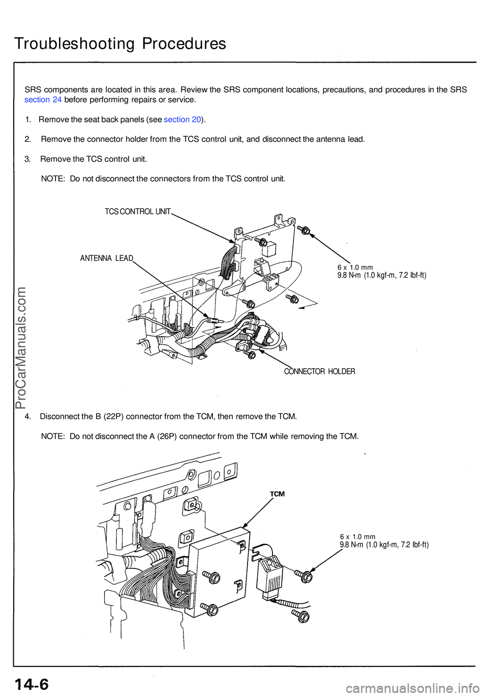
Troubleshooting Procedure s
SRS component s ar e locate d in thi s area . Revie w th e SR S componen t locations , precautions , an d procedure s in th e SR S
sectio n 24 befor e performin g repair s o r service .
1 . Remov e th e sea t bac k panel s (se e sectio n 20 ).
2 . Remov e th e connecto r holde r fro m th e TC S contro l unit , an d disconnec t th e antenn a lead .
3 . Remov e th e TC S contro l unit .
NOTE : D o no t disconnec t th e connector s fro m th e TC S contro l unit .
TCS CONTRO L UNI T
ANTENN A LEA D6 x 1. 0 m m9.8 N- m (1. 0 kgf-m , 7. 2 Ibf-ft )
CONNECTO R HOLDE R
4. Disconnec t th e B (22P ) connecto r fro m th e TCM , the n remov e th e TCM .
NOTE : D o no t disconnec t th e A (26P ) connecto r fro m th e TC M whil e removin g th e TCM .
6 x 1. 0 m m9.8 N- m (1. 0 kgf-m , 7. 2 Ibf-ft )
ProCarManuals.com
Page 36 of 1503
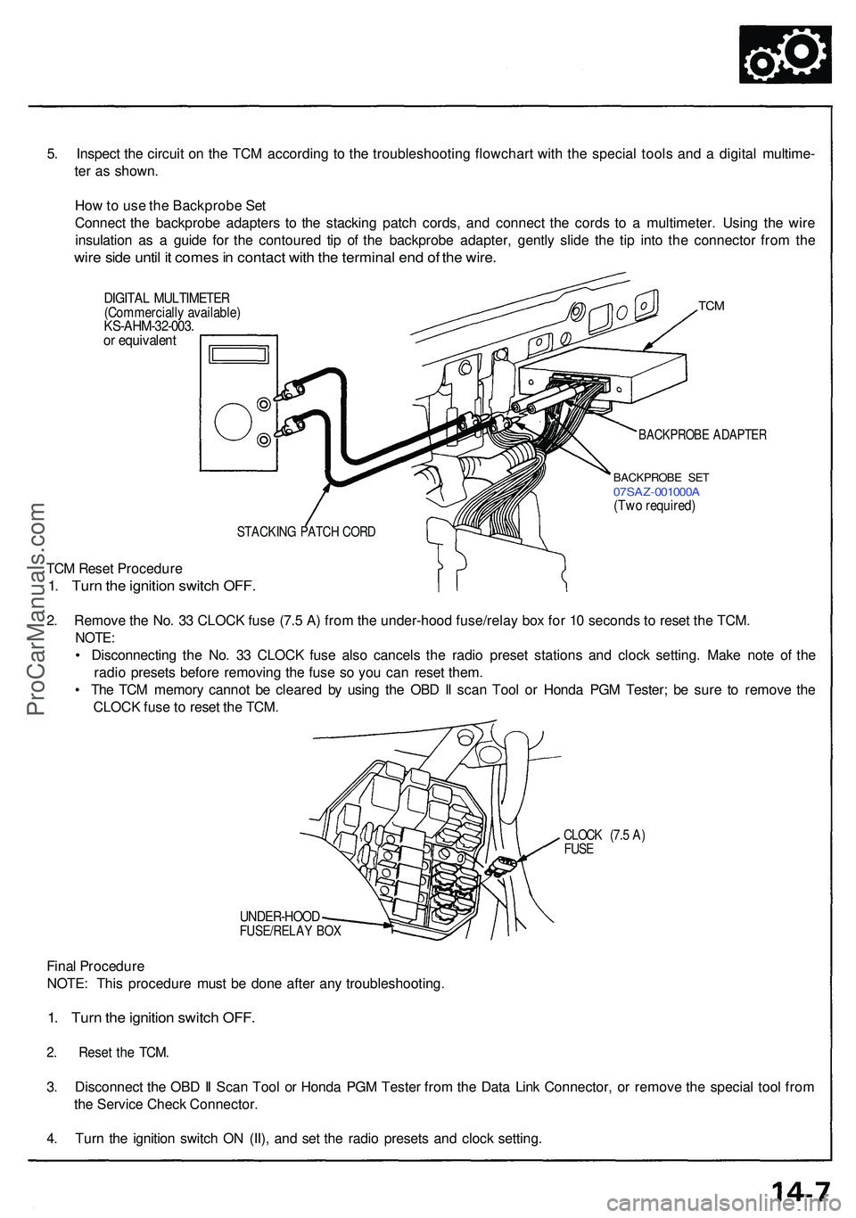
5. Inspec t th e circui t o n th e TC M accordin g t o th e troubleshootin g flowchar t wit h th e specia l tool s an d a digita l multime -
te r a s shown .
Ho w to us e th e Backprob e Se t
Connec t th e backprob e adapter s t o th e stackin g patc h cords , an d connec t th e cord s t o a multimeter . Usin g th e wir e
insulatio n a s a guid e fo r th e contoure d ti p o f th e backprob e adapter , gentl y slid e th e ti p int o th e connecto r fro m th e
wire sid e unti l i t come s in contac t wit h th e termina l en d o f th e wire .
DIGITA L MULTIMETE R(Commerciall y available )KS-AHM-32-003 .or equivalen t
TCM
BACKPROB E ADAPTE R
BACKPROB E SE T07SA Z-001000 A(Two required )
STACKIN G PATC H COR D
TCM Rese t Procedur e
1. Tur n th e ignitio n switc h OFF .
2. Remov e th e No . 3 3 CLOC K fus e (7. 5 A ) fro m th e under-hoo d fuse/rela y bo x fo r 1 0 second s t o rese t th e TCM .
NOTE :
• Disconnectin g th e No . 3 3 CLOC K fus e als o cancel s th e radi o prese t station s an d cloc k setting . Mak e not e o f th e
radi o preset s befor e removin g th e fus e s o yo u ca n rese t them .
• Th e TC M memor y canno t b e cleare d b y usin g th e OB D II sca n Too l o r Hond a PG M Tester ; b e sur e t o remov e th e
CLOC K fus e to rese t th e TCM .
CLOC K (7. 5 A )FUS E
UNDER-HOO DFUSE/RELAY BO X
Fina l Procedur e
NOTE : Thi s procedur e mus t b e don e afte r an y troubleshooting .
1. Tur n th e ignitio n switc h OFF .
2. Rese t th e TCM .
3. Disconnec t th e OB D II Sca n Too l o r Hond a PG M Teste r fro m th e Dat a Lin k Connector , o r remov e th e specia l too l fro m
th e Servic e Chec k Connector .
4 . Tur n th e ignitio n switc h O N (II) , an d se t th e radi o preset s an d cloc k setting .
ProCarManuals.com
Page 37 of 1503
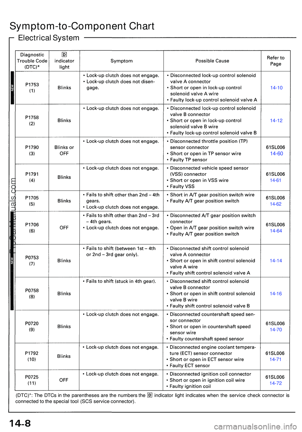
Symptom-to-Component Char t
Electrica l Syste m
14-10
14-1 2
14-60
14-6 1
14-62
14-6 4
14-1 4
14-16
14-7 0
14-71
14-7 2
(DTC)* : Th e DTC s i n th e parenthese s ar e th e number s th e indicato r ligh t indicate s whe n th e servic e chec k connecto r i s
connecte d to th e specia l too l (SC S servic e connector) .
ProCarManuals.com
Page 38 of 1503
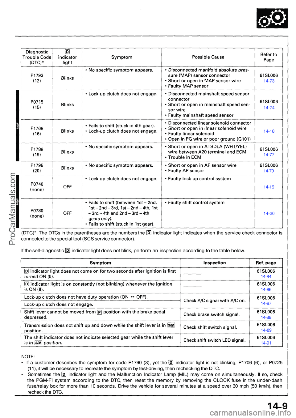
(DTC)*: The DTC s in th e parenthese s ar e th e number s th e indicato r ligh t indicate s whe n th e servic e chec k connecto r i s
connecte d to th e specia l too l (SC S servic e connector) .
If th e self-diagnosti c indicato r ligh t doe s no t blink , perfor m an inspectio n accordin g to th e tabl e below .
NOTE:
• I f a custome r describe s th e sympto m fo r cod e P179 0 (3) , ye t th e indicato r ligh t i s no t blinking , P170 6 (6) , o r P072 5
(11), i t wil l b e necessar y to recreat e th e sympto m by test-driving , the n recheckin g th e DTC .
• Sometime s th e indicato r ligh t an d th e Malfunctio n Indicato r Lam p (MIL ) ma y com e o n simultaneously . I f so , chec k
th e PGM-F I syste m accordin g t o th e DTC , the n rese t th e memor y b y removin g th e CLOC K fus e i n th e under-das h
fuse/rela y bo x fo r mor e tha n 1 0 seconds . Driv e th e vehicl e fo r severa l minute s a t a spee d ove r 3 0 mp h (5 0 km/h) , the n
rechec k th e DTC .
14-73
14-7 4
14-18
14-7 7
14-79
14-19
14-2 0
14-84
14-8 6
14-87
14-8 8
14-8 9
14-91
ProCarManuals.com
Page 39 of 1503
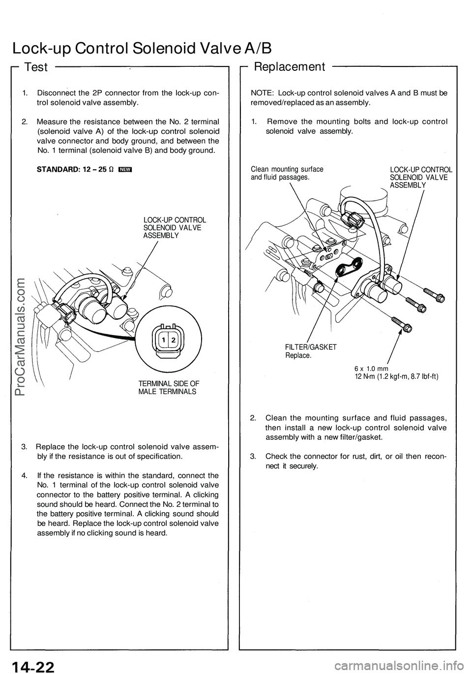
Lock-up Contro l Solenoi d Valv e A/ B
Replacemen t
1. Disconnec t th e 2 P connecto r fro m th e lock-u p con -
tro l solenoi d valv e assembly .
2 . Measur e th e resistanc e betwee n th e No . 2 termina l
(solenoid valv e A ) o f th e lock-u p contro l solenoi d
valve connecto r an d bod y ground , an d betwee n th e
No . 1 termina l (solenoi d valv e B ) an d bod y ground .
LOCK-U P CONTRO L
SOLENOI D VALV E
ASSEMBL Y
TERMINAL SID E O FMAL E TERMINAL S
3. Replac e th e lock-u p contro l solenoi d valv e assem -
bl y if th e resistanc e is ou t o f specification .
4 . I f th e resistanc e i s withi n th e standard , connec t th e
No . 1 termina l o f th e lock-u p contro l solenoi d valv e
connecto r t o th e batter y positiv e terminal . A clickin g
soun d shoul d b e heard . Connec t th e No . 2 termina l t o
th e batter y positiv e terminal . A clickin g soun d shoul d
b e heard . Replac e th e lock-u p contro l solenoi d valv e
assembl y if n o clickin g soun d is heard . NOTE
: Lock-u p contro l solenoi d valve s A an d B mus t b e
removed/replace d a s a n assembly .
1 . Remov e th e mountin g bolt s an d lock-u p contro l
solenoi d valv e assembly .
Clean mountin g surfac e
an d flui d passages . LOCK-U
P CONTRO L
SOLENOI D VALV E
ASSEMBL Y
FILTER/GASKE TReplace.
6 x 1. 0 m m12 N- m (1. 2 kgf-m , 8. 7 Ibf-ft )
2. Clea n th e mountin g surfac e an d flui d passages ,
the n instal l a ne w lock-u p contro l solenoi d valv e
assembl y wit h a ne w filter/gasket .
3 . Chec k th e connecto r fo r rust , dirt , o r oi l the n recon -
nec t i t securely .
Test
ProCarManuals.com
Page 40 of 1503
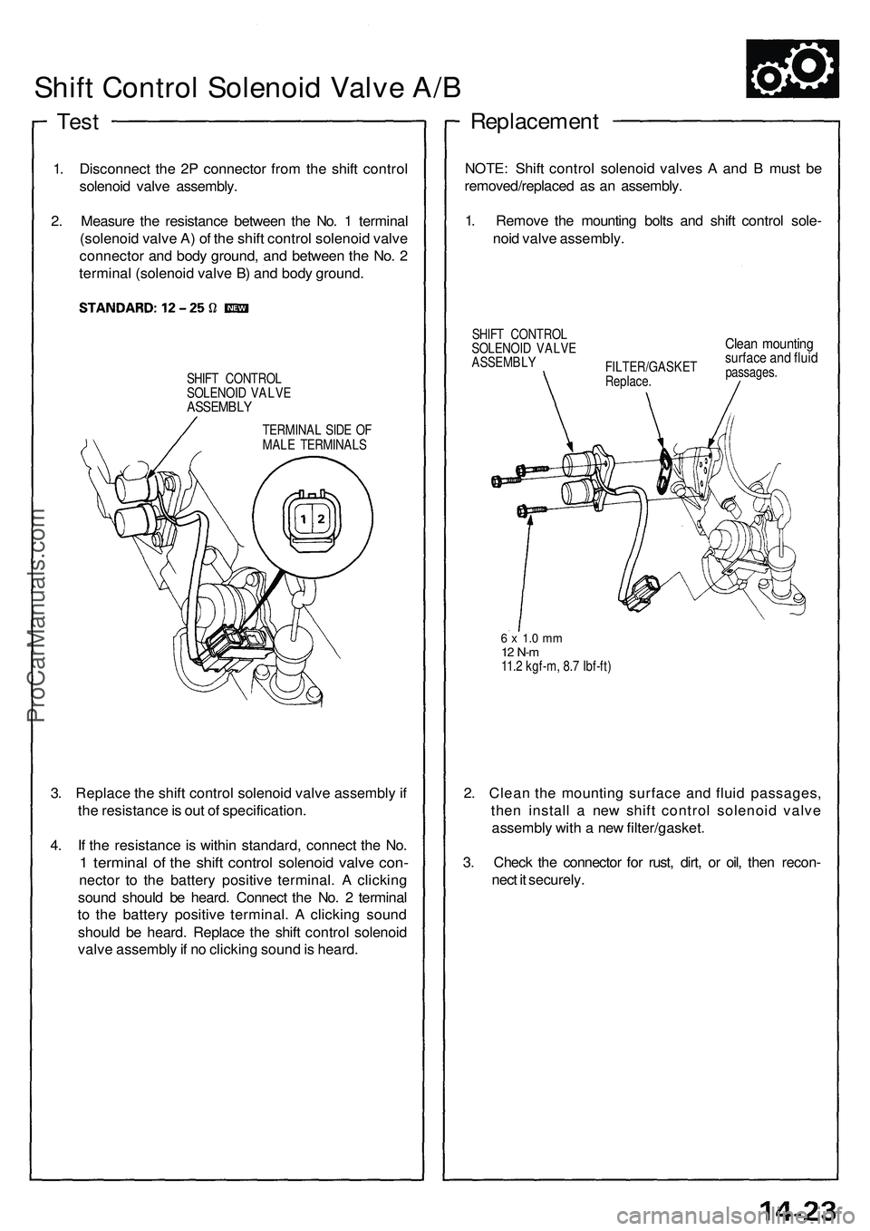
Shift Contro l Solenoi d Valv e A/ B
Tes t
1. Disconnec t th e 2 P connecto r fro m th e shif t contro l
solenoi d valv e assembly .
2 . Measur e th e resistanc e betwee n th e No . 1 termina l
(solenoi d valv e A ) o f th e shif t contro l solenoi d valv e
connecto r an d bod y ground , an d betwee n th e No . 2
termina l (solenoi d valv e B ) an d bod y ground .
SHIFT CONTRO L
SOLENOI D VALV E
ASSEMBL Y
TERMINAL SID E O F
MAL E TERMINAL S
3. Replac e th e shif t contro l solenoi d valv e assembl y if
th e resistanc e is ou t o f specification .
4 . I f th e resistanc e is withi n standard , connec t th e No .
1 termina l o f th e shif t contro l solenoi d valv e con -
necto r t o th e batter y positiv e terminal . A clickin g
soun d shoul d b e heard . Connec t th e No . 2 termina l
t o th e batter y positiv e terminal . A clickin g soun d
shoul d b e heard . Replac e th e shif t contro l solenoi d
valv e assembl y if n o clickin g soun d is heard .
Replacemen t
NOTE: Shif t contro l solenoi d valve s A an d B mus t b e
removed/replace d a s a n assembly .
1 . Remov e th e mountin g bolt s an d shif t contro l sole -
noi d valv e assembly .
SHIFT CONTRO L
SOLENOI D VALV E
ASSEMBL Y
FILTER/GASKE T
Replace .Clean mountin gsurface an d flui dpassages .
6 x 1. 0 m m12 N- m11. 2 kgf-m , 8. 7 Ibf-ft )
2. Clea n th e mountin g surfac e an d flui d passages ,
the n instal l a ne w shif t contro l solenoi d valv e
assembl y wit h a ne w filter/gasket .
3 . Chec k th e connecto r fo r rust , dirt , o r oil , the n recon -
nec t i t securely .
ProCarManuals.com