ACURA RL KA9 1996 Service Repair Manual
Manufacturer: ACURA, Model Year: 1996, Model line: RL KA9, Model: ACURA RL KA9 1996Pages: 1954, PDF Size: 61.44 MB
Page 401 of 1954
Cylinder Head s
Remova l
Make sur e jack s an d safet y stand s ar e
place d properl y an d hois t bracket s ar e attache d t o th e
correc t position s o n th e engine .
CAUTION :
Us e fende r cover s t o avoi d damagin g painte d sur -
faces .
Unplu g th e wirin g connector s carefull y whil e holdin g
th e connecto r portio n to avoi d damage .
T o avoi d damagin g th e cylinde r head , wai t unti l th e
engin e coolan t temperatur e drop s belo w 100° F (38°C )
befor e loosenin g th e retainin g bolts .
NOTE :
Unspecifie d item s ar e common .
Mar k al l wirin g an d hose s t o avoi d misconnection .
Also , b e sur e tha t the y d o no t contac t othe r wirin g o r
hose s o r interfer e wit h othe r parts .
Inspec t th e timin g bel t befor e removin g th e cylinde r
head.
Turn th e crankshaf t pulle y s o tha t th e No . 1 pisto n i s
a t to p dea d cente r (TDC) .
D o th e PC M Memor y Settin g afte r reconnectin g th e
batter y (se e sectio n 11 ).
1 . Remov e th e suppor t strut s fro m th e hood . Fi x th e
hoo d i n a vertica l position , the n reinstal l th e sup -
por t strut s b y usin g 6 x 1. 0 m m bolt s (se e pag e 5-3 ).
2 . Mak e sur e yo u hav e th e anti-thef t cod e fo r th e radio ,
the n writ e dow n th e frequencie s fo r th e radio' s pre -
set buttons .
3. Disconnec t th e batter y negativ e termina l first , the n
th e positiv e terminal .
4 . Drai n th e engin e coolan t (se e pag e 10-5 ).
5 . Remov e th e stru t brac e (se e pag e 5-3 ).
6 . Remov e th e engine cover (se e pag e 5-3 ).
7 . Remov e th e intak e ai r duc t an d ai r cleane r housin g
assembl y (se e pag e 5-4 ). 8
. Remov e th e throttl e cove r (se e pag e 5-4 ).
9 . Remov e th e throttl e cabl e an d cruis e contro l cabl e
b y loosenin g th e locknuts , the n sli p th e cabl e end s
ou t o f th e accelerato r linkag e (se e pag e 5-4 ).
NOTE :
Take car e no t t o ben d th e cabl e whe n removin g
it . Alway s replac e an y kinke d cabl e wit h a ne w
one .
Adjus t th e throttl e cabl e whe n installin g (se e
sectio n 11 ).
Adjus t th e cruis e contro l cabl e whe n installin g
(se e sectio n 23 ).
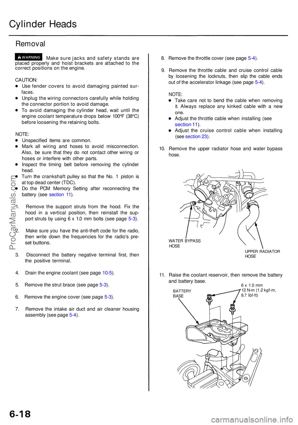
10 . Remov e th e uppe r radiato r hos e an d wate r bypas s
hose.
WATE R BYPAS SHOSEUPPE R RADIATO RHOSE
11. Rais e th e coolan t reservoir , the n remov e th e batter y
an d batter y base .
BATTER YBASE
6 x 1. 0 m m12 N- m (1. 2 kgf-m ,8.7 Ibf-ft )
ProCarManuals.com
Page 402 of 1954
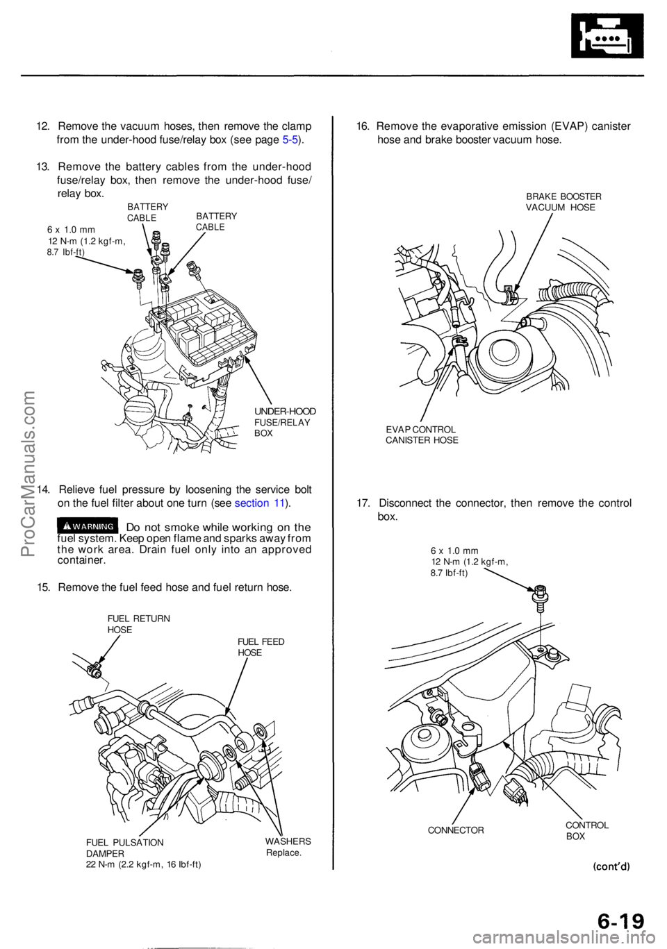
12. Remov e th e vacuu m hoses , the n remov e th e clam p
fro m th e under-hoo d fuse/rela y bo x (se e pag e 5-5 ).
13 . Remov e th e batter y cable s fro m th e under-hoo d
fuse/rela y box , the n remov e th e under-hoo d fuse /
rela y box .
UNDER-HOO DFUSE/RELAYBOX
14. Reliev e fue l pressur e b y loosenin g th e servic e bol t
o n th e fue l filte r abou t on e tur n (se e sectio n 11 ).
D o no t smok e whil e workin g o n th efue l system . Kee p ope n flam e an d spark s awa y fro m
th e wor k area . Drai n fue l onl y int o a n approve d
container.
15. Remov e th e fue l fee d hos e an d fue l retur n hose .
FUEL RETUR NHOSEFUEL FEE D
HOS E
FUE L PULSATIO N
DAMPE R
2 2 N- m (2. 2 kgf-m , 1 6 Ibf-ft )
WASHER SReplace.
16. Remov e th e evaporativ e emissio n (EVAP ) caniste r
hos e an d brak e booste r vacuu m hose .
BRAK E BOOSTE RVACUUM HOS E
EVA P CONTRO L
CANISTE R HOS E
17. Disconnec t th e connector , the n remov e th e contro l
box.
6 x 1. 0 m m12 N- m (1. 2 kgf-m ,
8. 7 Ibf-ft )
CONNECTO R CONTRO
L
BOX
BATTER YCABLE
BATTER YCABLE6 x 1. 0 m m12 N- m (1. 2 kgf-m ,8.7 Ibf-ft )
ProCarManuals.com
Page 403 of 1954
Cylinder Head s
Remova l (cont'd )
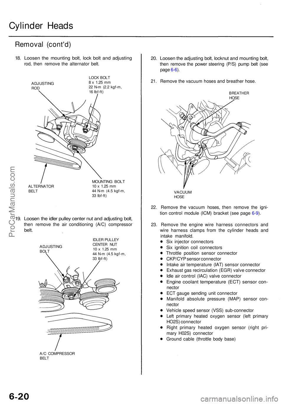
18. Loose n th e mountin g bolt , loc k bol t an d adjustin g
rod, the n remov e th e alternato r belt .
ADJUSTIN GROD
LOC K BOL T8 x 1.2 5 mm22 N- m (2. 2 kgf-m ,
1 6 Ibf-ft )
ALTERNATO R
BELT
MOUNTIN G BOL T10 x 1.2 5 mm44 N- m (4. 5 kgf-m ,
3 3 Ibf-ft )
19. Loose n th e idle r pulle y cente r nu t an d adjustin g bolt ,
then remov e th e ai r conditionin g (A/C ) compresso r
belt.
ADJUSTIN GBOLT IDLE
R PULLE Y
CENTE R NU T10 x 1.2 5 mm44 N- m (4. 5 kgf-m ,
3 3 Ibf-ft )
A/ C COMPRESSO R
BELT
20. Loose n th e adjustin g bolt , locknu t an d mountin g bolt ,
then remov e th e powe r steerin g (P/S ) pum p bel t (se e
pag e 6-6 ).
21 . Remov e th e vacuu m hose s an d breathe r hose .
22 . Remov e th e vacuu m hoses , the n remov e th e igni -
tio n contro l modul e (ICM ) bracke t (se e pag e 6-9 ).
23 . Remov e th e engin e wir e harnes s connector s an d
wir e harnes s clamp s fro m th e cylinde r head s an d
intak e manifold .
Si x injecto r connector s
Si x ignitio n coi l connector s
Throttl e positio n senso r connecto r
CKP/CY P senso r connecto r
Intak e ai r temperatur e (IAT ) senso r connecto r
Exhaus t ga s recirculatio n (EGR ) valv e connecto r
Idl e ai r contro l (IAC ) valv e connecto r
Engine coolan t temperatur e (ECT ) senso r con -
necto r
EC T gaug e sendin g uni t connecto r
Manifol d absolut e pressur e (MAP ) senso r con -
necto r
Vehicl e spee d senso r (VSS ) sub-connecto r
Lef t primar y heate d oxyge n senso r (lef t primar y
HO2S ) connecto r
Righ t primar y heate d oxyge n senso r (righ t pri -
mar y H02S ) connecto r
Groun d cabl e (throttl e bod y base )
VACUU MHOSE
BREATHE RHOSE
ProCarManuals.com
Page 404 of 1954
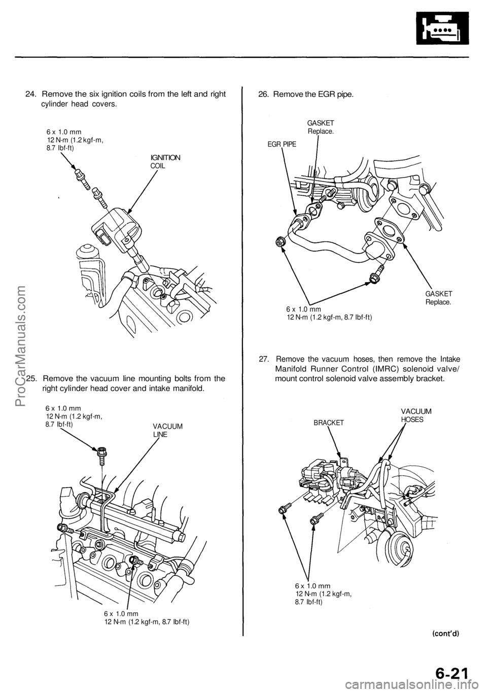
24. Remove the six ignition coils from the left and right
cylinder head covers.
6 x 1.0 mm
12 N-m (1.2 kgf-m,
8.7 Ibf-ft)
IGNITION
COIL
25. Remove the vacuum line mounting bolts from the
right cylinder head cover and intake manifold.
6 x 1.0 mm
12 N-m (1.2 kgf-m,
8.7 Ibf-ft)
VACUUM
LINE
6 x 1.0 mm
12 N-m (1.2 kgf-m, 8.7 Ibf-ft)
26. Remove the EGR pipe.
GASKET
Replace.
EGR PIPE
6 x 1.0 mm
12 N-m (1.2 kgf-m, 8.7 Ibf-ft)
GASKET
Replace.
27. Remove the vacuum hoses, then remove the Intake
Manifold Runner Control (IMRC) solenoid valve/
mount control solenoid valve assembly bracket.
BRACKET
VACUUM
HOSES
6 x 1.0 mm
12 N-m (1.2 kgf-m,
8.7 Ibf-ft)ProCarManuals.com
Page 405 of 1954
Cylinder Head s
Remova l (cont'd )
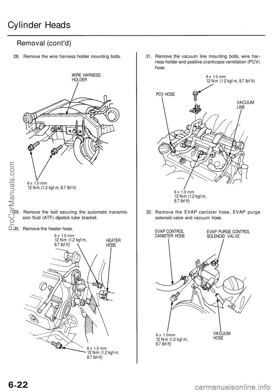
28. Remov e th e wir e harnes s holde r mountin g bolts .
WIRE HARNES SHOLDER
6 x 1. 0 m m12 N- m (1. 2 kgf-m , 8. 7 Ibf-ft )
29. Remov e th e bol t securin g th e automati c transmis -
sio n flui d (ATF ) dipstic k tub e bracket .
30 . Remov e th e heate r hose .
6 x 1. 0 m m12 N- m (1. 2 kgf-m ,
8. 7 Ibf-ft )HEATE RHOSE
6 x 1. 0 m m12 N- m (1. 2 kgf-m ,
8. 7 Ibf-ft )
31. Remov e th e vacuu m lin e mountin g bolts , wir e har -
nes s holde r an d positiv e crankcas e ventilatio n (PCV )
hose.
PCV HOS E
VACUU MLINE
32. Remov e th e EVA P caniste r hose , EVA P purg e
solenoi d valv e an d vacuu m hose .
EVAP CONTRO L
CANISTE R HOS E EVA
P PURG E CONTRO L
SOLENOI D VALV E
6 x 1.0m m12 N- m (1. 2 kgf-m ,
8. 7 Ibf-ft )
VACUU MHOSE
6 x 1. 0 m m12 N- m (1. 2 kgf-m , 8. 7 Ibf-ft )
6 x 1. 0 m m12 N- m (1. 2 kgf-m ,8.7 Ibf-ft )
ProCarManuals.com
Page 406 of 1954
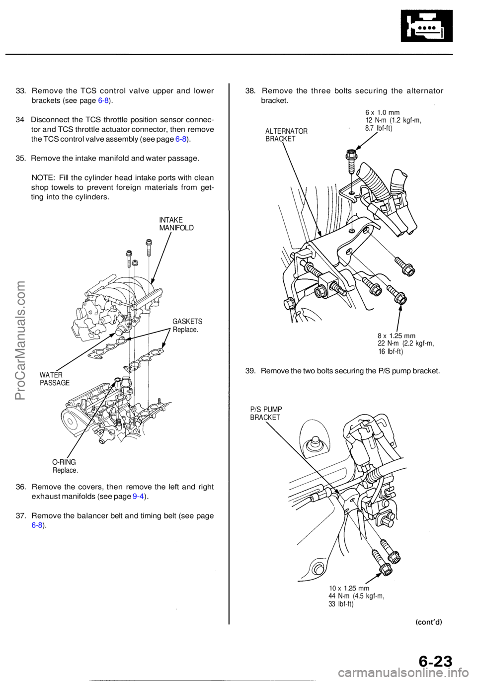
33. Remov e th e TC S contro l valv e uppe r an d lowe r
bracket s (se e pag e 6-8 ).
3 4 Disconnec t th e TC S throttl e positio n senso r connec -
to r an d TC S throttl e actuato r connector , the n remov e
th e TC S contro l valv e assembl y (se e pag e 6-8 ).
35 . Remov e th e intak e manifol d an d wate r passage .
NOTE : Fil l th e cylinde r hea d intak e port s wit h clea n
sho p towel s t o preven t foreig n material s fro m get -
tin g int o th e cylinders .
INTAKEMANIFOL D
WATER
PASSAG E GASKET
S
Replace .
36. Remov e th e covers , the n remov e th e lef t an d righ t
exhaus t manifold s (se e pag e 9-4 ).
37 . Remov e th e balance r bel t an d timin g bel t (se e pag e
6-8).
38 . Remov e th e thre e bolt s securin g th e alternato r
bracket.
ALTERNATO RBRACKET
6 x 1. 0 m m12 N- m (1. 2 kgf-m ,
8. 7 Ibf-ft )
39. Remov e th e tw o bolt s securin g th e P/ S pum p bracket .
P/S PUM PBRACKE T
10 x 1.2 5 mm44 N- m (4. 5 kgf-m ,
3 3 Ibf-ft )
8 x 1.2 5 mm22 N- m (2. 2 kgf-m ,
1 6 Ibf-ft )
O-RIN GReplace .
ProCarManuals.com
Page 407 of 1954
Cylinder Heads
Removal (cont'd)
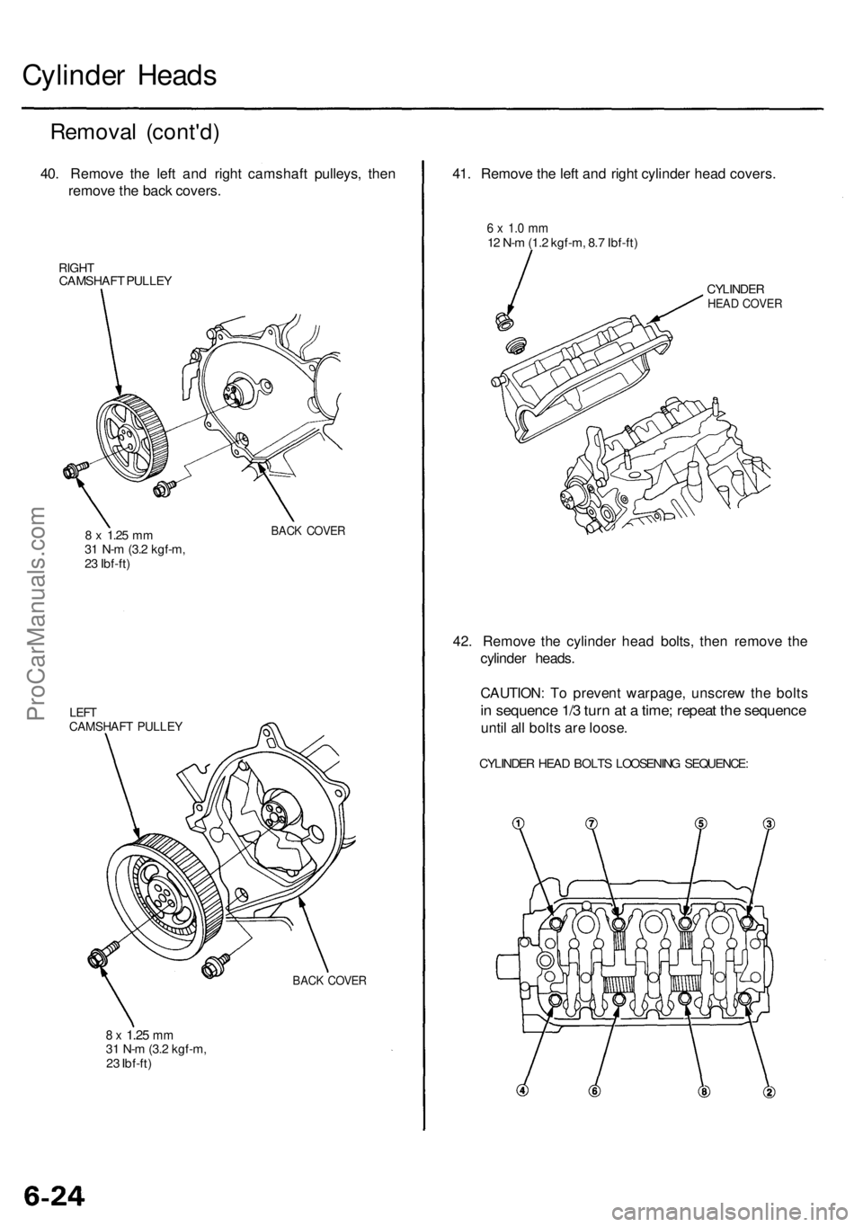
40. Remove the left and right camshaft pulleys, then
remove the back covers.
RIGHT
CAMSHAFT PULLEY
8 x
1.25
mm
31 N-m (3.2 kgf-m,
23 Ibf-ft)
LEFT
CAMSHAFT PULLEY
8 x
1.25
mm
31 N-m (3.2 kgf-m,
23 Ibf-ft)
BACK COVER
BACK COVER
41. Remove the left and right cylinder head covers.
6 x 1.0 mm
12 N-m (1.2 kgf-m, 8.7 Ibf-ft)
CYLINDER
HEAD COVER
42. Remove the cylinder head bolts, then remove the
cylinder heads.
CAUTION: To prevent warpage, unscrew the bolts
in sequence 1/3 turn at a time; repeat the sequence
until all bolts are loose.
CYLINDER HEAD BOLTS LOOSENING SEQUENCE:ProCarManuals.com
Page 408 of 1954
Rocker Ar m Assembl y
Disassembly/Reassembl y
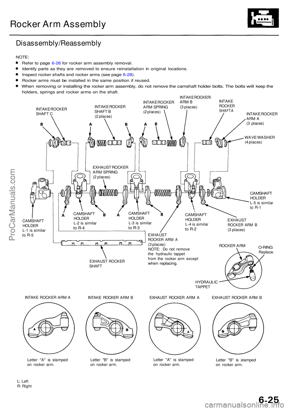
NOTE:
Refer t o pag e 6-2 6 fo r rocke r ar m assembl y removal .
Identif y part s a s the y ar e remove d t o ensur e reinstallatio n i n origina l locations .
Inspec t rocke r shaft s an d rocke r arm s (se e pag e 6-28 ).
Rocke r arm s mus t b e installe d in th e sam e positio n i f reused.
Whe n removin g or installin g the rocke r arm assembly , do no t remov e the camshaf t holder bolts. The bolt s will kee p the
holders , spring s an d rocke r arm s o n th e shaft .
INTAK E ROCKE R
SHAF T C INTAK
E ROCKE R
SHAF T B
( 2 places ) INTAK
EROCKE RSHAFT AINTAKE ROCKE RARM A(3 places )
WAV E WASHE R
( 4 places )
CAMSHAF THOLDERL-5 is simila rto R- 1
CAMSHAF THOLDERL-1 i s simila rto R- 5
EXHAUS T ROCKE RSHAFT
HYDRAULIC
TAPPET
EXHAUS TROCKER AR M B(3 places )
ROCKE R AR M
O-RIN GReplace .
INTAK E ROCKE R AR M A
INTAKE ROCKE R AR M B EXHAUST ROCKE R AR M A EXHAUST ROCKE R AR M B
Lette r "A " i s stampe d
o n rocke r arm . Lette
r "B " i s stampe d
o n rocke r arm . Lette
r "A " i s stampe d
o n rocke r arm . Lette
r "B " i s stampe d
o n rocke r arm .
L : Lef t
R : Righ t INTAK
E ROCKE R
AR M SPRIN G
( 2 places ) INTAK
E ROCKE R
ARM B(3 places )
EXHAUS T ROCKE R
AR M SPRIN G
( 2 places )
CAMSHAF T
HOLDERL-2 is simila rto R- 4
CAMSHAF THOLDERL-3 is simila rto R- 3
EXHAUS TROCKER AR M A(3 places )
NOTE : D o no t remov e
th e hydrauli c tappe t
fro m th e rocke r ar m excep t
when replacing .
\CAMSHAF THOLDERL-4 is simila rto R- 2
ProCarManuals.com
Page 409 of 1954
Rocker Ar m Assembl y
Removal
NOTE:
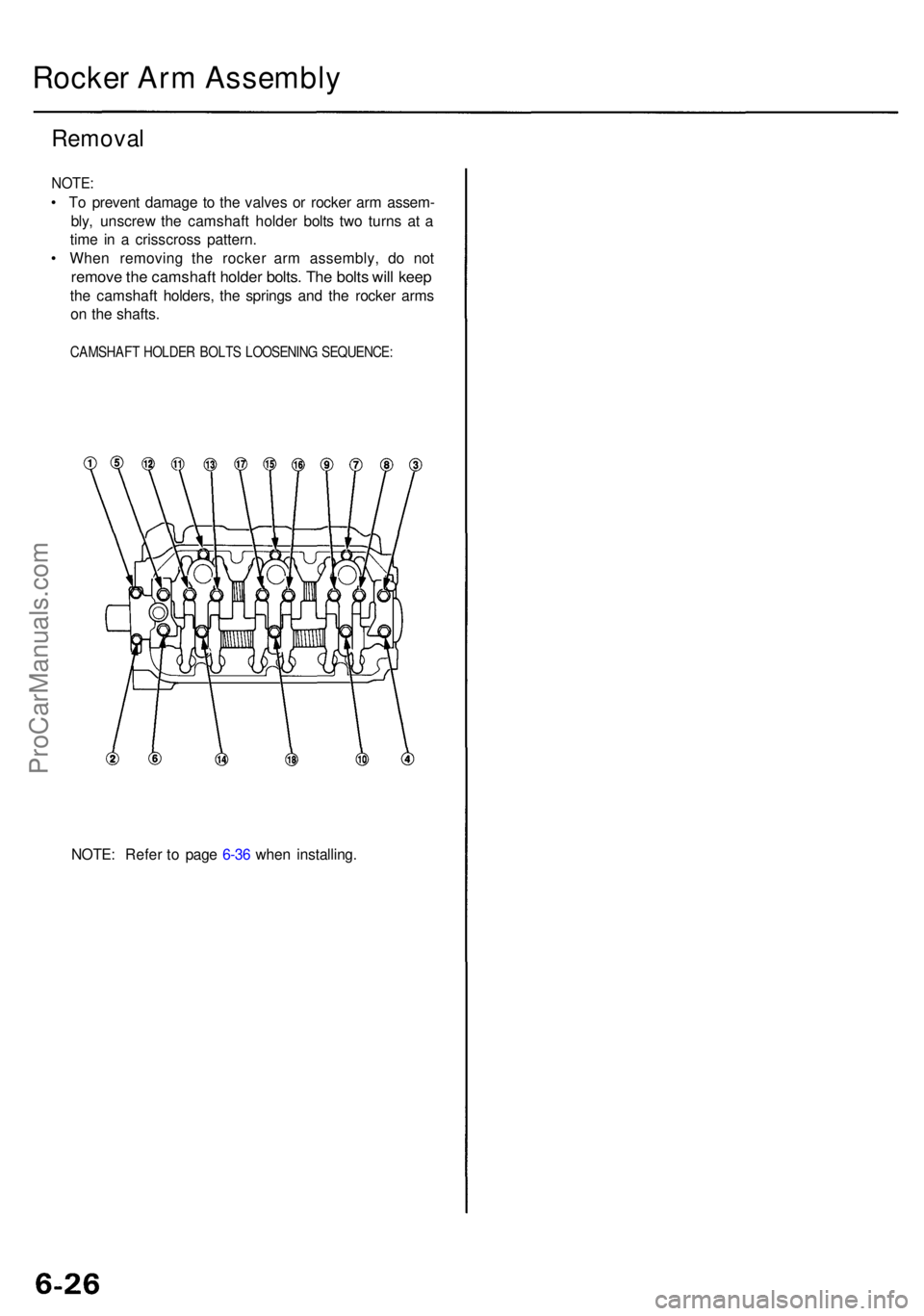
• T o preven t damag e t o th e valve s o r rocke r ar m assem -
bly , unscre w th e camshaf t holde r bolt s tw o turn s a t a
tim e i n a crisscros s pattern .
• Whe n removin g th e rocke r ar m assembly , d o no t
remov e th e camshaf t holde r bolts . Th e bolt s wil l kee p
the camshaf t holders , th e spring s an d th e rocke r arm s
o n th e shafts .
CAMSHAF T HOLDE R BOLT S LOOSENIN G SEQUENCE :
NOTE: Refe r t o pag e 6-3 6 whe n installing .
ProCarManuals.com
Page 410 of 1954
Camshaft
Inspection
NOTE:
• Do not rotate the camshaft during inspection.
• Remove the rocker arms and rocker shafts.
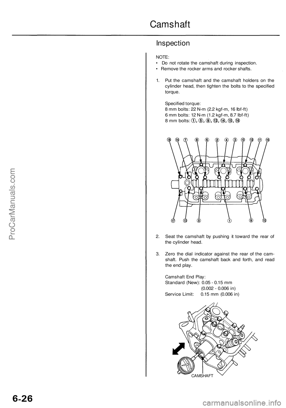
1. Put the camshaft and the camshaft holders on the
cylinder head, then tighten the bolts to the specified
torque.
Specified torque:
8 mm bolts: 22 N-m (2.2 kgf-m, 16 Ibf-ft)
6 mm bolts: 12 N-m (1.2 kgf-m, 8.7 Ibf-ft)
8 mm bolts:
2. Seat the camshaft by pushing it toward the rear of
the cylinder head.
3. Zero the dial indicator against the rear of the cam-
shaft. Push the camshaft back and forth, and read
the end play.
Camshaft End Play:
Standard (New): 0.05 - 0.15 mm
(0.002 - 0.006 in)
Service Limit: 0.15 mm (0.006 in)
CAMSHAFTProCarManuals.com