ACURA RL KA9 1996 Service Repair Manual
Manufacturer: ACURA, Model Year: 1996, Model line: RL KA9, Model: ACURA RL KA9 1996Pages: 1954, PDF Size: 61.44 MB
Page 411 of 1954
4. Remove the bolts, then remove the camshaft hold-
ers from the cylinder head.
5. Lift the camshaft out of the cylinder head, wipe it
clean, then inspect the lift ramps. Replace the
camshaft if any lobes are pitted, scored, or excessively
worn.
6. Clean the camshaft bearing surfaces in the cylinder
head, then set the camshaft back in place.
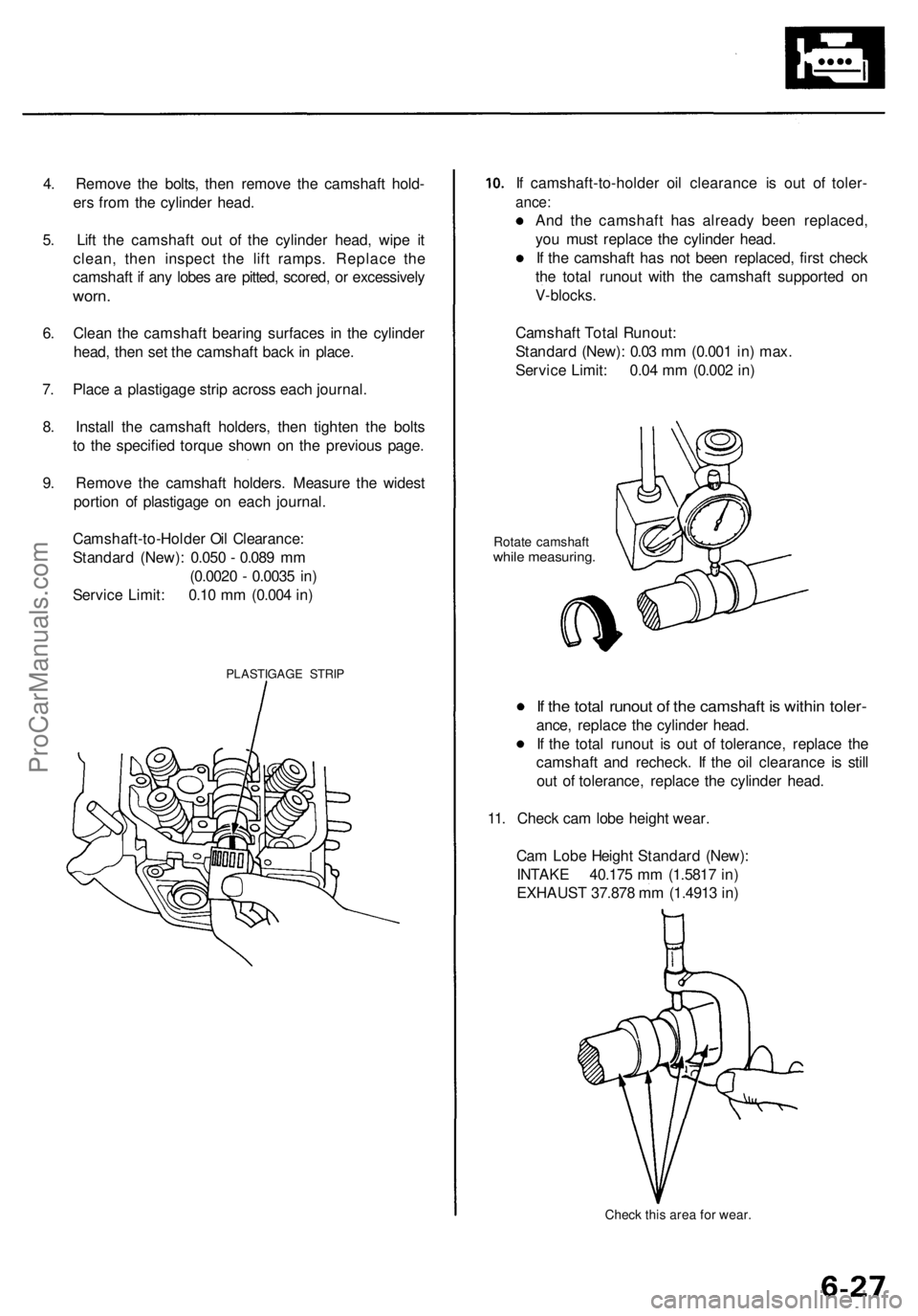
7. Place a plastigage strip across each journal.
8. Install the camshaft holders, then tighten the bolts
to the specified torque shown on the previous page.
9. Remove the camshaft holders. Measure the widest
portion of plastigage on each journal.
PLASTIGAGE STRIP
If camshaft-to-holder oil clearance is out of toler-
ance:
And the camshaft has already been replaced,
you must replace the cylinder head.
If the camshaft has not been replaced, first check
the total runout with the camshaft supported on
V-blocks.
Rotate camshaft
while measuring.
If the total runout of the camshaft is within toler-
ance, replace the cylinder head.
If the total runout is out of tolerance, replace the
camshaft and recheck. If the oil clearance is still
out of tolerance, replace the cylinder head.
11. Check cam lobe height wear.
Check this area for wear.
Cam Lobe Height Standard (New):
INTAKE 40.175 mm (1.5817 in)
EXHAUST 37.878 mm (1.4913 in)
Camshaft Total Runout:
Standard (New): 0.03 mm (0.001 in) max.
Service Limit: 0.04 mm (0.002 in)
Camshaft-to-Holder Oil Clearance:
Standard (New): 0.050 - 0.089 mm
(0.0020 - 0.0035 in)
Service Limit: 0.10 mm (0.004 in)ProCarManuals.com
Page 412 of 1954
Rocker Arms and Shafts
Clearance Inspection
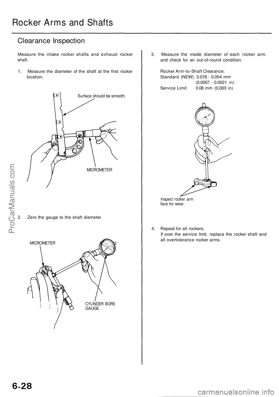
Measure the intake rocker shafts and exhaust rocker
shaft.
1. Measure the diameter of the shaft at the first rocker
location.
Surface should be smooth.
MICROMETER
2. Zero the gauge to the shaft diameter.
MICROMETER
CYLINDER BORE
GAUGE
3. Measure the inside diameter of each rocker arm,
and check for an out-of-round condition.
Rocker Arm-to-Shaft Clearance:
Standard (NEW): 0.018 - 0.054 mm
(0.0007 - 0.0021 in)
Service Limit: 0.08 mm (0.003 in)
Inspect rocker arm
face for wear.
4. Repeat for all rockers.
If over the service limit, replace the rocker shaft and
all overtolerance rocker arms.ProCarManuals.com
Page 413 of 1954
Valves, Valv e Spring s an d Valv e Seal s
Remova l
NOTE: Identif y valve s an d valv e spring s a s the y ar e
remove d s o tha t eac h ite m ca n b e reinstalle d i n it s origi -
nal position .
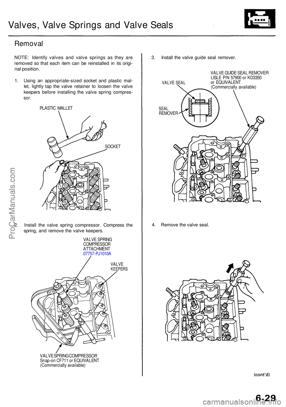
1. Usin g a n appropriate-size d socke t an d plasti c mal -
let , lightl y ta p th e valv e retaine r t o loose n th e valv e
keeper s befor e installin g th e valv e sprin g compres -
sor.
PLASTI C MALLE T
SOCKET
2. Instal l th e valv e sprin g compressor . Compres s th e
spring , an d remov e th e valv e keepers .
VALVE SPRIN GCOMPRESSO RATTACHMENT
0775 7-PJ1010 A
VALVEKEEPER S
VALVE SPRIN G COMPRESSO R
Snap-o n CF71 1 o r EQUIVALEN T
(Commerciall y available )
3. Instal l th e valv e guid e sea l remover .
VALVE SEA L
SEALREMOVE R
VALVE GUID E SEA L REMOVE R
LISL E P/ N 5790 0 o r KD335 0
o r EQUIVALEN T
(Commerciall y available )
4. Remov e th e valv e seal .
ProCarManuals.com
Page 414 of 1954
Valves, Valve Springs and Valve Seal s
Remova l (cont'd )
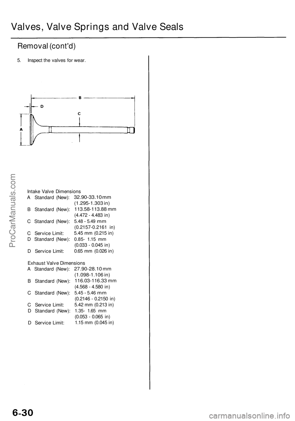
5. Inspec t th e valve s fo r wear .
Intak e Valv e Dimension s
A Standar d (New) :
B Standar d (New) :
C Standar d (New) :
C Servic e Limit :
D Standar d (New) :
D Servic e Limit :
32.90-33.1 0 m m
(1.295-1.30 3 in )
113.58-113.8 8 m m
(4.47 2 - 4.48 3 in )
5.4 8 - 5.4 9 mm
(0.2157-0.216 1 in )
5.4 5 m m (0.21 5 in )
0.85 - 1.1 5 mm
(0.03 3 - 0.04 5 in )
0.6 5 m m (0.02 6 in )
Exhaus t Valv e Dimension s
A Standar d (New) :
B Standar d (New) :
C Standar d (New) :
C Servic e Limit :
D Standar d (New) :
D Servic e Limit :
27.90-28.1 0 m m
(1.098-1.10 6 in )
116.03-116.3 3 m m
(4.56 8 - 4.58 0 in )
5.4 5 - 5.4 6 mm
(0.214 6 - 0.215 0 in )
5.4 2 m m (0.21 3 in )
1.35 - 1.6 5 mm
(0.05 3 - 0.06 5 in )
1.1 5 m m (0.04 5 in )
ProCarManuals.com
Page 415 of 1954
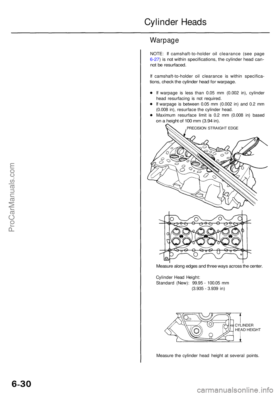
Cylinder Head s
Warpag e
NOTE: I f camshaft-to-holde r oi l clearanc e (se e pag e
6-27) i s no t withi n specifications , th e cylinde r hea d can -
not b e resurfaced .
If camshaft-to-holde r oi l clearanc e i s withi n specifica -
tions, chec k th e cylinde r hea d fo r warpage .
If warpag e i s les s tha n 0.0 5 m m (0.00 2 in) , cylinde r
hea d resurfacin g i s no t required .
I f warpag e i s betwee n 0.0 5 m m (0.00 2 in ) an d 0. 2 m m
(0.00 8 in) , resurfac e th e cylinde r head .
Maximu m resurfac e limi t i s 0. 2 m m (0.00 8 in ) base d
on a heigh t o f 10 0 m m (3.9 4 in) .
Measur e alon g edge s an d thre e way s acros s th e center .
Cylinde r Hea d Height :
Standar d (New) : 99.9 5 - 100.0 5 m m
(3.93 5 - 3.93 9 in )
CYLINDE RHEAD HEIGH T
Measur e th e cylinde r hea d heigh t a t severa l points .
PRECISIO N STRAIGH T EDG E
ProCarManuals.com
Page 416 of 1954
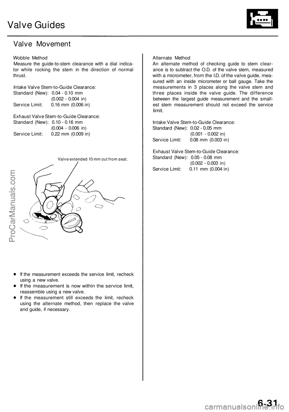
Valve Guides
Valve Movement
Wobble Method
Measure the guide-to-stem clearance with a dial indica-
tor while rocking the stem in the direction of normal
thrust.
Intake Valve Stem-to-Guide Clearance:
Standard (New): 0.04 - 0.10 mm
(0.002 - 0.004 in)
Service Limit: 0.16 mm (0.006 in)
Exhaust Valve Stem-to-Guide Clearance:
Standard (New): 0.10 - 0.16 mm
(0.004 - 0.006 in)
Service Limit: 0.22 mm (0.009 in)
Valve extended 10 mm out from seat.
If the measurement exceeds the service limit, recheck
using a new valve.
If the measurement is now within the service limit,
reassemble using a new valve.
If the measurement still exceeds the limit, recheck
using the alternate method, then replace the valve
and guide, if necessary.
Alternate Method
An alternate method of checking guide to stem clear-
ance is to subtract the O.D. of the valve stem, measured
with a micrometer, from the I.D. of the valve guide, mea-
sured with an inside micrometer or ball gauge. Take the
measurements in 3 places along the valve stem and
three places inside the valve guide. The difference
between the largest guide measurement and the small-
est stem measurement should not exceed the service
limit.
Intake Valve Stem-to-Guide Clearance:
Standard (New): 0.02 - 0.05 mm
(0.001 - 0.002 in)
Service Limit: 0.08 mm (0.003 in)
Exhaust Valve Stem-to-Guide Clearance:
Standard (New): 0.05 - 0.08 mm
(0.002 - 0.003 in)
Service Limit: 0.11 mm (0.004 in)ProCarManuals.com
Page 417 of 1954
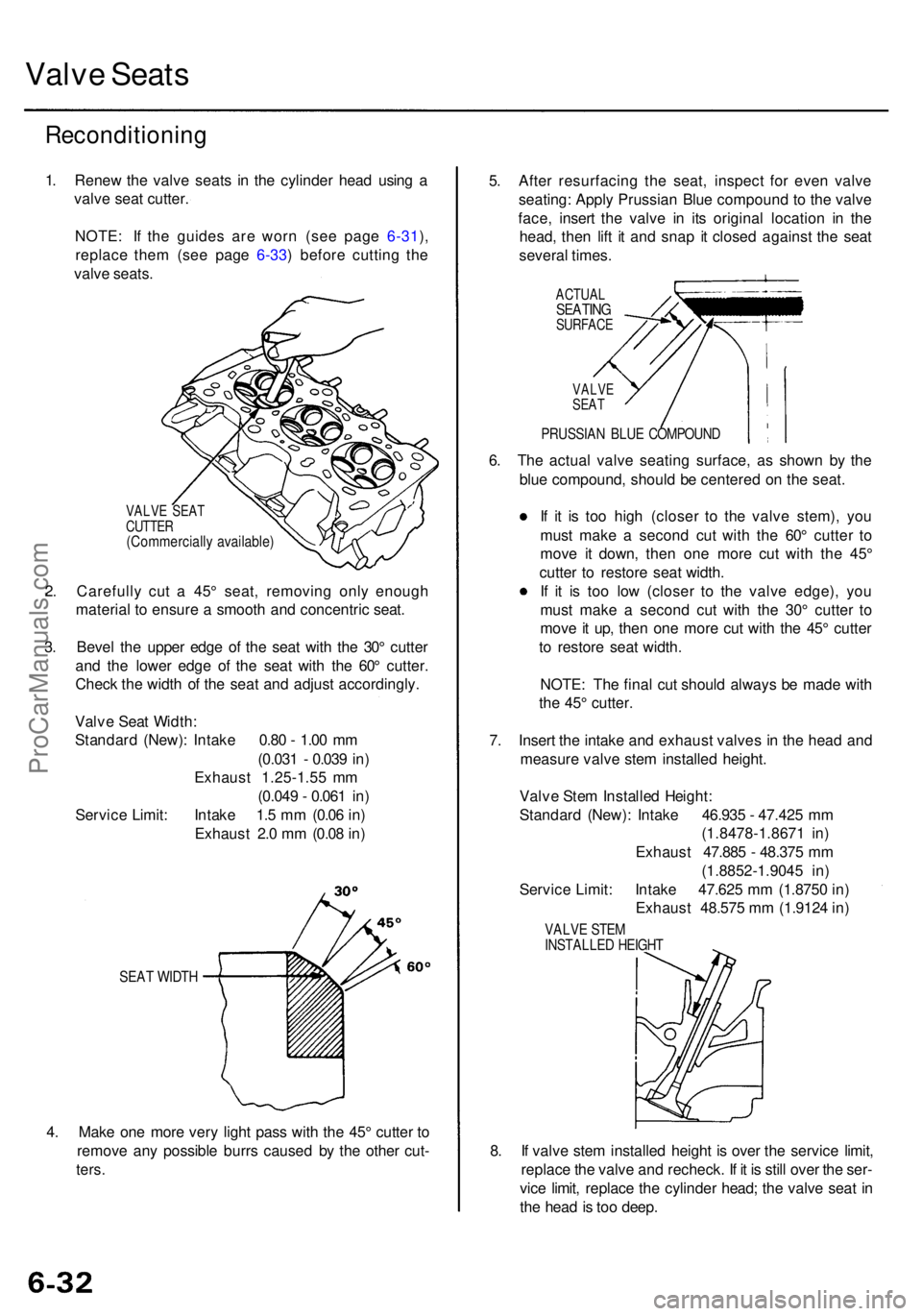
Valve Seat s
Reconditionin g
1. Rene w th e valv e seat s i n th e cylinde r hea d usin g a
valv e sea t cutter .
NOTE : I f th e guide s ar e wor n (se e pag e 6-31 ),
replac e the m (se e pag e 6-33 ) befor e cuttin g th e
valv e seats .
VALV E SEA T
CUTTE R
(Commerciall y available )
2. Carefull y cu t a 45 ° seat , removin g onl y enoug h
materia l t o ensur e a smoot h an d concentri c seat .
3 . Beve l th e uppe r edg e o f th e sea t wit h th e 30 ° cutte r
an d th e lowe r edg e o f th e sea t wit h th e 60 ° cutter .
Chec k th e widt h o f th e sea t an d adjus t accordingly .
SEAT WIDT H
4. Mak e on e mor e ver y ligh t pas s wit h th e 45 ° cutte r t o
remov e an y possibl e burr s cause d b y th e othe r cut -
ters .
5. Afte r resurfacin g th e seat , inspec t fo r eve n valv e
seating : Appl y Prussia n Blu e compoun d t o th e valv e
face , inser t th e valv e i n it s origina l locatio n i n th e
head , the n lif t i t an d sna p i t close d agains t th e sea t
severa l times .
ACTUA LSEATINGSURFAC E
6. Th e actua l valv e seatin g surface , a s show n b y th e
blu e compound , shoul d b e centere d o n th e seat .
I f i t i s to o hig h (close r t o th e valv e stem) , yo u
mus t mak e a secon d cu t wit h th e 60 ° cutte r t o
mov e i t down , the n on e mor e cu t wit h th e 45 °
cutte r t o restor e sea t width .
I f i t i s to o lo w (close r t o th e valv e edge) , yo u
mus t mak e a secon d cu t wit h th e 30 ° cutte r t o
mov e it up , the n on e mor e cu t wit h th e 45 ° cutte r
t o restor e sea t width .
NOTE : Th e fina l cu t shoul d alway s b e mad e wit h
th e 45 ° cutter .
7 . Inser t th e intak e an d exhaus t valve s i n th e hea d an d
measur e valv e ste m installe d height .
8 . I f valv e ste m installe d heigh t i s ove r th e servic e limit ,
replac e th e valv e an d recheck . I f i t i s stil l ove r th e ser -
vic e limit , replac e th e cylinde r head ; th e valv e sea t i n
th e hea d is to o deep .
Valv
e Sea t Width :
Standar d (New) : Intak e 0.8 0 - 1.0 0 m m
(0.03 1 - 0.03 9 in )
Exhaus t 1.25-1.5 5 m m
(0.04 9 - 0.06 1 in )
Servic e Limit : Intak e 1. 5 m m (0.0 6 in )
Exhaus t 2. 0 m m (0.0 8 in ) Valv
e Ste m Installe d Height :
Standar d (New) : Intak e 46.93 5 - 47.42 5 m m
(1.8478-1.867 1 in )
Exhaus t 47.88 5 - 48.37 5 m m
(1.8852-1.904 5 in )
Servic e Limit : Intak e 47.62 5 m m (1.875 0 in )
Exhaus t 48.57 5 m m (1.912 4 in )
VALV E STE MINSTALLE D HEIGH T
VALVESEAT
PRUSSIA N BLU E COMPOUN D
ProCarManuals.com
Page 418 of 1954
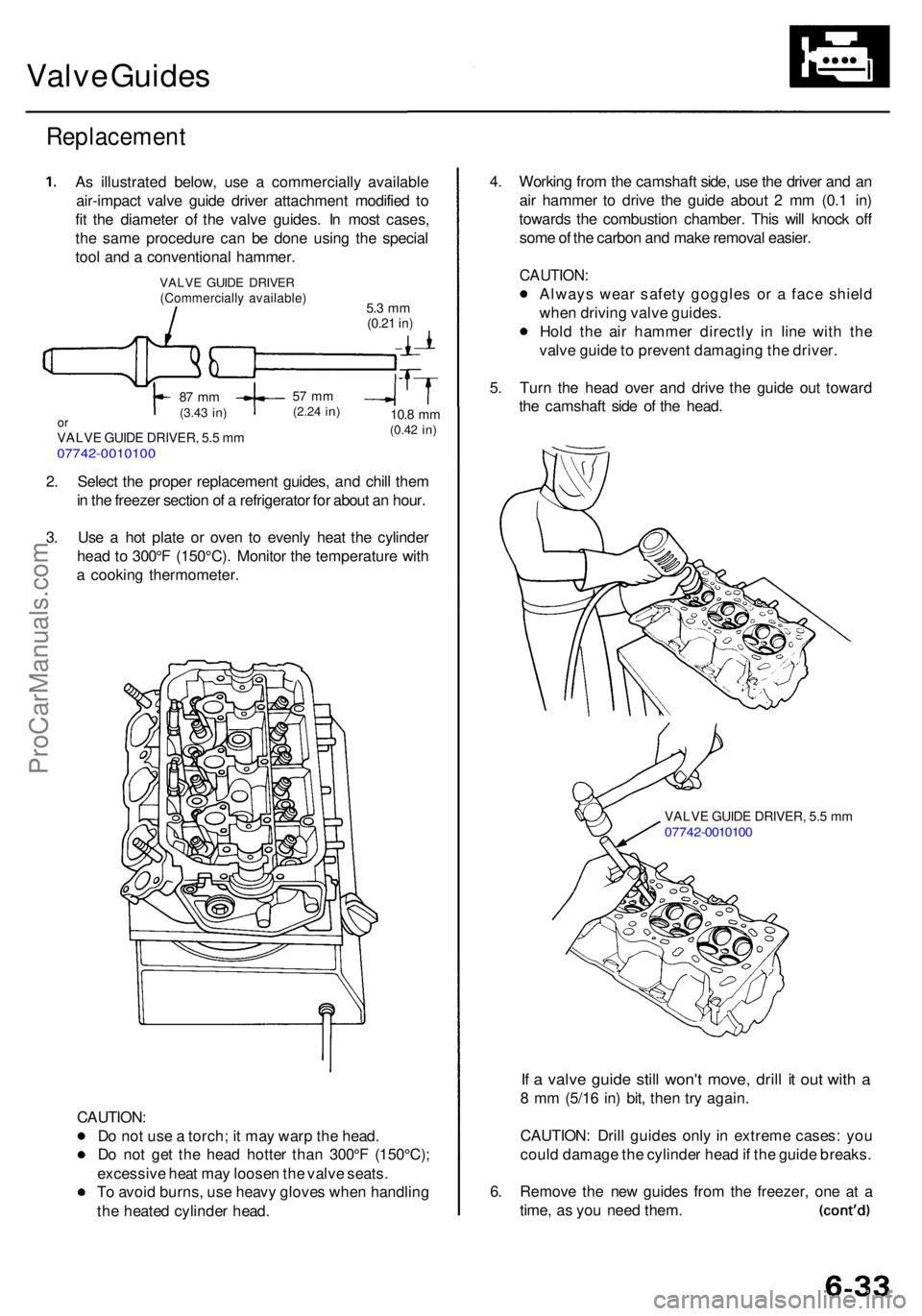
Valve Guide s
Replacemen t
As illustrate d below , us e a commerciall y availabl e
air-impac t valv e guid e drive r attachmen t modifie d t o
fi t th e diamete r o f th e valv e guides . I n mos t cases ,
th e sam e procedur e ca n b e don e usin g th e specia l
too l an d a conventiona l hammer .
2 . Selec t th e prope r replacemen t guides , an d chil l the m
i n th e freeze r sectio n o f a refrigerato r fo r abou t a n hour .
3 . Us e a ho t plat e o r ove n t o evenl y hea t th e cylinde r
hea d t o 300° F (150°C) . Monito r th e temperatur e wit h
a cookin g thermometer .
CAUTION :
D o no t us e a torch ; i t ma y war p th e head .
D o no t ge t th e hea d hotte r tha n 300° F (150°C) ;
excessiv e hea t ma y loose n th e valv e seats .
T o avoi d burns , us e heav y glove s whe n handlin g
th e heate d cylinde r head . 4
. Workin g fro m th e camshaf t side , us e th e drive r an d a n
ai r hamme r t o driv e th e guid e abou t 2 m m (0. 1 in )
toward s th e combustio n chamber . Thi s wil l knoc k of f
som e o f th e carbo n an d mak e remova l easier .
CAUTION :
Always wea r safet y goggle s o r a fac e shiel d
whe n drivin g valv e guides .
Hol d th e ai r hamme r directl y i n lin e wit h th e
valv e guid e to preven t damagin g th e driver .
5 . Tur n th e hea d ove r an d driv e th e guid e ou t towar d
th e camshaf t sid e o f th e head .
VALV E GUID E DRIVER , 5. 5 m m0774 2-001010 0
If a valv e guid e stil l won' t move , dril l i t ou t wit h a
8 m m (5/1 6 in ) bit , the n tr y again .
CAUTION : Dril l guide s onl y in extrem e cases : yo u
coul d damag e th e cylinde r hea d if th e guid e breaks .
6 . Remov e th e ne w guide s fro m th e freezer , on e a t a
time , a s yo u nee d them .
VALV E GUID E DRIVE R(Commerciall y available )5.3 m m(0.2 1 in)
10. 8 mm(0.4 2 in)
57 m m(2.2 4 in)87 m m(3.4 3 in)orVALV E GUID E DRIVER , 5. 5 m m07742-001010 0
ProCarManuals.com
Page 419 of 1954
Valve Guide s
Replacemen t (cont'd )
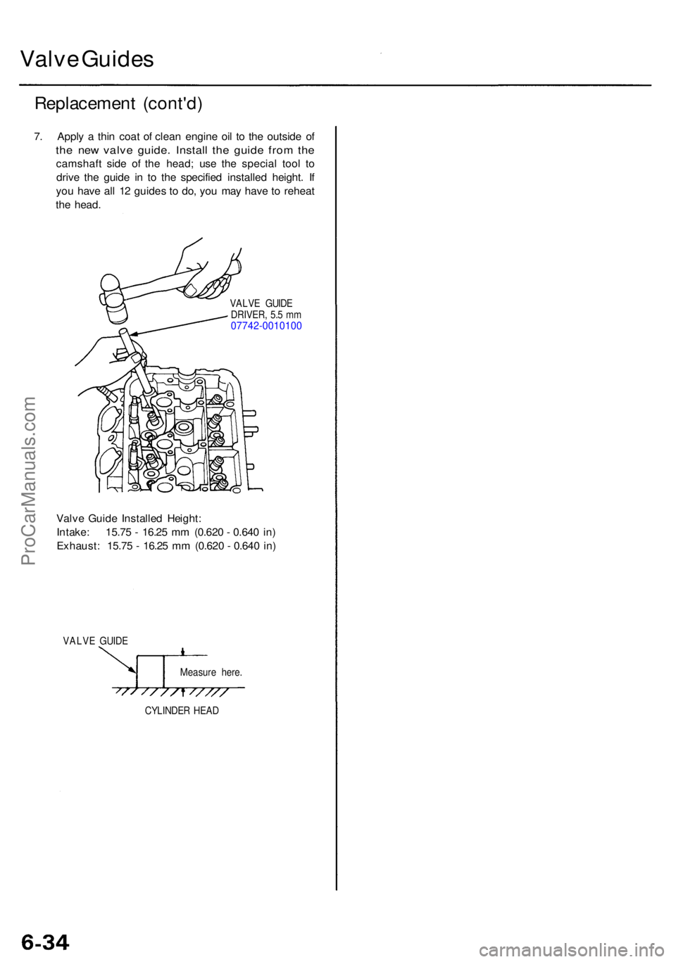
7. Appl y a thi n coa t o f clea n engin e oi l t o th e outsid e o f
the ne w valv e guide . Instal l th e guid e fro m th e
camshaf t sid e o f th e head ; us e th e specia l too l t o
driv e th e guid e i n t o th e specifie d installe d height . I f
yo u hav e al l 1 2 guide s t o do , yo u ma y hav e t o rehea t
th e head .
VALV E GUID E
DRIVER , 5. 5 m m
07742-001010 0
Valve Guid e Installe d Height :
Intake : 15.7 5 - 16.2 5 m m (0.62 0 - 0.64 0 in )
Exhaust : 15.7 5 - 16.2 5 m m (0.62 0 - 0.64 0 in )
VALV E GUID E
Measure here .
CYLINDE R HEA D
ProCarManuals.com
Page 420 of 1954
Valve Guides
Reaming
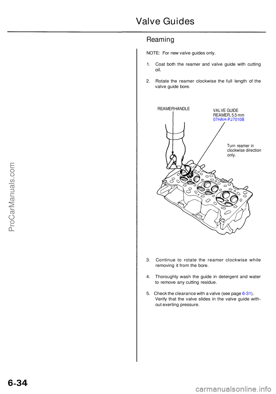
NOTE: Fo r ne w valv e guide s only .
1 . Coa t bot h th e reame r an d valv e guid e wit h cuttin g
oil.
2. Rotat e th e reame r clockwis e th e ful l lengt h o f th e
valv e guid e bore .
REAME R HANDL EVALVE GUID EREAMER , 5. 5 m m
07HAH-PJ7010 B
Tur n reame r i n
clockwis e directio nonly.
3. Continu e t o rotat e th e reame r clockwis e whil e
removin g i t fro m th e bore .
4 . Thoroughl y was h th e guid e i n detergen t an d wate r
t o remov e an y cuttin g residue .
5 . Chec k th e clearanc e wit h a valv e (se e pag e 6-31 ).
Verif y tha t th e valv e slide s i n th e valv e guid e with -
ou t exertin g pressure .
ProCarManuals.com