ACURA RL KA9 1996 Service Repair Manual
Manufacturer: ACURA, Model Year: 1996, Model line: RL KA9, Model: ACURA RL KA9 1996Pages: 1954, PDF Size: 61.44 MB
Page 391 of 1954
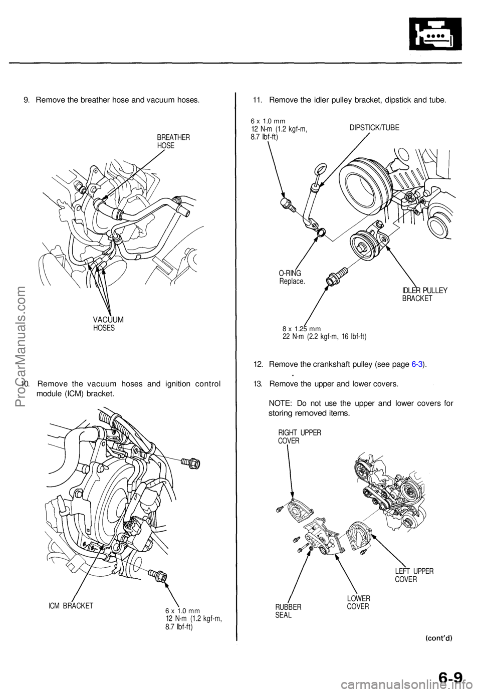
9. Remov e th e breathe r hos e an d vacuu m hoses .
BREATHE R
HOS E
VACUU MHOSES
10. Remov e th e vacuu m hose s an d ignitio n contro l
modul e (ICM ) bracket .
ICM BRACKE T6 x 1. 0 m m12 N- m (1. 2 kgf-m ,8.7 Ibf-ft )
11. Remov e th e idle r pulle y bracket , dipstic k an d tube .
6 x 1. 0 m m12 N- m (1. 2 kgf-m ,8.7 Ibf-ft )
DIPSTICK/TUB E
8 x 1.2 5 mm22 N- m (2. 2 kgf-m , 1 6 Ibf-ft )
12. Remov e th e crankshaf t pulle y (se e pag e 6-3 ).
13 . Remov e th e uppe r an d lowe r covers .
NOTE : D o no t us e th e uppe r an d lowe r cover s fo r
storin g remove d items .
LEFT UPPE R
COVE R
RUBBE R
SEA L LOWE
R
COVE R
RIGH
T UPPE R
COVE R
IDLER PULLE YBRACKE T
O-RIN
G
Replace .
ProCarManuals.com
Page 392 of 1954
Timing Belt and Balancer Belt
Removal (cont'd)
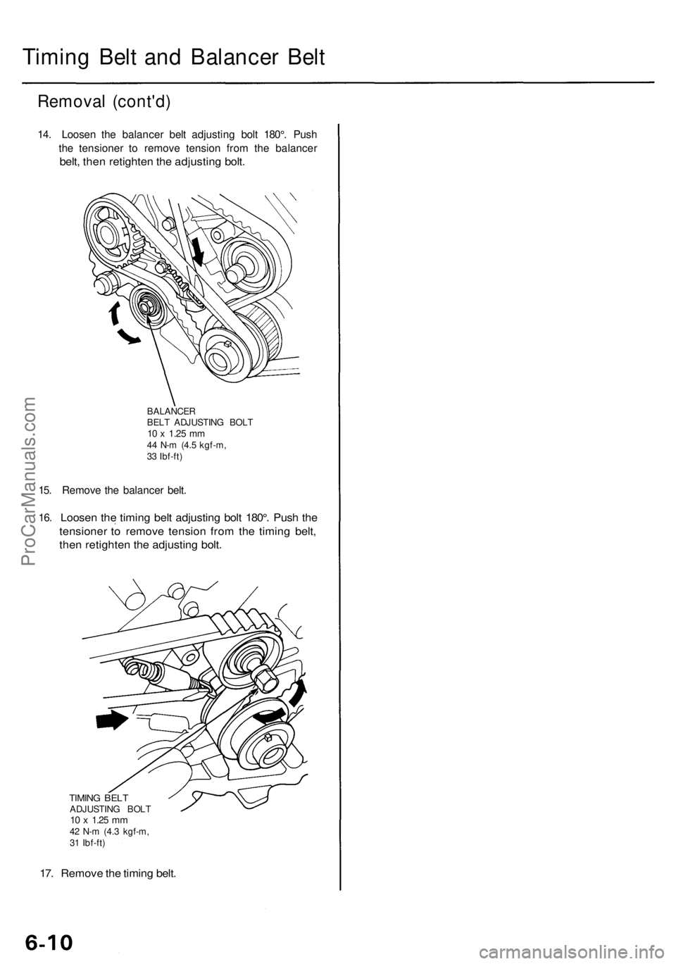
14. Loosen the balancer belt adjusting bolt 180°. Push
the tensioner to remove tension from the balancer
belt, then retighten the adjusting bolt.
BALANCER
BELT ADJUSTING BOLT
10 x
1.25
mm
44 N-m (4.5 kgf-m,
33 Ibf-ft)
15. Remove the balancer belt.
16.
Loosen the timing belt adjusting bolt 180°. Push the
tensioner to remove tension from the timing belt,
then retighten the adjusting bolt.
TIMING BELT
ADJUSTING BOLT
10 x
1.25
mm
42 N-m (4.3 kgf-m,
31 Ibf-ft)
17. Remove the timing belt.ProCarManuals.com
Page 393 of 1954
Timing Bel t an d Balance r Bel t
Installatio n
Install th e timin g bel t an d balance r bel t i n th e revers e
orde r o f removal ; onl y ke y point s ar e describe d here .
CAUTION : D o no t rotat e th e crankshaf t pulle y o r cam -
shaf t pulley s wit h th e timin g bel t removed . Th e piston s
may hi t th e valve s an d caus e damage .
NOTE: Whe n installin g onl y th e balance r belt , g o to ste p
12.
1. Remov e th e spar k plugs .
2. Remov e th e balance r bel t driv e pulle y an d timin g
belt guid e plat e (se e pag e 6-4 ).
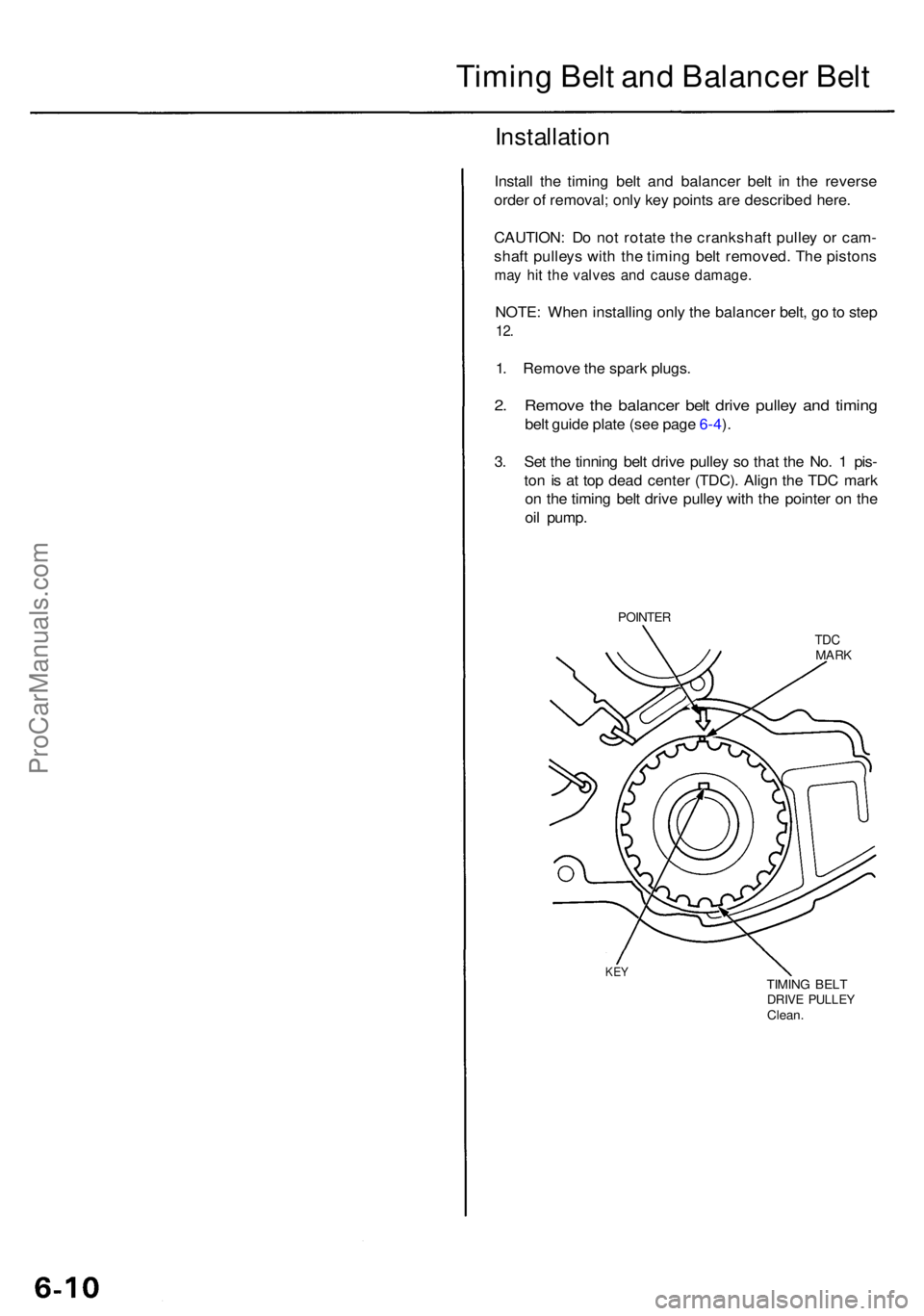
3 . Se t th e tinnin g bel t driv e pulle y s o tha t th e No . 1 pis -
to n is a t to p dea d cente r (TDC) . Alig n th e TD C mar k
o n th e timin g bel t driv e pulle y wit h th e pointe r o n th e
oi l pump .
POINTE R
TDCMAR K
KEYTIMIN G BEL TDRIV E PULLE YClean.
ProCarManuals.com
Page 394 of 1954
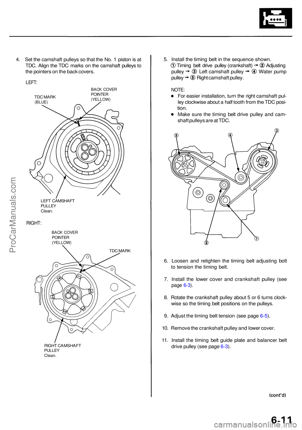
4. Se t th e camshaf t pulley s s o tha t th e No . 1 pisto n is a t
TDC . Alig n th e TD C mark s o n th e camshaf t pulley s to
th e pointer s o n th e bac k covers .
LEFT:
TDC MAR K(BLUE )
BACK COVE RPOINTE R(YELLOW )
LEFT CAMSHAF TPULLEYClean.
RIGHT :
BACK COVE RPOINTE R(YELLOW )
TDC MAR K
RIGH T CAMSHAF T
PULLEYClean.
5. Instal l th e timin g bel t i n th e sequenc e shown .
Timing bel t driv e pulle y (crankshaft ) Adjustin g
pulley Lef t camshaf t pulle y Wate r pum p
pulley Righ t camshaf t pulley .
NOTE :
For easie r installation , tur n th e righ t camshaf t pul -
le y clockwis e abou t a hal f toot h fro m th e TD C posi -
tion.
Mak e sur e th e timin g bel t driv e pulle y an d cam -
shaf t pulley s ar e a t TDC .
6 . Loose n an d retighte n th e timin g bel t adjustin g bol t
t o tensio n th e timin g belt .
7 . Instal l th e lowe r cove r an d crankshaf t pulle y (se e
page 6-3 ).
8 . Rotat e th e crankshaf t pulle y abou t 5 or 6 turn s clock -
wis e s o th e timin g bel t position s o n th e pulleys .
9 . Adjus t th e timin g bel t tensio n (se e pag e 6-5 ).
10 . Remov e th e crankshaf t pulle y an d lowe r cover .
11 . Instal l th e timin g bel t guid e plat e an d balance r bel t
driv e pulle y (se e pag e 6-3 ).
ProCarManuals.com
Page 395 of 1954
Timing Bel t an d Balance r Bel t
Installatio n (cont'd )
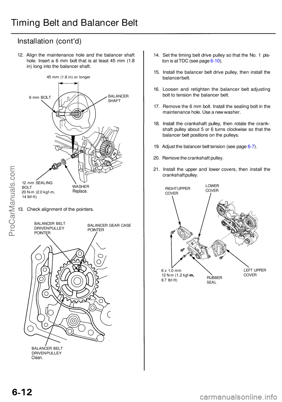
12. Alig n th e maintenanc e hol e an d th e balance r shaf t
hole . Inser t a 6 m m bol t tha t i s a t leas t 4 5 m m (1. 8
in ) lon g int o th e balance r shaft .
6 m m BOL TBALANCE RSHAFT
12 m m SEALIN GBOLT20 N- m (2. 0 kgf-m ,
1 4 Ibf-ft )
WASHE RReplace .
13. Chec k alignmen t o f th e pointers .
BALANCE R BEL TDRIVE N PULLE YPOINTE R
BALANCE R GEA R CAS EPOINTE R
BALANCE R BEL TDRIVE N PULLE YClean.
14. Se t th e timin g bel t driv e pulle y s o tha t th e No . 1 pis -
to n is a t TD C (se e pag e 6-10 ).
15 . Instal l th e balance r bel t driv e pulley , the n instal l th e
balance r belt .
16 . Loose n an d retighte n th e balance r bel t adjustin g
bol t t o tensio n th e balance r belt .
17 . Remov e th e 6 m m bolt . Instal l th e sealin g bol t i n th e
maintenanc e hole . Us e a ne w washer .
18. Instal l th e crankshaf t pulley , the n rotat e th e crank -
shaft pulle y abou t 5 or 6 turn s clockwis e s o tha t th e
balance r bel t position s o n th e pulleys .
19 . Adjus t th e balance r bel t tensio n (se e pag e 6-7 ).
20 . Remov e th e crankshaf t pulley .
21 . Instal l th e uppe r an d lowe r covers , the n instal l th e
crankshaf t pulley .
RIGHT UPPE RCOVE R
LOWE RCOVER
6 x 1. 0 m m12 N- m (1. 2 kgf8.7 Ibf-ft )RUBBE RSEAL
LEFT UPPE RCOVER
45 m m (1. 8 in ) o r longe r
ProCarManuals.com
Page 396 of 1954
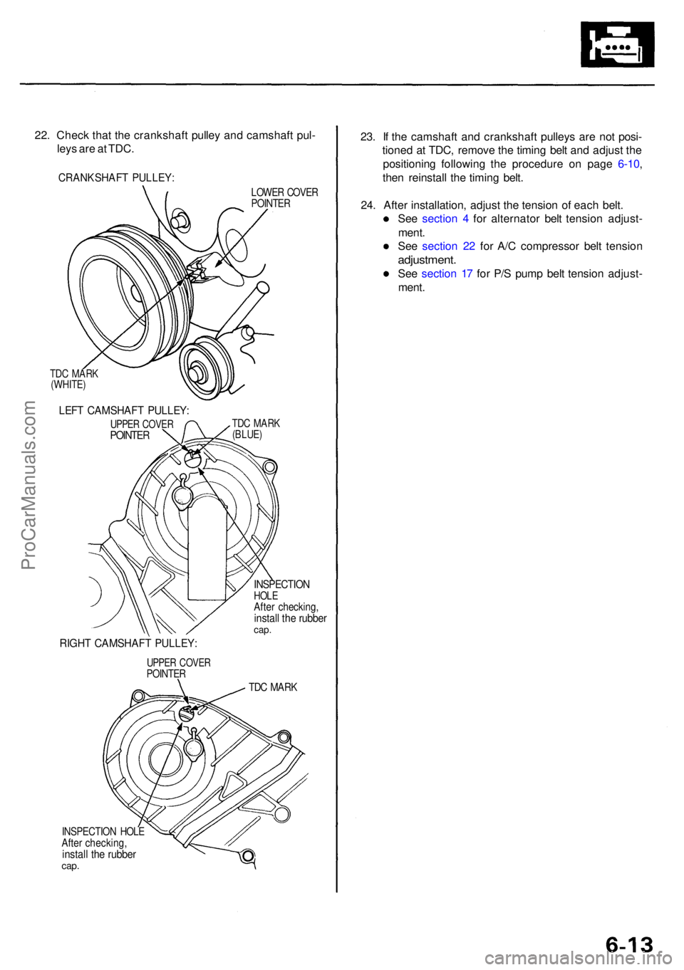
22. Chec k tha t th e crankshaf t pulle y an d camshaf t pul -
ley s ar e a t TDC .
CRANKSHAF T PULLEY :
LOWER COVE RPOINTE R
TDC MAR K(BLUE )
RIGHT CAMSHAF T PULLEY :
UPPER COVE RPOINTE R
INSPECTIO NHOLEAfter checking ,install th e rubbe rcap.
TDC MAR K
INSPECTIO N HOL EAfter checking ,install th e rubbe rcap.
23. I f th e camshaf t an d crankshaf t pulley s ar e no t posi -
tione d a t TDC , remov e th e timin g bel t an d adjus t th e
positionin g followin g th e procedur e o n pag e 6-10 ,
the n reinstal l th e timin g belt .
24 . Afte r installation , adjus t th e tensio n o f eac h belt .
Se e sectio n 4 fo r alternato r bel t tensio n adjust -
ment .
Se e sectio n 2 2 fo r A/ C compresso r bel t tensio n
adjustment .
See sectio n 1 7 fo r P/ S pum p bel t tensio n adjust -
ment .
TDC MAR K(WHITE )
LEFT CAMSHAF T PULLEY :
UPPER COVE RPOINTE R
ProCarManuals.com
Page 397 of 1954
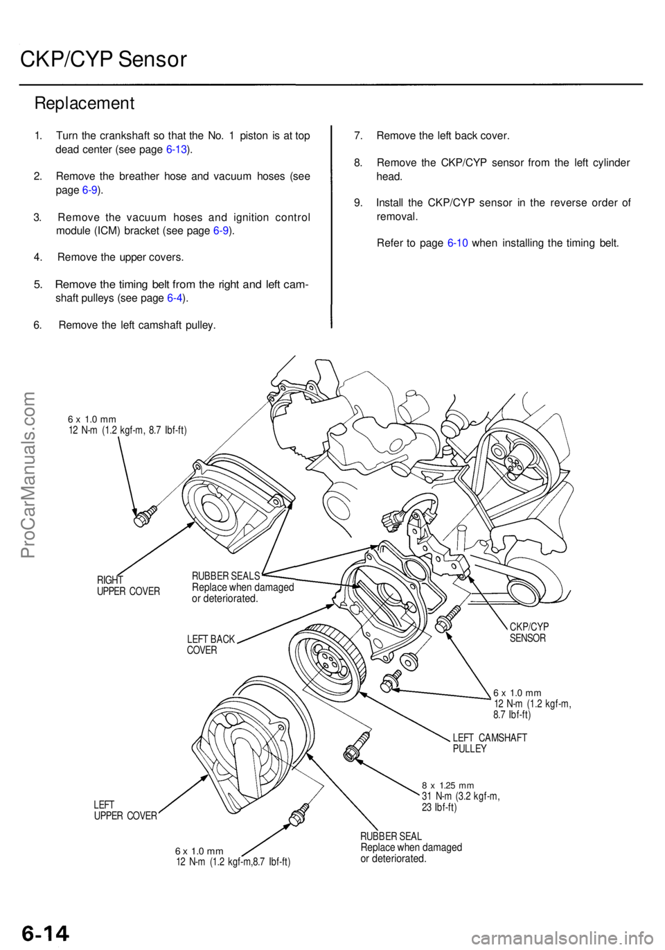
CKP/CYP Senso r
Replacemen t
1. Tur n th e crankshaf t s o tha t th e No . 1 pisto n i s a t to p
dea d cente r (se e pag e 6-13 ).
2 . Remov e th e breathe r hos e an d vacuu m hose s (se e
pag e 6-9 ).
3 . Remov e th e vacuu m hose s an d ignitio n contro l
modul e (ICM ) bracke t (se e pag e 6-9 ).
4 . Remov e th e uppe r covers .
5. Remov e th e timin g bel t fro m th e righ t an d lef t cam -
shaft pulley s (se e pag e 6-4 ).
6 . Remov e th e lef t camshaf t pulley . 7
. Remov e th e lef t bac k cover .
8 . Remov e th e CKP/CY P senso r fro m th e lef t cylinde r
head .
9 . Instal l th e CKP/CY P senso r i n th e revers e orde r o f
removal .
Refe r t o pag e 6-1 0 whe n installin g th e timin g belt .
6 x 1. 0 m m12 N- m (1. 2 kgf-m , 8. 7 Ibf-ft )
RIGH T
UPPE R COVE R
LEF T
UPPE R COVE R
6 x 1. 0 m m12 N- m (1. 2 kgf-m ,
8. 7 Ibf-ft )
LEF T CAMSHAF T
PULLE Y
8 x 1.2 5 mm31 N- m (3. 2 kgf-m ,
2 3 Ibf-ft )
6 x 1. 0 m m12 N- m (1. 2 kgf-m,8. 7 Ibf-ft ) RUBBE
R SEA L
Replac e whe n damage dor deteriorated .
LEFT BAC K
COVE R
RUBBE
R SEAL S
Replac e whe n damage dor deteriorated .
CKP/CYP
SENSO R
ProCarManuals.com
Page 398 of 1954
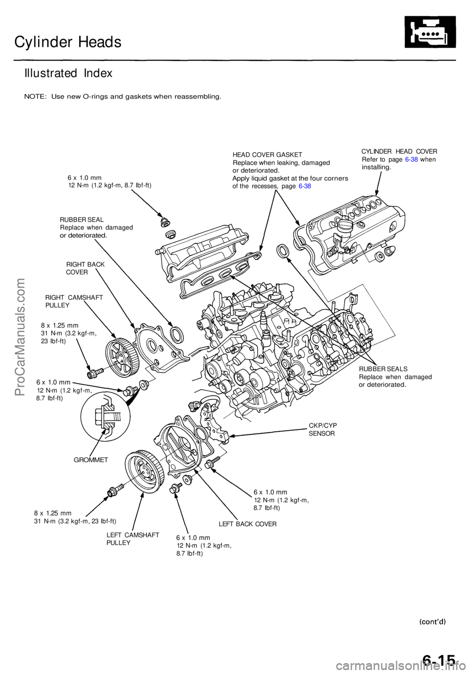
Cylinder Head s
Illustrate d Inde x
NOTE : Us e ne w O-ring s an d gasket s whe n reassembling .
6 x 1. 0 m m12 N- m (1. 2 kgf-m , 8. 7 Ibf-ft )
RUBBE R SEA L
Replac e whe n damage d
or deteriorated .
RIGHT BAC KCOVE R
6 x 1. 0 m m12 N- m (1. 2 kgf-m ,
8. 7 Ibf-ft ) HEA
D COVE R GASKE T
Replace whe n leaking , damage dor deteriorated .Apply liqui d gaske t a t th e fou r corner sof th e recesses , pag e 6-3 8 CYLINDE
R HEA D COVE R
Refe r t o pag e 6-3 8 whe n
installing .
8 x 1.2 5 mm31 N- m (3. 2 kgf-m , 2 3 Ibf-ft ) RUBBE
R SEAL S
Replac e whe n damage d
or deteriorated .
6 x 1. 0 m m12 N- m (1. 2 kgf-m ,
8. 7 Ibf-ft )
LEF T BAC K COVE R
LEF T CAMSHAF T
PULLEY6 x 1. 0 m m12 N- m (1. 2 kgf-m ,
8. 7 Ibf-ft ) CKP/CY
P
SENSO R
RIGH
T CAMSHAF T
PULLEY
8 x 1.2 5 mm31 N- m (3. 2 kgf-m ,
2 3 Ibf-ft )
GROMME T
ProCarManuals.com
Page 399 of 1954
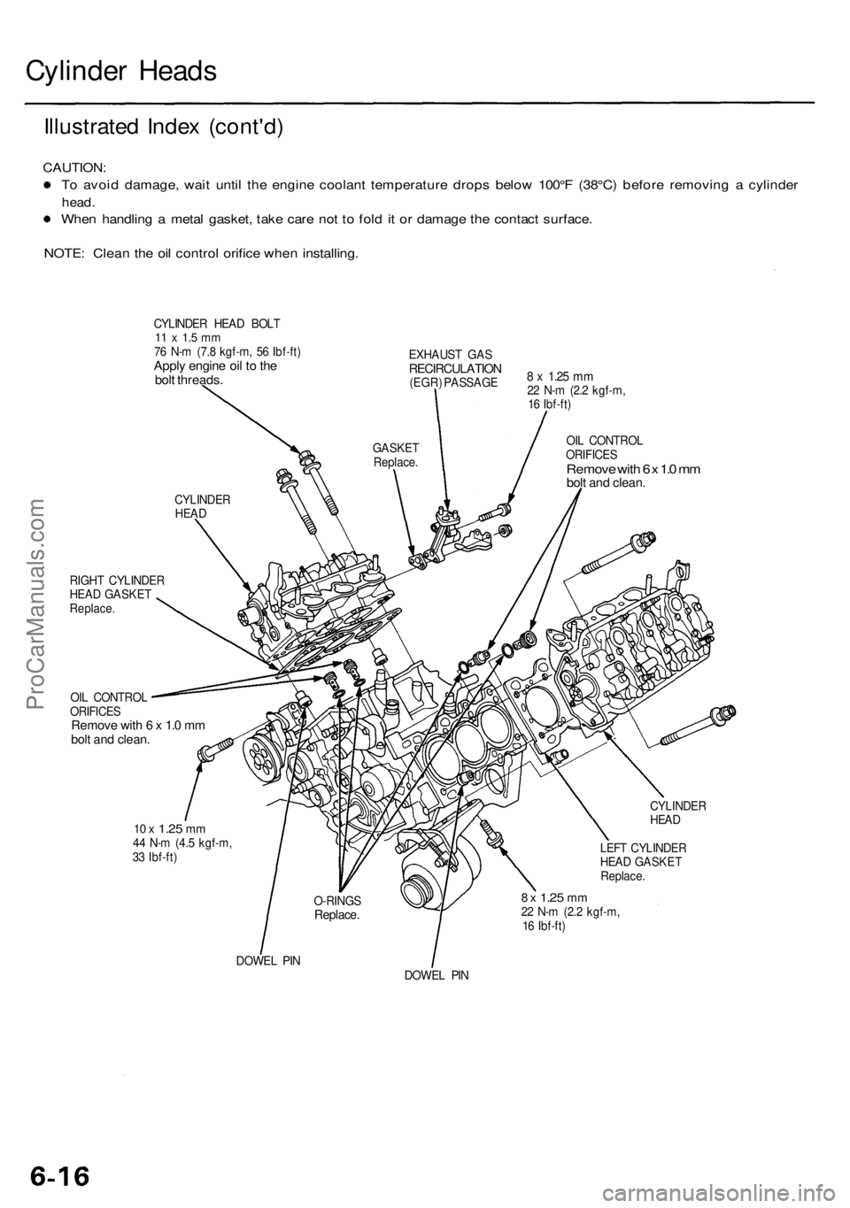
Cylinder Heads
Illustrated Index (cont'd)
CAUTION:
To avoid damage, wait until the engine coolant temperature drops below 100°F (38°C) before removing a cylinder
head.
When handling a metal gasket, take care not to fold it or damage the contact surface.
NOTE: Clean the oil control orifice when installing.
CYLINDER HEAD BOLT
11 x 1.5 mm
76 N-m (7.8 kgf-m, 56 Ibf-ft)
Apply engine oil to the
bolt threads.
EXHAUST GAS
RECIRCULATION
(EGR) PASSAGE
8 x
1.25
mm
22 N-m (2.2 kgf-m,
16 Ibf-ft)
OIL CONTROL
ORIFICES
Remove with 6 x 1.0 mm
bolt and clean.
RIGHT CYLINDER
HEAD GASKET
Replace.
OIL CONTROL
ORIFICES
Remove with 6 x 1.0 mm
bolt and clean.
10 x
1.25
mm
44 N-m (4.5 kgf-m,
33 Ibf-ft)
LEFT CYLINDER
HEAD GASKET
Replace.
8 x
1.25
mm
22 N-m (2.2 kgf-m,
16 Ibf-ft)
DOWEL PIN
DOWEL PIN
GASKET
Replace.
CYLINDER
HEAD
O-RINGS
Replace.
CYLINDER
HEADProCarManuals.com
Page 400 of 1954
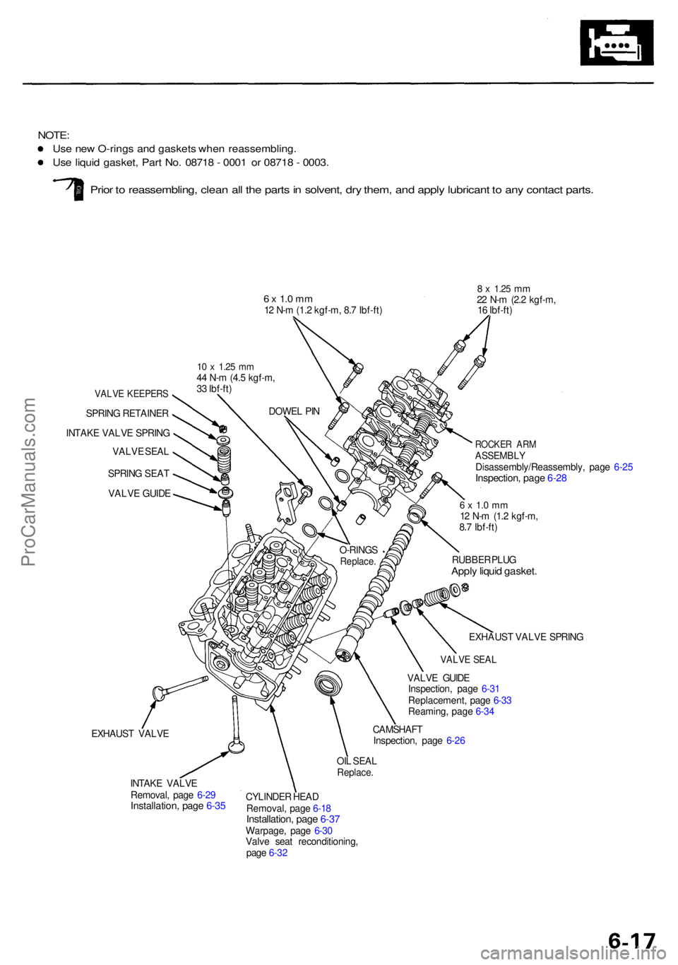
NOTE:
Use ne w O-ring s an d gasket s whe n reassembling .
Use liqui d gasket , Par t No . 0871 8 - 000 1 o r 0871 8 - 0003 .
Prior t o reassembling , clea n al l th e part s in solvent , dr y them , an d appl y lubrican t t o an y contac t parts .
6 x 1. 0 m m12 N- m (1. 2 kgf-m , 8. 7 Ibf-ft )
VALV E KEEPER S
SPRING RETAINE R
INTAK E VALV E SPRIN G
VALV E SEA L
SPRIN G SEA T
VALV E GUID E
EXHAUS T VALV E
8 x 1.2 5 mm22 N- m (2. 2 kgf-m ,
1 6 Ibf-ft )
6 x 1. 0 m m12 N- m (1. 2 kgf-m ,
8. 7 Ibf-ft )
RUBBE R PLU G
Appl y liqui d gasket .
VALVE GUID E
Inspection , pag e 6-3 1
Replacement , pag e 6-3 3
Reaming , pag e 6-3 4
CAMSHAF T
Inspection , pag e 6-2 6
INTAK E VALV E
Removal , pag e 6-2 9
Installation , pag e 6-3 5
OIL SEA LReplace .
CYLINDE R HEA D
Removal , pag e 6-1 8
Installation , pag e 6-3 7Warpage , pag e 6-3 0
Valv e sea t reconditioning ,
pag e 6-3 2 EXHAUS
T VALV E SPRIN G
VALVE SEA L
ROCKE R AR MASSEMBL YDisassembly/Reassembly , pag e 6-2 5Inspection , pag e 6-2 8
DOWE L PI N
10 x 1.2 5 mm44 N- m (4. 5 kgf-m ,
3 3 Ibf-ft )
O-RINGS
Replace .
ProCarManuals.com