ACURA RL KA9 1996 Service Repair Manual
Manufacturer: ACURA, Model Year: 1996, Model line: RL KA9, Model: ACURA RL KA9 1996Pages: 1954, PDF Size: 61.44 MB
Page 371 of 1954
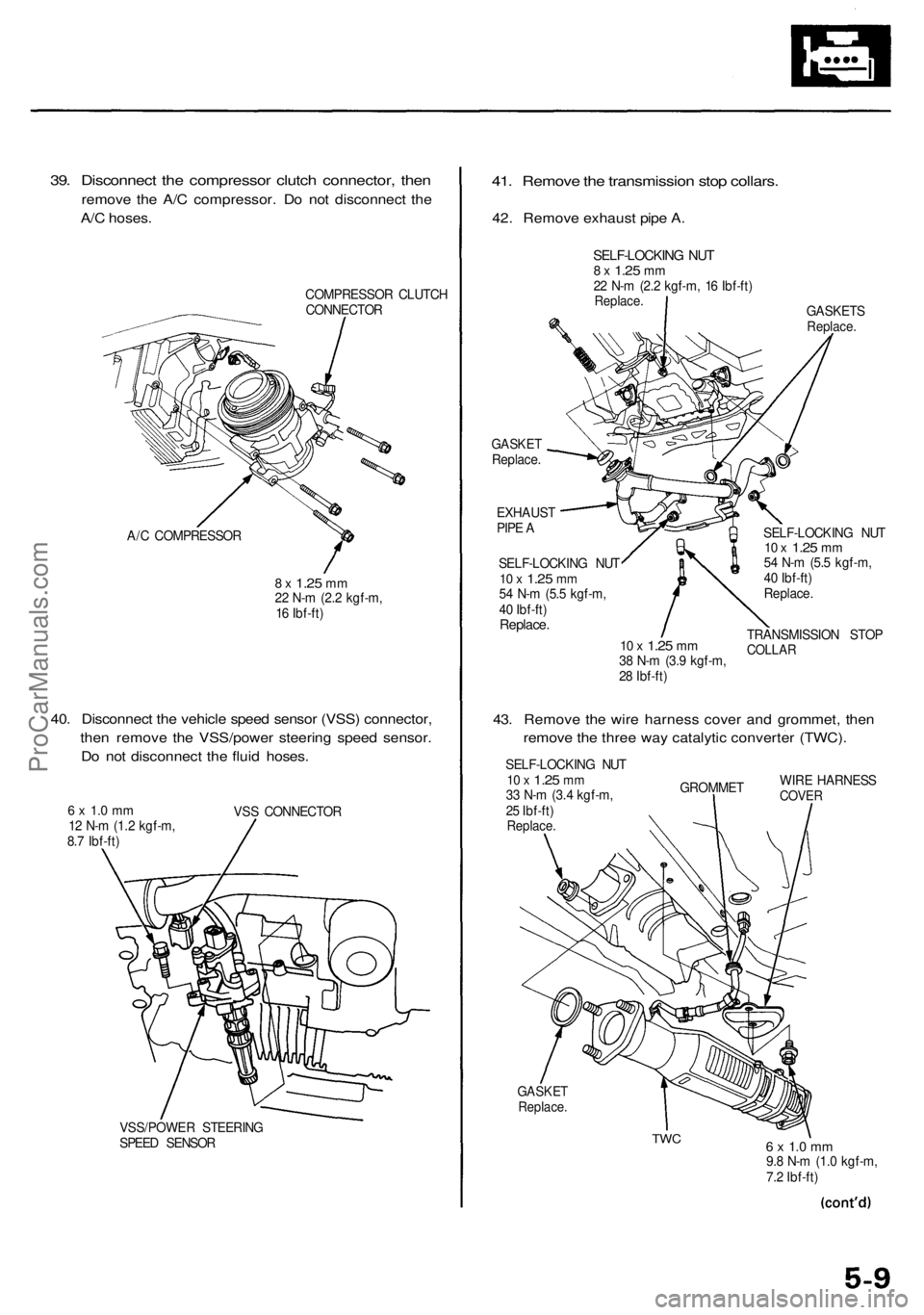
39. Disconnect the compressor clutch connector, then
remove the A/C compressor. Do not disconnect the
A/C hoses.
COMPRESSOR CLUTCH
CONNECTOR
A/C COMPRESSOR
8 x
1.25
mm
22 N-m (2.2 kgf-m,
16 Ibf-ft)
40. Disconnect the vehicle speed sensor (VSS) connector,
then remove the VSS/power steering speed sensor.
Do not disconnect the fluid hoses.
6 x 1.0 mm
12 N-m (1.2 kgf-m,
8.7 Ibf-ft)
VSS CONNECTOR
VSS/POWER STEERING
SPEED SENSOR
41. Remove the transmission stop collars.
42. Remove exhaust pipe A.
GASKETS
Replace.
GASKET
Replace.
EXHAUST
PIPE A
SELF-LOCKING NUT
10 x
1.25
mm
54 N-m (5.5 kgf-m,
40 Ibf-ft)
Replace.
10 x
1.25
mm
38 N-m (3.9 kgf-m,
28 Ibf-ft)
SELF-LOCKING NUT
10 x
1.25
mm
54 N-m (5.5 kgf-m,
40 Ibf-ft)
Replace.
TRANSMISSION STOP
COLLAR
43. Remove the wire harness cover and grommet, then
remove the three way catalytic converter (TWC).
SELF-LOCKING NUT
10 x
1.25
mm
33 N-m (3.4 kgf-m,
25 Ibf-ft)
Replace.
GROMMET
WIRE HARNESS
COVER
GASKET
Replace.
TWC
6 x 1.0 mm
9.8 N-m (1.0 kgf-m,
7.2 Ibf-ft)
SELF-LOCKING NUT
8 x
1.25
mm
22 N-m (2.2 kgf-m, 16 Ibf-ft)
Replace.ProCarManuals.com
Page 372 of 1954
Engine Removal/Installatio n
Removal (cont'd )
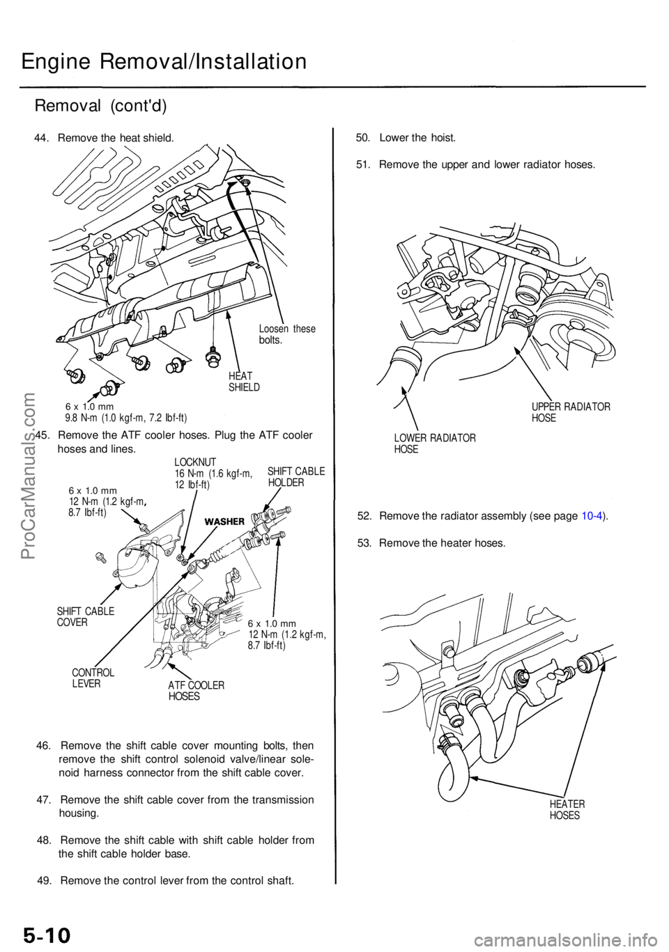
44. Remov e th e hea t shield .
Loosen thes ebolts.
HEATSHIEL D
6 x 1. 0 m m9.8 N- m (1. 0 kgf-m , 7. 2 Ibf-ft )
45. Remov e th e AT F coole r hoses . Plu g th e AT F coole r
hose s an d lines .
6 x 1. 0 m m12 N- m (1. 2 kgf- m
8. 7 Ibf-ft ) LOCKNU
T
1 6 N- m (1. 6 kgf-m ,
1 2 Ibf-ft ) SHIF
T CABL E
HOLDE R
SHIF T CABL E
COVE R
CONTRO L
LEVER
6 x 1. 0 m m12 N- m (1. 2 kgf-m ,
8. 7 Ibf-ft )
AT F COOLE R
HOSES
46. Remov e th e shif t cabl e cove r mountin g bolts , the n
remov e th e shif t contro l solenoi d valve/linea r sole -
noi d harnes s connecto r fro m th e shif t cabl e cover .
47 . Remov e th e shif t cabl e cove r fro m th e transmissio n
housing .
48 . Remov e th e shif t cabl e wit h shif t cabl e holde r fro m
th e shif t cabl e holde r base .
49 . Remov e th e contro l leve r fro m th e contro l shaft . 50
. Lowe r th e hoist .
51 . Remov e th e uppe r an d lowe r radiato r hoses .
UPPER RADIATO R
HOS E
LOWE R RADIATO R
HOS E
52. Remov e th e radiato r assembl y (se e pag e 10-4 ).
53 . Remov e th e heate r hoses .
HEATE RHOSES
ProCarManuals.com
Page 373 of 1954
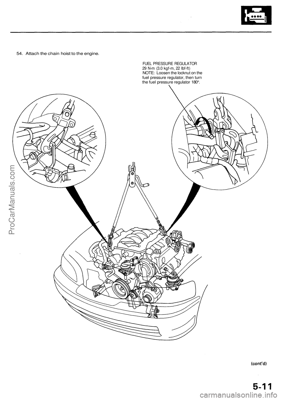
54. Attach the chain hoist to the engine.
FUEL PRESSURE REGULATOR
29 N-m (3.0 kgf-m, 22 Ibf-ft)
NOTE: Loosen the locknut on the
fuel pressure regulator, then turn
the fuel pressure regulator 180°.ProCarManuals.com
Page 374 of 1954
Engine Removal/Installatio n
Removal (cont'd )
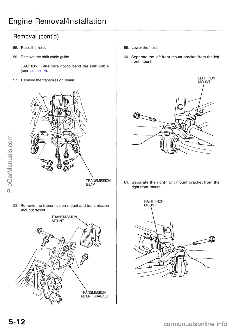
55. Rais e th e hoist .
56. Remov e th e shif t cabl e guide .
CAUTION : Tak e car e no t t o ben d th e shif t cabl e
(see sectio n 14 ).
57 . Remov e th e transmissio n beam .
TRANSMISSIO NBEAM
58. Remov e th e transmissio n moun t an d transmissio n
moun t bracket .
TRANSMISSION ,MOUNT
TRANSMISSIO NMOUNT BRACKE T
59. Lowe r th e hoist .
60 . Separat e th e lef t fron t moun t bracke t fro m th e lef t
fron t mount .
LEFT FRON TMOUNT
61. Separat e th e righ t fron t moun t bracke t fro m th e
righ t fron t mount .
RIGHT FRON TMOUNT
ProCarManuals.com
Page 375 of 1954
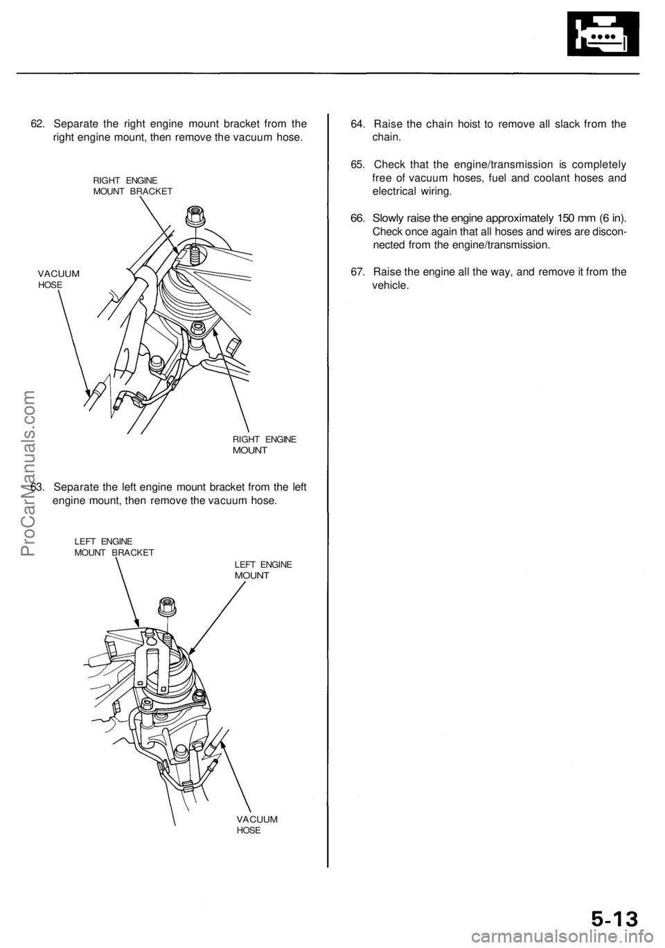
62. Separate the right engine mount bracket from the
right engine mount, then remove the vacuum hose.
RIGHT ENGINE
MOUNT BRACKET
VACUUM
HOSE
RIGHT ENGINE
MOUNT
63. Separate the left engine mount bracket from the left
engine mount, then remove the vacuum hose.
LEFT ENGINE
MOUNT BRACKET
LEFT ENGINE
MOUNT
VACUUM
HOSE
64. Raise the chain hoist to remove all slack from the
chain.
65. Check that the engine/transmission is completely
free of vacuum hoses, fuel and coolant hoses and
electrical wiring.
66. Slowly raise the engine approximately 150 mm (6 in).
Check once again that all hoses and wires are discon-
nected from the engine/transmission.
67. Raise the engine all the way, and remove it from the
vehicle.ProCarManuals.com
Page 376 of 1954
Engine Removal/Installatio n
Installation
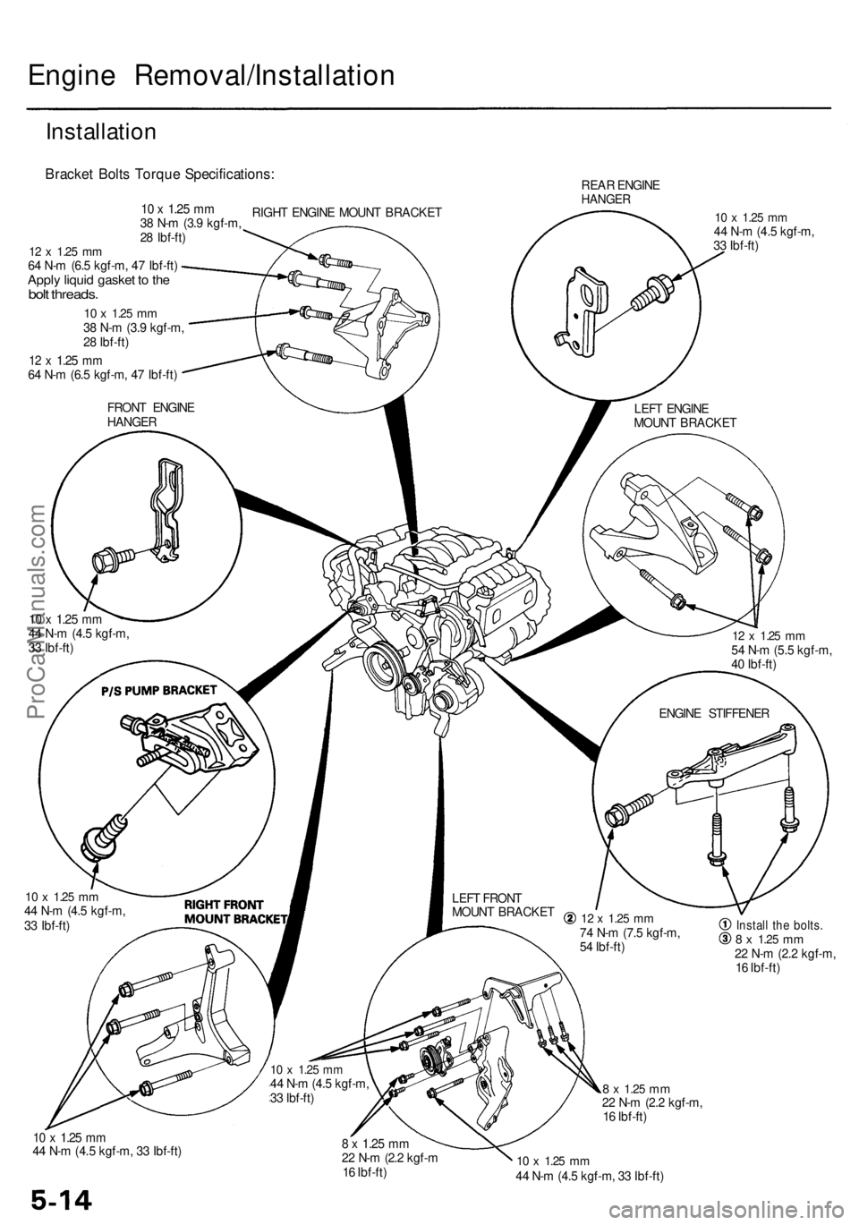
Bracket Bolt s Torqu e Specifications :
RIGHT ENGIN E MOUN T BRACKE T REA
R ENGIN EHANGE R
10 x 1.2 5 mm44 N- m (4. 5 kgf-m ,
3 3 Ibf-ft )
10 x 1.2 5 mm44 N- m (4. 5 kgf-m ,
3 3 Ibf-ft )
10 x 1.2 5 mm44 N- m (4. 5 kgf-m ,
3 3 Ibf-ft )Instal l th e bolts .8 x 1.2 5 mm22 N- m (2. 2 kgf-m ,
1 6 Ibf-ft )
8 x 1.2 5 mm22 N- m (2. 2 kgf-m ,
1 6 Ibf-ft )
10 x 1.2 5 mm44 N- m (4. 5 kgf-m , 3 3 Ibf-ft )8 x 1.2 5 mm22 N- m (2. 2 kgf- m
1 6 Ibf-ft )10 x 1.2 5 mm44 N- m (4. 5 kgf-m , 3 3 Ibf-ft )
12 x 1.2 5 mm74 N- m (7. 5 kgf-m ,
5 4 Ibf-ft )
LEF
T FRON T
MOUN T BRACKE T ENGIN
E STIFFENE R
12 x 1.2 5 mm54 N- m (5. 5 kgf-m ,
4 0 Ibf-ft )
LEF
T ENGIN E
MOUN T BRACKE T
FRON
T ENGIN E
HANGE R
12 x 1.2 5 mm64 N- m (6. 5 kgf-m , 4 7 Ibf-ft )
10 x 1.2 5 mm38 N- m (3. 9 kgf-m ,
2 8 Ibf-ft )
12 x 1.2 5 mm64 N- m (6. 5 kgf-m , 4 7 Ibf-ft )Apply liqui d gaske t t o th ebol t threads .
10 x 1.2 5 mm38 N- m (3. 9 kgf-m ,
2 8 Ibf-ft )
10 x 1.2 5 m m44 N- m (4. 5 kgf-m ,
3 3 Ibf-ft )
ProCarManuals.com
Page 377 of 1954
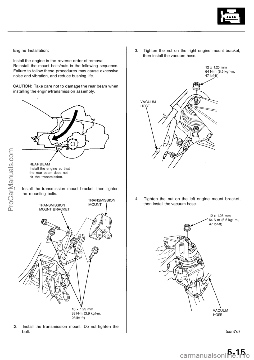
Engine Installation :
Instal l th e engin e in th e revers e orde r o f removal .
Reinstal l th e moun t bolts/nut s i n th e followin g sequence .
Failur e t o follo w thes e procedure s ma y caus e excessiv e
nois e an d vibration , an d reduc e bushin g life .
CAUTION : Tak e car e no t t o damag e th e rea r bea m whe n
installin g th e engine/transmissio n assembly .
REAR BEA M
Instal l th e engin e s o tha t
th e rea r bea m doe s no t
hi t th e transmission .
1. Instal l th e transmissio n moun t bracket , the n tighte n
th e mountin g bolts .
TRANSMISSIO N
MOUN T BRACKE T
TRANSMISSIO NMOUNT
2. Instal l th e transmissio n mount . D o no t tighte n th e
bolt .
3. Tighte n th e nu t o n th e righ t engin e moun t bracket ,
the n instal l th e vacuu m hose .
12 x 1.2 5 mm64 N- m (6. 5 kgf-m ,
4 7 Ibf-ft )
VACUU M
HOSE
4. Tighte n th e nu t o n th e lef t engin e moun t bracket ,
the n instal l th e vacuu m hose .
12 x 1.2 5 mm64 N- m (6. 5 kgf-m ,
4 7 Ibf-ft )
VACUU M
HOSE
10 x 1.2 5 mm38 N- m (3. 9 kgf-m ,
2 8 Ibf-ft )
ProCarManuals.com
Page 378 of 1954
Engine Removal/Installatio n
Installation (cont'd )
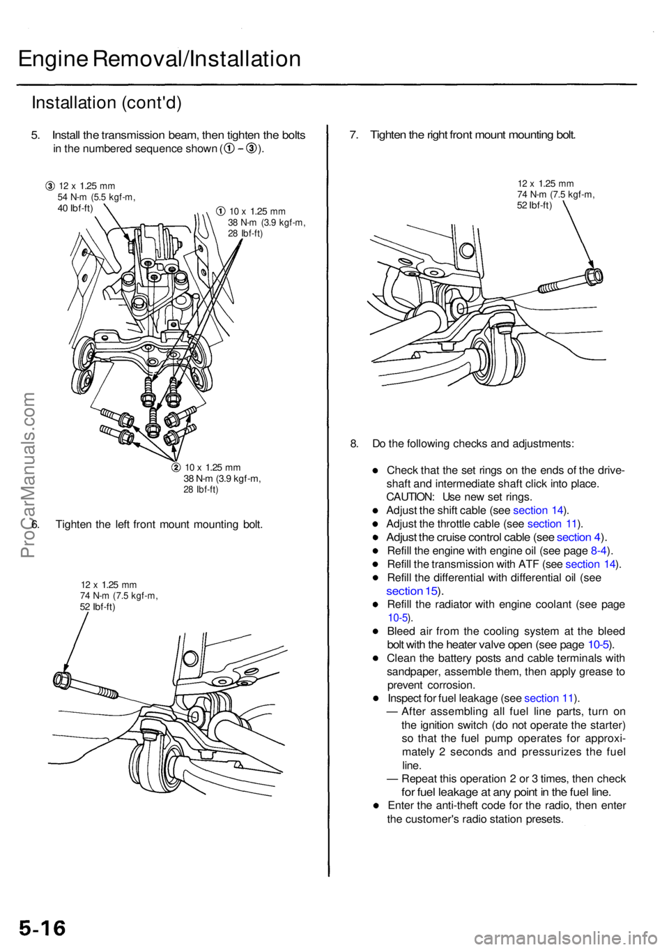
5. Instal l th e transmissio n beam , the n tighte n th e bolt s
in th e numbere d sequenc e show n ( ) .
12 x 1.2 5 mm54 N- m (5. 5 kgf-m ,40 Ibf-ft )10 x 1.2 5 mm38 N- m (3. 9 kgf-m ,28 Ibf-ft )
10 x 1.2 5 mm38 N- m (3. 9 kgf-m ,28 Ibf-ft )
6. Tighte n th e lef t fron t moun t mountin g bolt .
12 x 1.2 5 mm74 N- m (7. 5 kgf-m ,52 Ibf-ft )
7. Tighte n th e righ t fron t moun t mountin g bolt .
12 x 1.2 5 mm74 N- m (7. 5 kgf-m ,52 Ibf-ft )
8. D o th e followin g check s an d adjustments :
Chec k tha t th e se t ring s o n th e end s o f th e drive -
shaf t an d intermediat e shaf t clic k int o place .
CAUTION : Us e ne w se t rings .
Adjus t th e shif t cabl e (se e sectio n 14 ).
Adjus t th e throttl e cabl e (se e sectio n 11 ).
Adjus t th e cruis e contro l cabl e (se e sectio n 4 ).
Refil l th e engin e wit h engin e oi l (se e pag e 8-4 ).
Refil l th e transmissio n wit h AT F (se e sectio n 14 ).
Refil l th e differentia l wit h differentia l oi l (se e
sectio n 15 ).
Refil l th e radiato r wit h engin e coolan t (se e pag e
10-5).
Blee d ai r fro m th e coolin g syste m a t th e blee d
bolt wit h th e heate r valv e ope n (se e pag e 10-5 ).
Clea n th e batter y post s an d cabl e terminal s wit h
sandpaper , assembl e them , the n appl y greas e to
preven t corrosion .
Inspec t fo r fue l leakag e (se e sectio n 11 ).
— Afte r assemblin g al l fue l lin e parts , tur n o n
th e ignitio n switc h (d o no t operat e th e starter )
s o tha t th e fue l pum p operate s fo r approxi -
matel y 2 second s an d pressurize s th e fue l
line .
— Repea t thi s operatio n 2 or 3 times , the n chec k
for fue l leakag e a t an y poin t i n th e fue l line .
Ente r th e anti-thef t cod e fo r th e radio , the n ente r
th e customer' s radi o statio n presets .
ProCarManuals.com
Page 379 of 1954
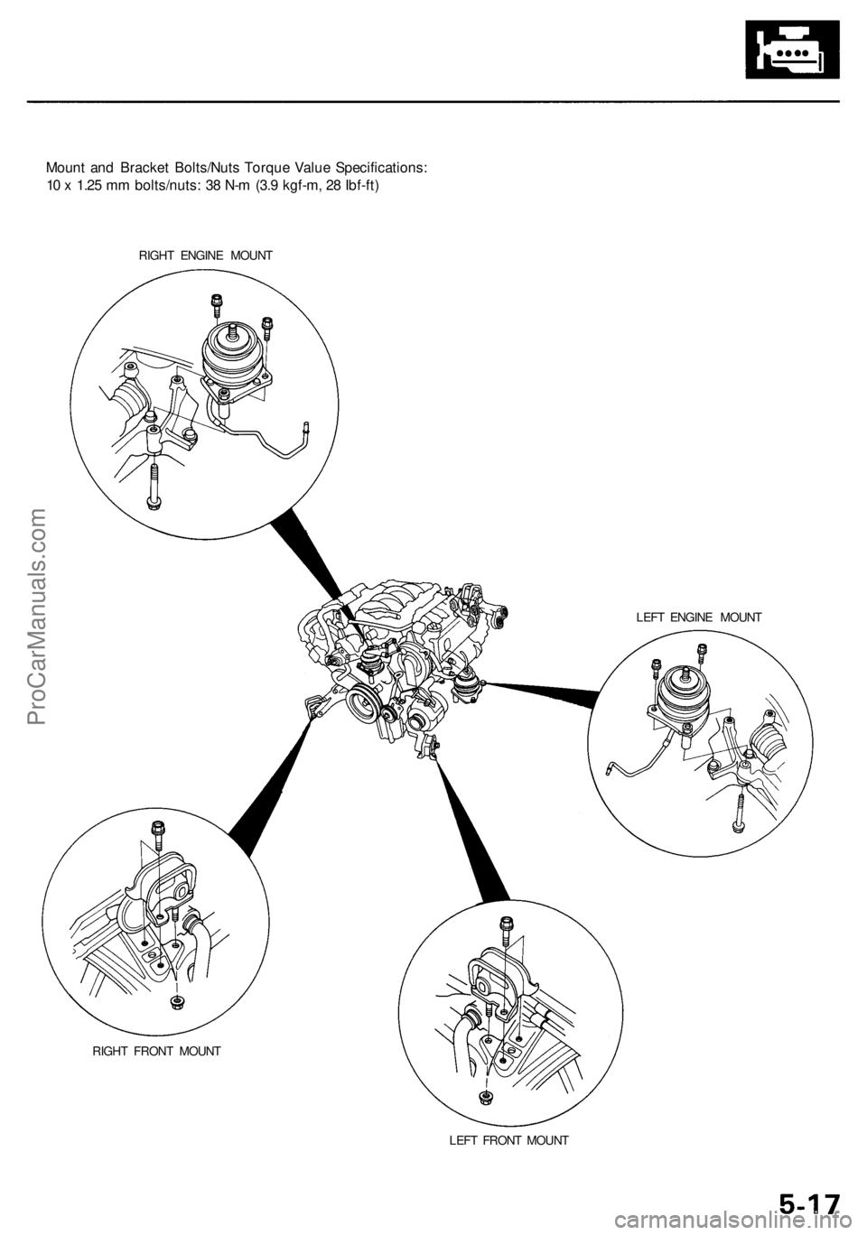
Mount and Bracket Bolts/Nuts Torque Value Specifications:
10 x 1.25 mm bolts/nuts: 38 N-m (3.9 kgf-m, 28 Ibf-ft)
RIGHT ENGINE MOUNT
LEFT ENGINE MOUNT
RIGHT FRONT MOUNT
LEFT FRONT MOUNTProCarManuals.com
Page 380 of 1954
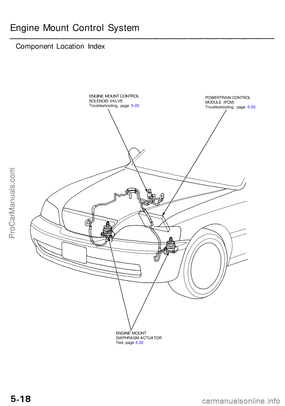
Engine Moun t Contro l Syste m
Componen t Locatio n Inde x
ENGIN E MOUN T CONTRO LSOLENOI D VALV E
Troubleshooting , pag e 5-2 0 POWERTRAI
N CONTRO L
MODUL E (PCM )
Troubleshooting , pag e 5-2 0
ENGIN E MOUN TDIAPHRAG M ACTUATO R
Test , pag e 5-2 2
ProCarManuals.com