ACURA TL 1995 Service Repair Manual
Manufacturer: ACURA, Model Year: 1995, Model line: TL, Model: ACURA TL 1995Pages: 1771, PDF Size: 62.49 MB
Page 1461 of 1771
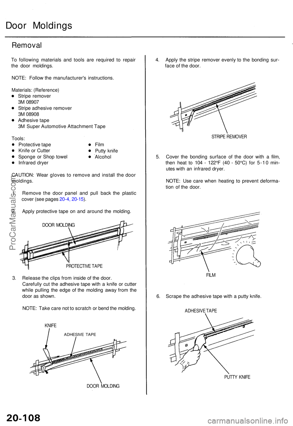
Door Molding s
Removal
To followin g material s an d tool s ar e require d t o repai r
th e doo r moldings .
NOTE : Follo w th e manufacturer' s instructions .
Materials: (Reference )
Stripe remove r
3 M 0890 7
Strip e adhesiv e remove r
3 M 0890 8
Adhesiv e tap e
3 M Supe r Automotiv e Attachmen t Tap e
Tools :
Protectiv e tap e
Knif e o r Cutte r
Spong e o r Sho p towe l
Infrare d drye r Fil
m
Putt y knif e
Alcoho l
CAUTION : Wea r glove s t o remov e an d instal l th e doo r
moldings .
1 . Remov e th e doo r pane l an d pul l bac k th e plasti c
cove r (se e page s 20-4 , 20-15 ).
2 . Appl y protectiv e tap e o n an d aroun d th e molding .
DOOR MOLDIN G
PROTECTIV E TAP E
3. Releas e th e clip s fro m insid e o f th e door .
Carefull y cu t th e adhesiv e tap e wit h a knif e o r cutte r
whil e pullin g th e edg e o f th e moldin g awa y fro m th e
doo r a s shown .
NOTE : Tak e car e no t t o scratc h o r ben d th e molding .
KNIFE
DOO R MOLDIN G
4. Appl y th e strip e remove r evenl y t o th e bondin g sur -
fac e o f th e door .
STRIP E REMOVE R
5. Cove r th e bondin g surfac e o f th e doo r wit h a film ,
the n hea t t o 10 4 - 122° F (4 0 - 50°C ) fo r 5-1 0 min -
ute s wit h a n infrare d dryer .
NOTE : Us e car e whe n heatin g t o preven t deforma -
tio n o f th e door .
FILM
6. Scrap e th e adhesiv e tap e wit h a putt y knife .
ADHESIV E TAP E
PUTT Y KNIF E
ADHESIV E TAP E
ProCarManuals.com
Page 1462 of 1771
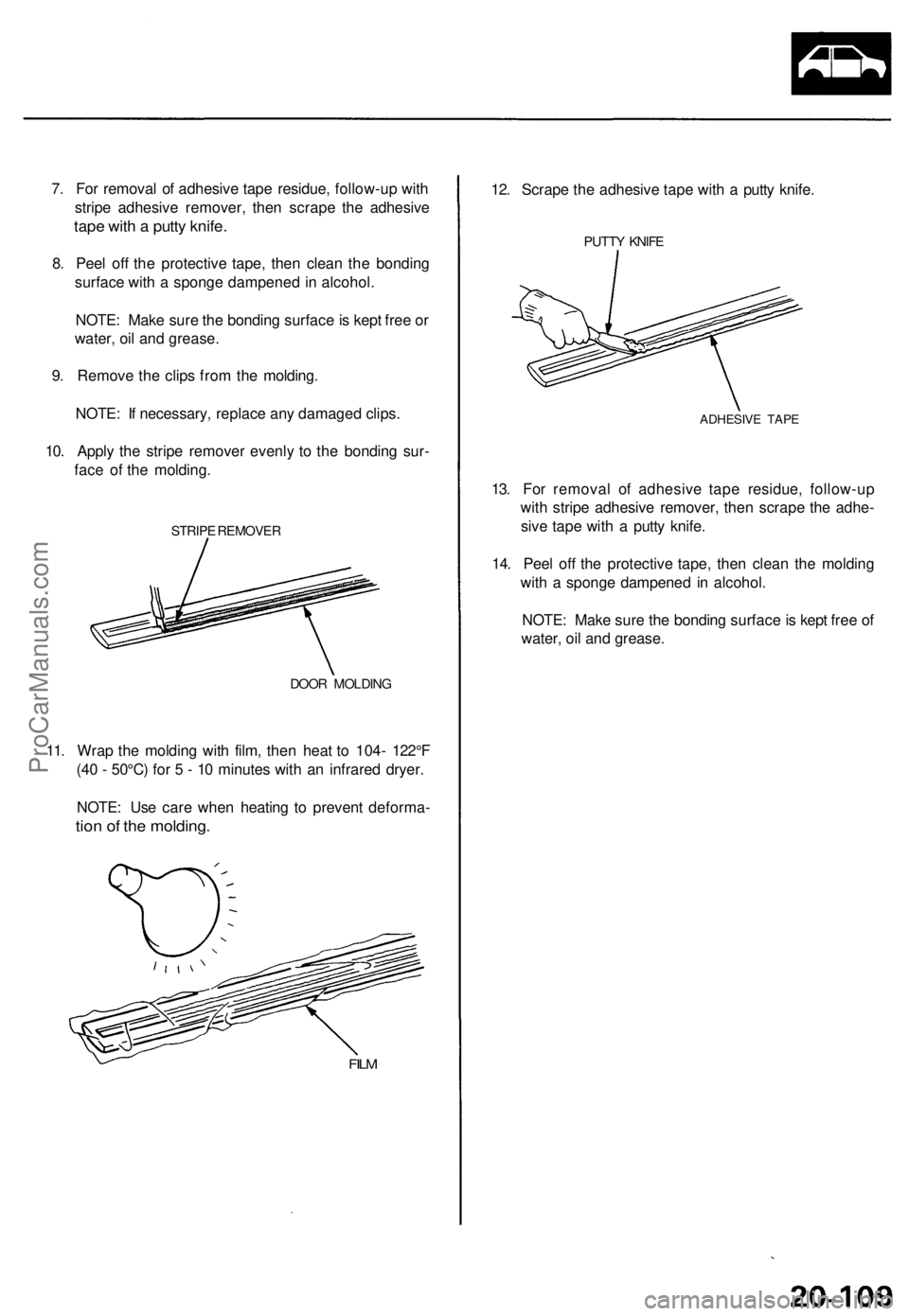
7. For removal of adhesive tape residue, follow-up with
stripe adhesive remover, then scrape the adhesive
tape with a putty knife.
8. Peel off the protective tape, then clean the bonding
surface with a sponge dampened in alcohol.
NOTE: Make sure the bonding surface is kept free or
water, oil and grease.
9. Remove the clips from the molding.
NOTE: If necessary, replace any damaged clips.
10. Apply the stripe remover evenly to the bonding sur-
face of the molding.
STRIPE REMOVER
DOOR MOLDING
11. Wrap the molding with film, then heat to 104- 122°F
(40 - 50°C) for 5 - 10 minutes with an infrared dryer.
NOTE: Use care when heating to prevent deforma-
tion of the molding.
FILM
12. Scrape the adhesive tape with a putty knife.
PUTTY KNIFE
ADHESIVE TAPE
13. For removal of adhesive tape residue, follow-up
with stripe adhesive remover, then scrape the adhe-
sive tape with a putty knife.
14. Peel off the protective tape, then clean the molding
with a sponge dampened in alcohol.
NOTE: Make sure the bonding surface is kept free of
water, oil and grease.ProCarManuals.com
Page 1463 of 1771
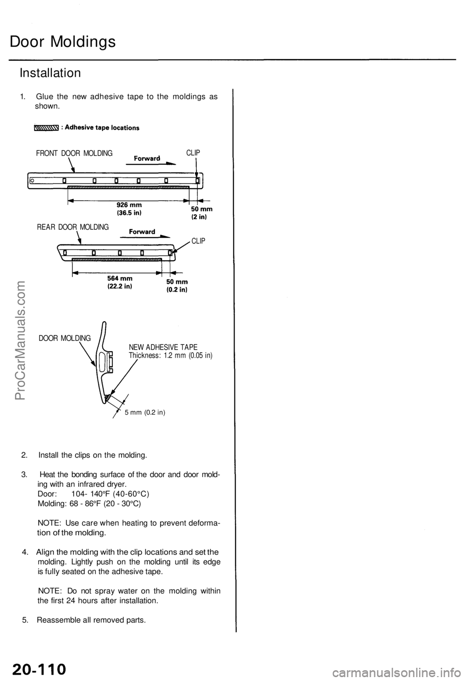
Door Moldings
Installation
1. Glue the new adhesive tape to the moldings as
shown.
FRONT DOOR MOLDING
CLIP
DOOR MOLDING
NEW ADHESIVE TAPE
Thickness: 1.2 mm (0.05 in)
5 mm
(0.2
in)
2. Install the clips on the molding.
3. Heat the bonding surface of the door and door mold-
ing with an infrared dryer.
Door: 104- 140°F (40-60°C)
Molding: 68 - 86°F (20 - 30°C)
NOTE: Use care when heating to prevent deforma-
tion of the molding.
4. Align the molding with the clip locations and set the
molding. Lightly push on the molding until its edge
is fully seated on the adhesive tape.
NOTE: Do not spray water on the molding within
the first 24 hours after installation.
5. Reassemble all removed parts.
REAR DOOR MOLDING
CLIPProCarManuals.com
Page 1464 of 1771
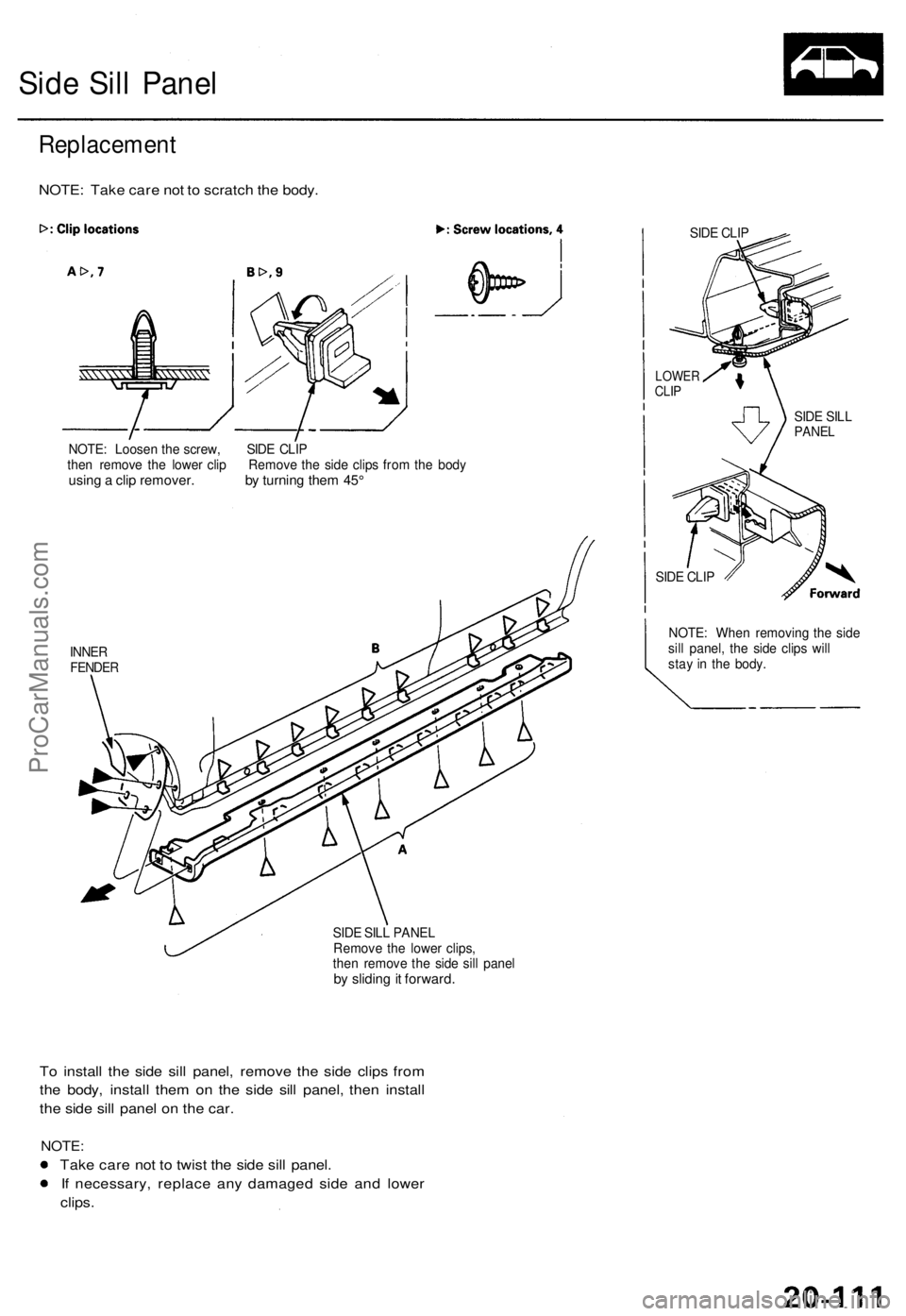
Side Sil l Pane l
NOTE : Loose n th e screw , SID E CLI P
the n remov e th e lowe r cli p Remov e th e sid e clip s fro m th e bod y
using a cli p remover . b y turnin g the m 45 °
INNE RFENDE R
SIDE SIL L PANE L
Remov e th e lowe r clips ,
the n remov e th e sid e sil l pane l
by slidin g it forward .
SIDE CLI P
LOWE RCLIP
SID E CLI P
NOTE : Whe n removin g th e sid e
sil l panel , th e sid e clip s wil l
sta y i n th e body .
To instal l th e sid e sil l panel , remov e th e sid e clip s fro m
th e body , instal l the m o n th e sid e sil l panel , the n instal l
th e sid e sil l pane l o n th e car .
NOTE :
Take car e no t t o twis t th e sid e sil l panel .
I f necessary , replac e an y damage d sid e an d lowe r
clips .
Replacemen t
NOTE: Tak e car e no t t o scratc h th e body .
SIDE SIL LPANE L
ProCarManuals.com
Page 1465 of 1771
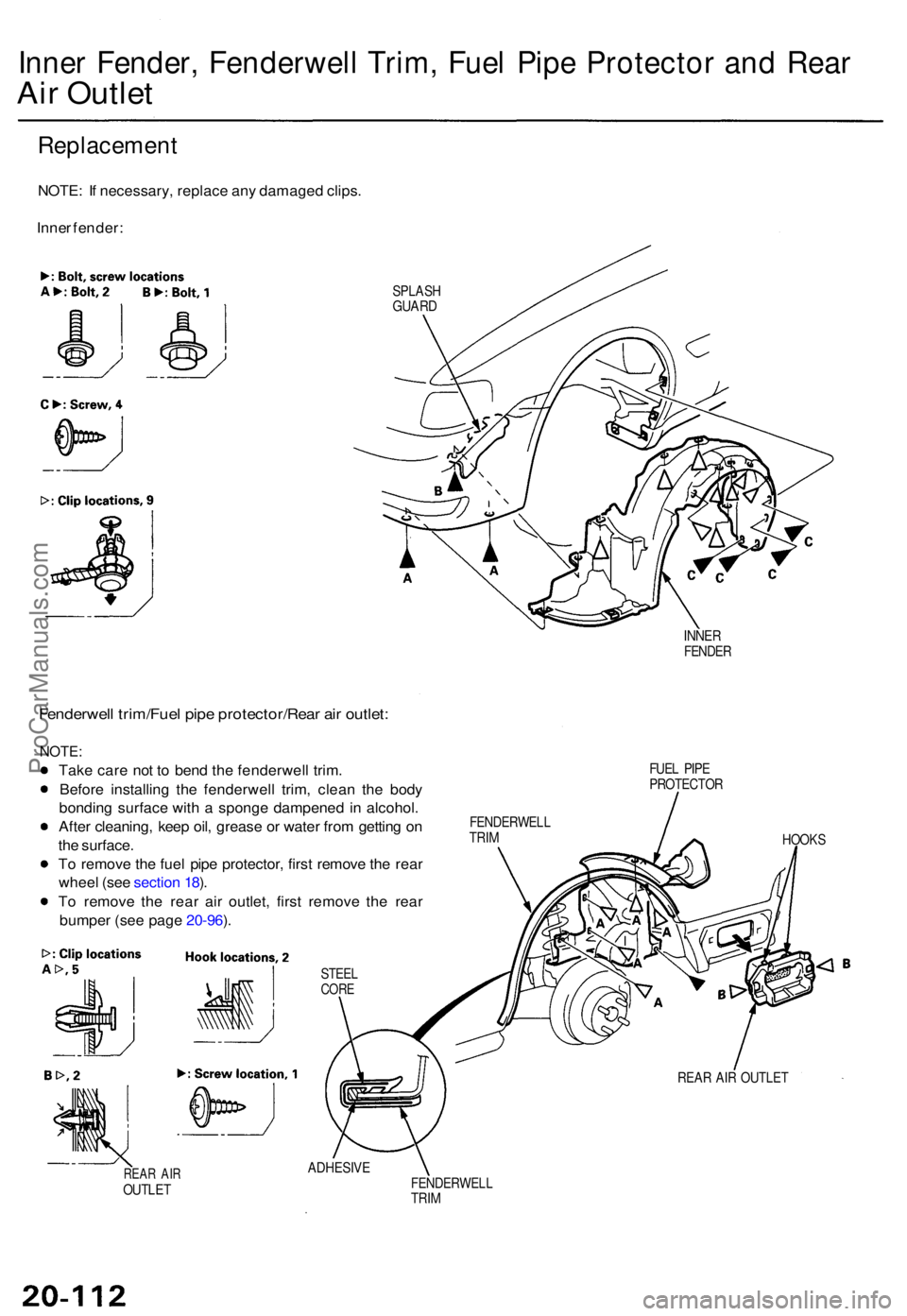
Inner Fender , Fenderwel l Trim , Fue l Pip e Protecto r an d Rea r
Air Outle t
NOTE : I f necessary , replac e an y damage d clips .
Inne r fender :
SPLAS HGUARD
INNER
FENDE R
Fenderwel l trim/Fue l pip e protector/Rea r ai r outlet :
NOTE :
Take car e no t t o ben d th e fenderwel l trim .
Befor e installin g th e fenderwel l trim , clea n th e bod y
bondin g surfac e wit h a spong e dampene d i n alcohol .
Afte r cleaning , kee p oil , greas e o r wate r fro m gettin g o n
th e surface .
T o remov e th e fue l pip e protector , firs t remov e th e rea r
whee l (se e sectio n 18 ).
T o remov e th e rea r ai r outlet , firs t remov e th e rea r
bumpe r (se e pag e 20-96 ).
STEE LCORE
REAR AI ROUTLE T ADHESIV
E
FENDERWEL LTRIM
FUE L PIP E
PROTECTO R
FENDERWEL L
TRIM
HOOK S
REA R AI R OUTLE T
Replacemen t
ProCarManuals.com
Page 1466 of 1771
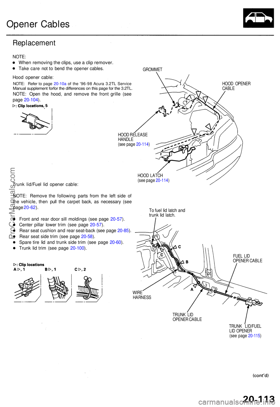
Opener Cable s
Replacemen t
NOTE:
When removin g th e clips , us e a cli p remover .
Take car e no t t o ben d th e opene r cables .
Hoo d opene r cable :
NOTE : Ope n th e hood , an d remov e th e fron t grill e (se e
pag e 20-104 ).GROMME T
HOO D RELEAS E
HANDL E
(se e pag e 20-114 ) HOO
D OPENE R
CABLE
Trunk lid/Fue l li d opene r cable :
HOOD LATC H
(se e pag e 20-114 )
NOTE: Remov e th e followin g part s fro m th e lef t sid e o f
th e vehicle , the n pul l th e carpe t back , a s necessar y (se e
pag e 20-62 ).
Fron t an d rea r doo r sil l molding s (se e pag e 20-57 ).
Cente r pilla r lowe r tri m (se e pag e 20-57 ).
Rea r sea t cushio n an d rea r seat-bac k (se e pag e 20-85 ).
Rea r sea t sid e tri m (se e pag e 20-58 ).
Spar e tir e li d an d trun k sid e tri m (se e pag e 20-60 ).
Trun k li d tri m (se e pag e 20-100 ).
T o fue l li d latc h an dtrun k li d latch .
FUEL LI D
OPENE R CABL E
WIR E
HARNES S
TRUNK LI D
OPENE R CABL E
TRUNK LID/FUE L
LI D OPENE R
(se e pag e 20-115 )
NOTE: Refe r t o page 20-10a of th e '96-9 8 Acura 3.2TL Service Manual supplement for for the differences on this page for the 3.2TL.
ProCarManuals.com
Page 1467 of 1771
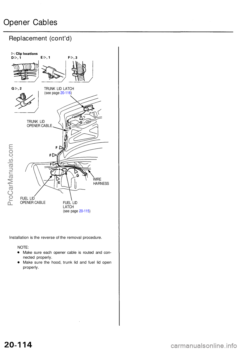
Opener Cable s
Replacemen t (cont'd )
TRUNK LI D LATC H
(se e pag e 20-116 )
WIRE
HARNES S
FUE L LI D
OPENE R CABL E
FUEL LI D
LATC H
(se e pag e 20-115 )
Installatio n is th e revers e o f th e remova l procedure .
NOTE:
Make sur e eac h opene r cabl e i s route d an d con -
necte d properly .
Mak e sur e th e hood , trun k li d an d fue l li d ope n
properly .
TRUNK LI D
OPENE R CABL E
ProCarManuals.com
Page 1468 of 1771
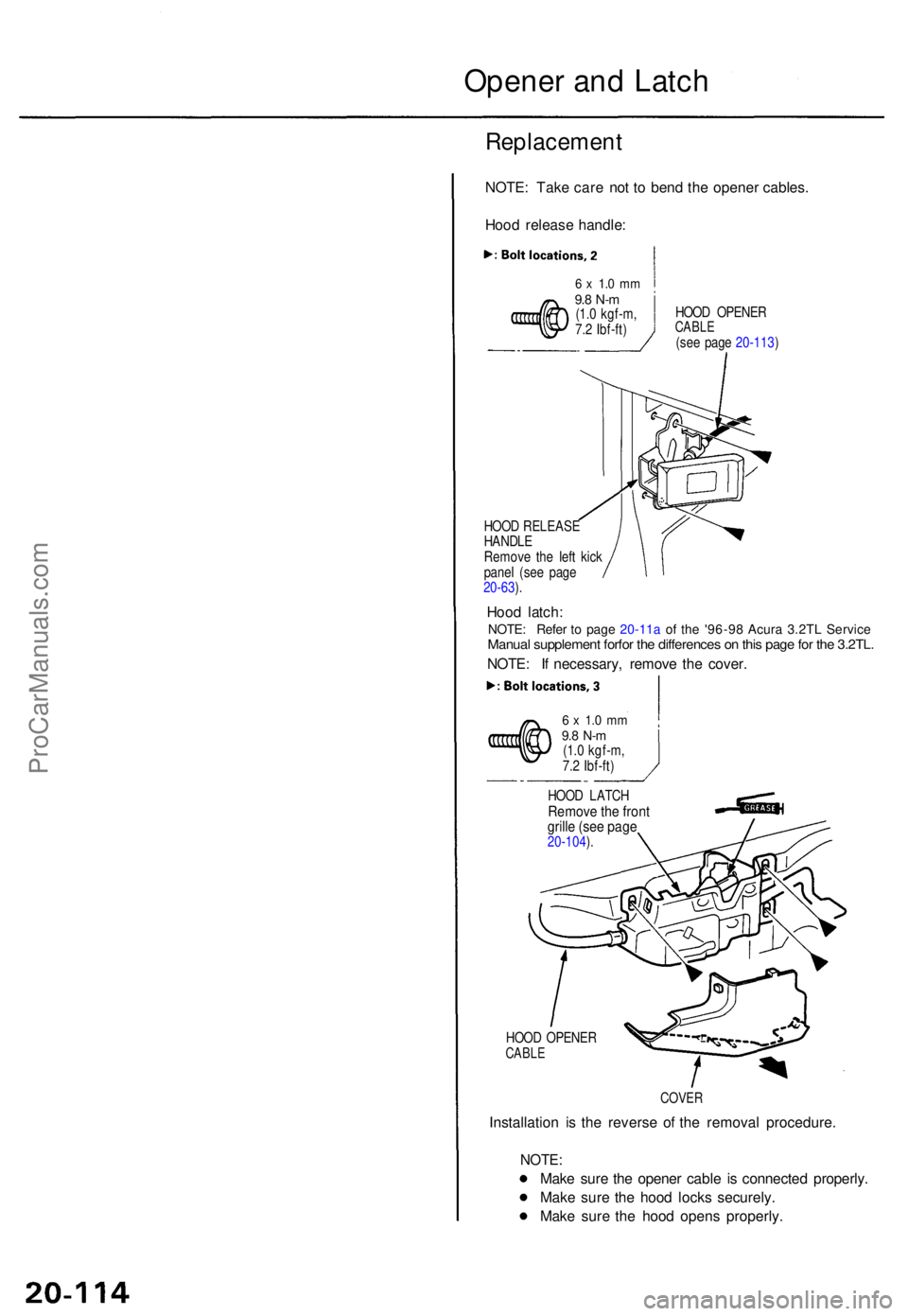
Opener an d Latc h
Replacemen t
NOTE: Tak e car e no t t o ben d th e opene r cables .
Hoo d releas e handle :
HOOD OPENE RCABLE(see pag e 20-113 )
HOO D RELEAS E
HANDL E
Remov e th e lef t kic k
pane l (se e pag e
20-63 ).
Hoo d latch :
NOTE : I f necessary , remov e th e cover .
6 x 1. 0 m m9.8 N- m(1.0 kgf-m ,
7. 2 Ibf-ft )
HOO D LATC H
Remov e th e fron t
grill e (se e pag e
20-104 ).
HOO D OPENE R
CABLE
COVE R
Installatio n i s th e revers e o f th e remova l procedure .
NOTE:
Make sur e th e opene r cabl e i s connecte d properly .
Mak e sur e th e hoo d lock s securely .
Mak e sur e th e hoo d open s properly .
6 x 1. 0 m m9.8 N- m(1.0 kgf-m ,
7. 2 Ibf-ft )
NOTE : Refe r t o page 20-11a of th e '96-9 8 Acura 3.2TL Service Manual supplement forfor the differences on this page for the 3.2TL.
ProCarManuals.com
Page 1469 of 1771
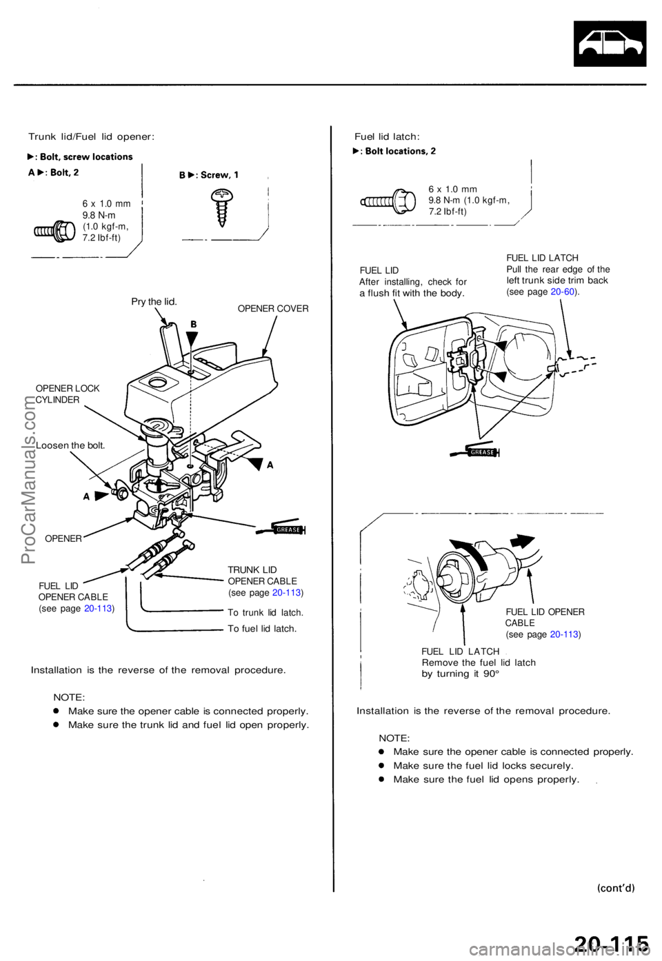
Trunk lid/Fue l li d opener :
6 x 1. 0 m m9.8 N- m(1.0 kgf-m ,
7. 2 Ibf-ft )
Pry th e lid .OPENE R COVE R
OPENE R LOC K
CYLINDE R
Loosen th e bolt .
OPENE R
FUE L LI D
OPENE R CABL E
(se e pag e 20-113 )
TRUNK LI DOPENE R CABL E
(se e pag e 20-113 )
T o trun k li d latch .
To fue l li d latch .
Installatio n i s th e revers e o f th e remova l procedure .
NOTE :
Mak e sur e th e opene r cabl e is connecte d properly .
Mak e sur e th e trun k li d an d fue l li d ope n properly . Fue
l li d latch :
6 x 1. 0 m m9.8 N- m (1. 0 kgf-m ,
7. 2 Ibf-ft )
FUE L LI D
Afte r installing , chec k fo r
a flus h fi t wit h th e body .
FUEL LI D LATC H
Pul l th e rea r edg e o f th e
left trun k sid e tri m bac k(see pag e 20-60 ).
FUE L LI D OPENE R
CABLE(see pag e 20-113 )
FUE L LI D LATC H
Remove th e fue l li d latc hby turnin g i t 90 °
Installatio n i s th e revers e o f th e remova l procedure .
NOTE:
Make sur e th e opene r cabl e is connecte d properly .
Mak e sur e th e fue l li d lock s securely .
Mak e sur e th e fue l li d open s properly .
ProCarManuals.com
Page 1470 of 1771
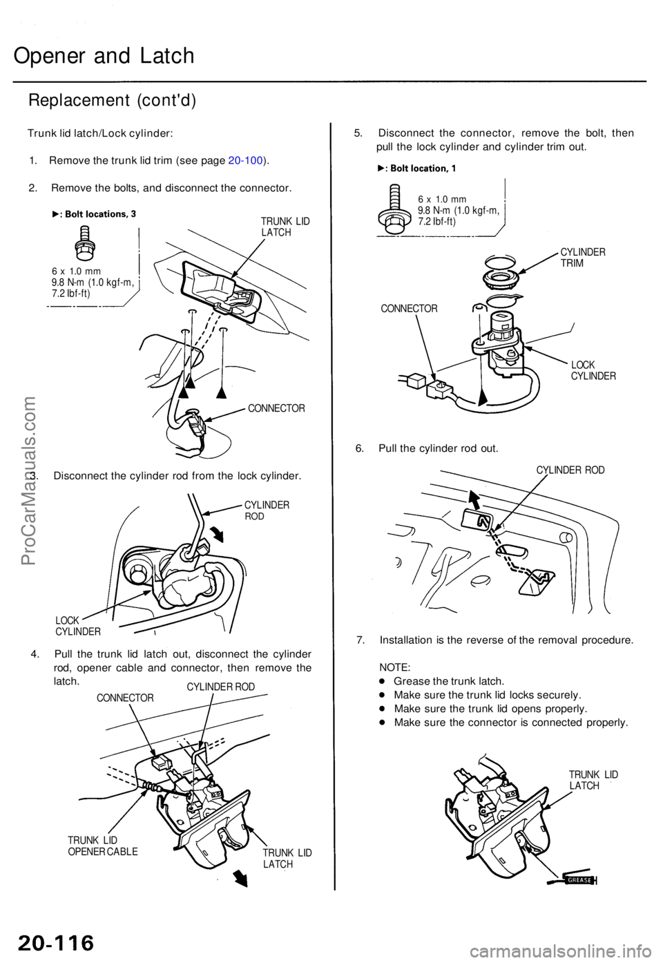
Opener an d Latc h
Replacemen t (cont'd )
Trunk li d latch/Loc k cylinder :
1 . Remov e th e trun k li d tri m (se e pag e 20-100 ).
2 . Remov e th e bolts , an d disconnec t th e connector .
TRUNK LI DLATC H
6 x 1. 0 m m9.8 N- m (1. 0 kgf-m ,
7. 2 Ibf-ft )
CONNECTOR
3. Disconnec t th e cylinde r ro d fro m th e loc k cylinder .
CYLINDE RROD
LOC KCYLINDE R
4. Pul l th e trun k li d latc h out , disconnec t th e cylinde r
rod , opene r cabl e an d connector , the n remov e th e
latch .
CONNECTO RCYLINDE
R RO D
TRUN K LI D
OPENE R CABL E
TRUNK LI D
LATC H
5. Disconnec t th e connector , remov e th e bolt , the n
pul l th e loc k cylinde r an d cylinde r tri m out .
6 x 1. 0 m m9.8 N- m (1. 0 kgf-m ,
7. 2 Ibf-ft )
CONNECTO R
CYLINDERTRIM
LOC KCYLINDE R
6. Pul l th e cylinde r ro d out .
CYLINDE R RO D
7. Installatio n i s th e revers e o f th e remova l procedure .
NOTE:
Greas e th e trun k latch .
Mak e sur e th e trun k li d lock s securely .
Mak e sur e th e trun k li d open s properly .
Mak e sur e th e connecto r i s connecte d properly .
TRUNK LI D
LATC H
ProCarManuals.com