ACURA TL 1995 Service Repair Manual
Manufacturer: ACURA, Model Year: 1995, Model line: TL, Model: ACURA TL 1995Pages: 1771, PDF Size: 62.49 MB
Page 1491 of 1771
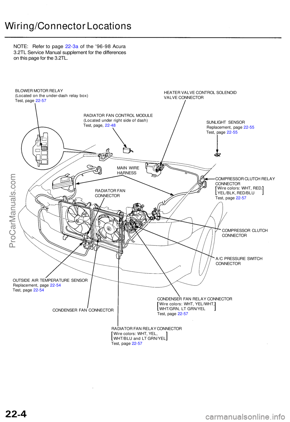
Wiring/Connector Location s
BLOWER MOTO R RELA Y
(Locate d o n th e under-das h rela y box )
Test , pag e 22-5 7 HEATE
R VALV E CONTRO L SOLENOI D
VALV E CONNECTO R
SUNLIGH T SENSO R
Replacement , pag e 22-5 5
Test , pag e 22-5 5
COMPRESSO R CLUTC H RELA Y
CONNECTO R
Wir e colors : WHT , RED ,
YEL/BLK , RED/BL U
Test , pag e 22-5 7
COMPRESSO R CLUTC H
CONNECTO R
A/ C PRESSUR E SWITC H
CONNECTO R
OUTSID E AI R TEMPERATUR E SENSO R
Replacement , pag e 22-5 4
Test , pag e 22-5 4
CONDENSE R FA N CONNECTO R CONDENSE
R FA N RELA Y CONNECTO R
Wir e colors : WHT , YEL/WHT ,
WHT/GRN, L T GRN/YE L
Test , pag e 22-5 7
RADIATO R FA N RELA Y CONNECTO R
Wir e colors : WHT , YEL ,
WHT/BL U an d L T GRN/YE L
Test , pag e 22-5 7
RADIATO
R FA N
CONNECTO RMAI
N WIR E
HARNES S
RADIATO R FA N CONTRO L MODUL E
(Locate d unde r righ t sid e o f dash )
Test , page , 22-4 8
NOTE : Refe r t o page 22-3a of the '96-9 8 Acura
3.2TL Servic e Manual supplement for the differences
on this page for the 3.2TL.
ProCarManuals.com
Page 1492 of 1771
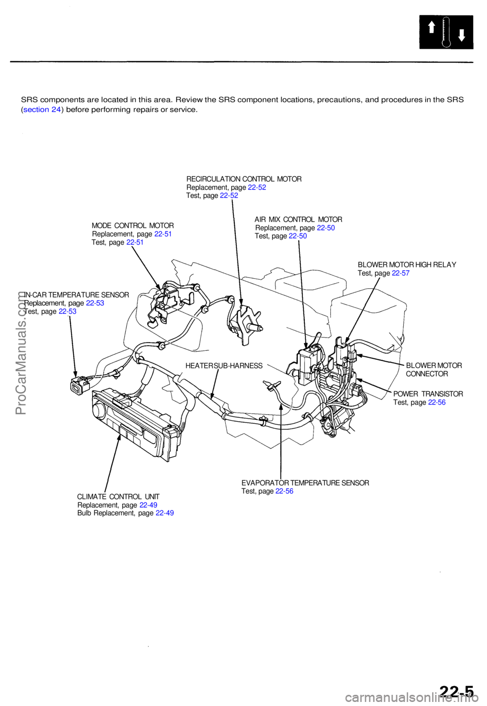
SRS component s ar e locate d in thi s area . Revie w th e SR S componen t locations , precautions , an d procedure s in th e SR S
( sectio n 24 ) befor e performin g repair s o r service .
RECIRCULATIO N CONTRO L MOTO R
Replacement , pag e 22-5 2
Test , pag e 22-5 2
MOD E CONTRO L MOTO R
Replacement , pag e 22-5 1
Test , pag e 22-5 1 AI
R MI X CONTRO L MOTO R
Replacement , pag e 22-5 0
Test , pag e 22-5 0
IN-CA R TEMPERATUR E SENSO R
Replacement , pag e 22-5 3Test, pag e 22-5 3 BLOWE
R MOTO R HIG H RELA Y
Test , pag e 22-5 7
BLOWE R MOTO R
CONNECTO R
POWE R TRANSISTO R
Test , pag e 22-5 6
CLIMAT E CONTRO L UNI T
Replacement , pag e 22-4 9
Bul b Replacement , pag e 22-4 9 EVAPORATO
R TEMPERATUR E SENSO R
Test , pag e 22-5 6
HEATE
R SUB-HARNES S
ProCarManuals.com
Page 1493 of 1771
Description
Outline
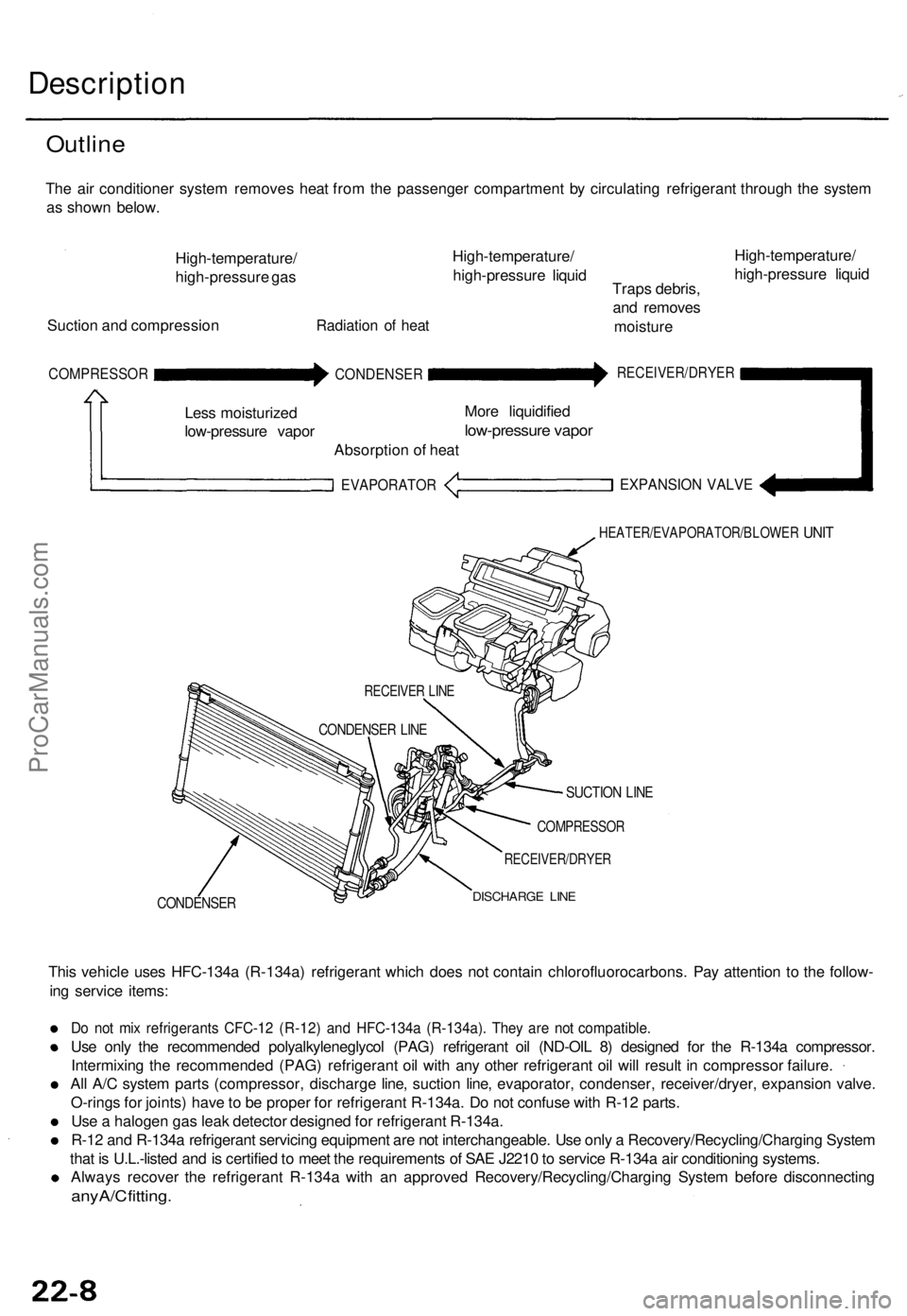
The air conditioner system removes heat from the passenger compartment by circulating refrigerant through the system
as shown below.
High-temperature/
high-pressure gas
Suction and compression
Radiation of heat
High-temperature/
high-pressure liquid
Traps debris,
and removes
moisture
High-temperature/
high-pressure liquid
COMPRESSOR
Less moisturized
low-pressure vapor
CONDENSER
Absorption of heat
EVAPORATOR
More liquidified
low-pressure vapor
RECEIVER/DRYER
EXPANSION VALVE
HEATER/EVAPORATOR/BLOWER
UNIT
CONDENSER
SUCTION LINE
COMPRESSOR
RECEIVER/DRYER
DISCHARGE LINE
This vehicle uses HFC-134a (R-134a) refrigerant which does not contain chlorofluorocarbons. Pay attention to the follow-
ing service items:
Do not mix refrigerants CFC-12 (R-12) and HFC-134a (R-134a). They are not compatible.
Use only the recommended polyalkyleneglycol (PAG) refrigerant oil (ND-OIL 8) designed for the R-134a compressor.
Intermixing the recommended (PAG) refrigerant oil with any other refrigerant oil will result in compressor failure.
All A/C system parts (compressor, discharge line, suction line, evaporator, condenser, receiver/dryer, expansion valve.
O-rings for joints) have to be proper for refrigerant R-134a. Do not confuse with R-12 parts.
Use a halogen gas leak detector designed for refrigerant R-134a.
R-12 and R-134a refrigerant servicing equipment are not interchangeable. Use only a Recovery/Recycling/Charging System
that is U.L.-listed and is certified to meet the requirements of SAE J2210 to service R-134a air conditioning systems.
Always recover the refrigerant R-134a with an approved Recovery/Recycling/Charging System before disconnecting
any A/C fitting.
RECEIVER LINE
CONDENSER LINEProCarManuals.com
Page 1494 of 1771
Troubleshooting
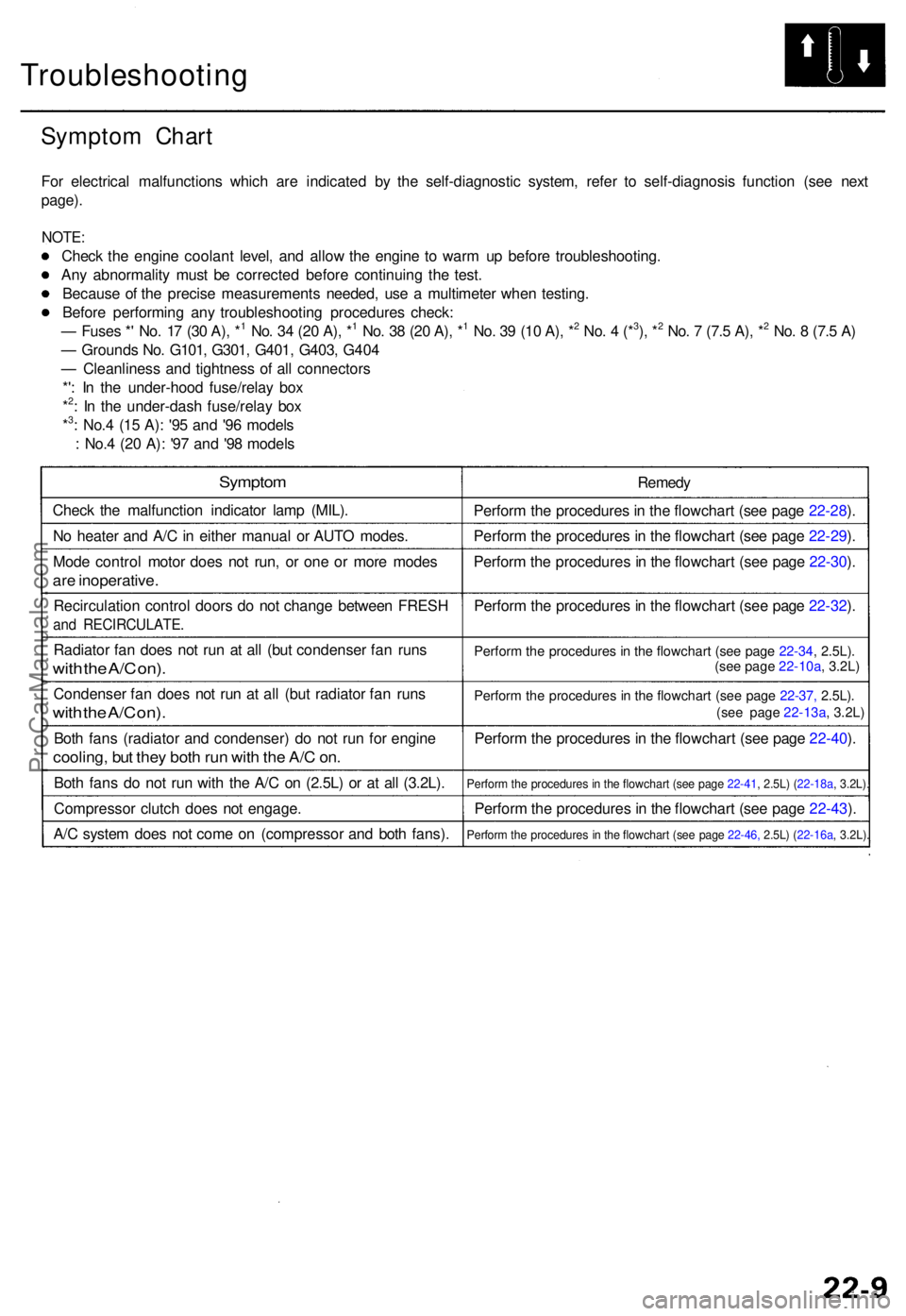
Symptom Char t
For electrica l malfunction s whic h ar e indicate d b y th e self-diagnosti c system , refe r t o self-diagnosi s functio n (se e nex t
page) .
NOTE :
Check th e engin e coolan t level , an d allo w th e engin e t o war m u p befor e troubleshooting .
An y abnormalit y mus t b e correcte d befor e continuin g th e test .
Becaus e o f th e precis e measurement s needed , us e a multimete r whe n testing .
Befor e performin g an y troubleshootin g procedure s check :
— Fuse s * ' No . 1 7 (3 0 A) , *
1 No . 3 4 (2 0 A) , *1 No . 3 8 (2 0 A) , *1 No . 3 9 (1 0 A) , *2 No . 4 (*3), *2 No . 7 (7. 5 A) , *2 No . 8 (7. 5 A )
— Ground s No . G101 , G301 , G401 , G403 , G40 4
— Cleanlines s an d tightnes s o f al l connector s
*' : I n th e under-hoo d fuse/rela y bo x
*
2: I n th e under-das h fuse/rela y bo x
*3: No. 4 (1 5 A) : '9 5 an d '9 6 model s
: No. 4 (2 0 A) : '9 7 an d '9 8 model s
Sympto m
Check th e malfunctio n indicato r lam p (MIL) .
N o heate r an d A/ C in eithe r manual or AUT O modes .
Mod e contro l moto r doe s no t run , o r on e o r mor e mode s
are inoperative .
Recirculatio n contro l door s d o no t chang e betwee n FRES H
and RECIRCULATE .
Radiator fa n doe s no t ru n a t al l (bu t condense r fa n run s
with th e A/ C on) .
Condense r fa n doe s no t ru n a t al l (bu t radiato r fa n run s
with th e A/ C on) .
Both fan s (radiato r an d condenser ) d o no t ru n fo r engin e
cooling , bu t the y bot h ru n wit h th e A/ C on .
Bot h fan s d o no t ru n wit h th e A/ C on (2.5L) or at all (3.2L) .
Compresso r clutc h doe s no t engage .
A/ C syste m doe s no t com e o n (compresso r an d bot h fans) . Remed
y
Perfor m th e procedure s in th e flowchar t (se e pag e 22-28 ).
Perfor m th e procedure s in th e flowchar t (se e pag e 22-29 ).
Perfor m th e procedure s in th e flowchar t (se e pag e 22-30 ).
Perfor m th e procedure s in th e flowchar t (se e pag e 22-32 ).
Perfor m th e procedure s in th e flowchar t (se e pag e 22-34 , 2.5L) .
Perfor m th e procedure s i n th e flowchar t (se e pag e 22-37, 2.5L).
Perfor m th e procedure s in th e flowchar t (se e pag e 22-40 ).
Perfor m th e procedure s in th e flowchar t (se e pag e 22-41 , 2.5L) ( 22-18a, 3.2L).
Perfor m th e procedure s in th e flowchar t (se e pag e 22-43 ).
Perfor m th e procedure s i n th e flowchar t (se e pag e 22-46, 2.5L) (22-16a , 3.2L).
(see page 22-10a, 3.2L)
(see page 22-13a , 3.2L)
ProCarManuals.com
Page 1495 of 1771
Troubleshooting
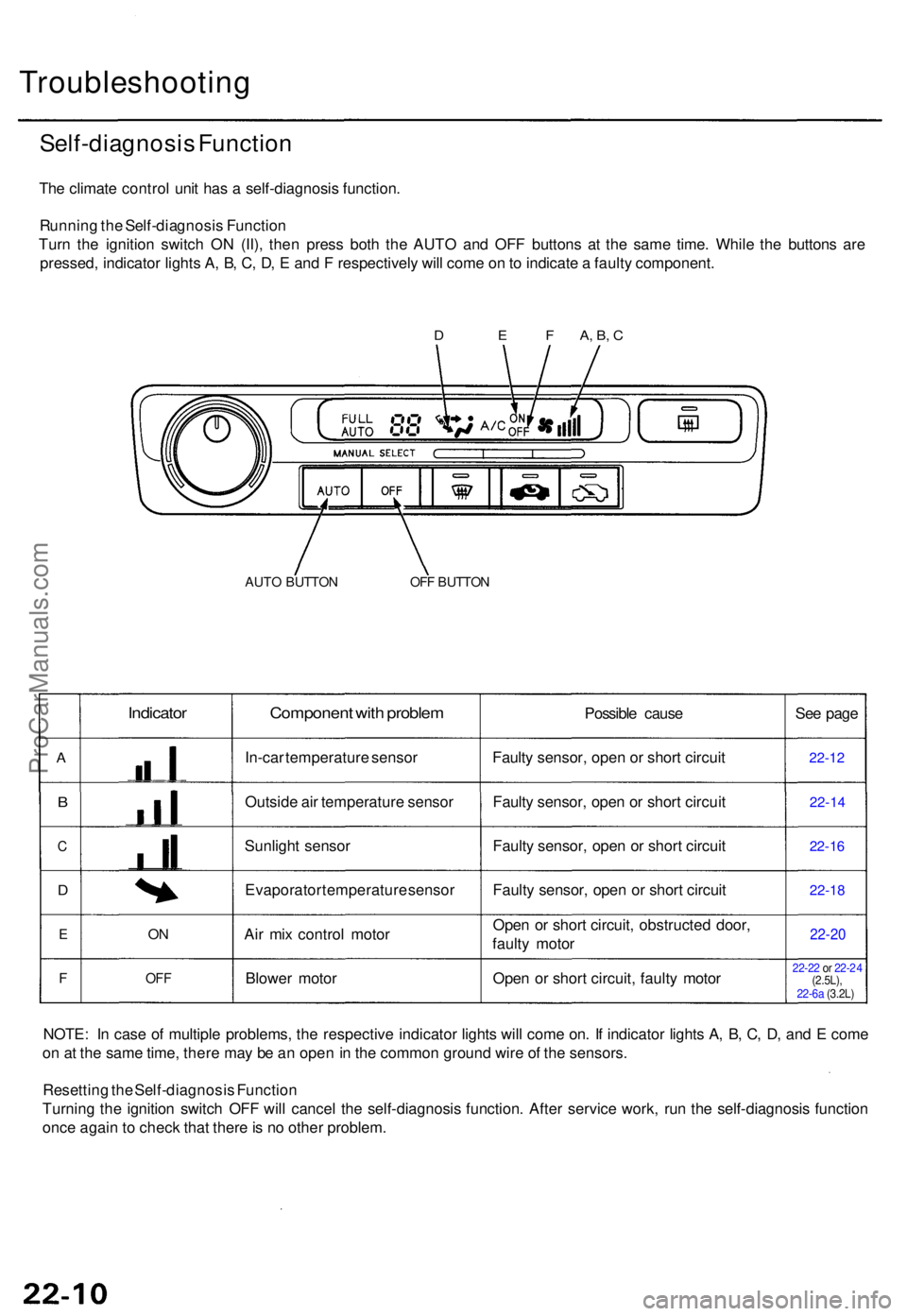
Self-diagnosis Functio n
The climat e contro l uni t ha s a self-diagnosi s function .
Runnin g th e Self-diagnosi s Functio n
Tur n th e ignitio n switc h O N (II) , the n pres s bot h th e AUT O an d OF F button s a t th e sam e time . Whil e th e button s ar e
pressed , indicato r light s A , B , C , D , E an d F respectivel y wil l com e o n to indicat e a fault y component .
AUTO BUTTO NOFF BUTTO N
A
B
C
D
E
F
Indicator
ON
OF F
Componen t wit h proble m
In-car temperatur e senso r
Outsid e ai r temperatur e senso r
Sunligh t senso r
Evaporato r temperatur e senso r
Ai r mi x contro l moto r
Blowe r moto r Possibl
e caus e
Fault y sensor , ope n o r shor t circui t
Fault y sensor , ope n o r shor t circui t
Fault y sensor , ope n o r shor t circui t
Fault y sensor , ope n o r shor t circui t
Ope n o r shor t circuit , obstructe d door ,
fault y moto r
Ope n o r shor t circuit , fault y moto r Se
e pag e22-1 2
22-1 4
22-16
22-1 8
22-2 0
22-22 or 22- 24
(2.5L),
NOTE : I n cas e o f multipl e problems , th e respectiv e indicato r light s wil l com e on . I f indicato r light s A , B , C , D , an d E com e
o n a t th e sam e time , ther e ma y b e a n ope n in th e commo n groun d wir e o f th e sensors .
Resettin g th e Self-diagnosi s Functio n
Turnin g th e ignitio n switc h OF F wil l cance l th e self-diagnosi s function . Afte r servic e work , ru n th e self-diagnosi s functio n
onc e agai n to chec k tha t ther e is n o othe r problem.
D E F A, B , C
22-6a (3.2L)
ProCarManuals.com
Page 1496 of 1771
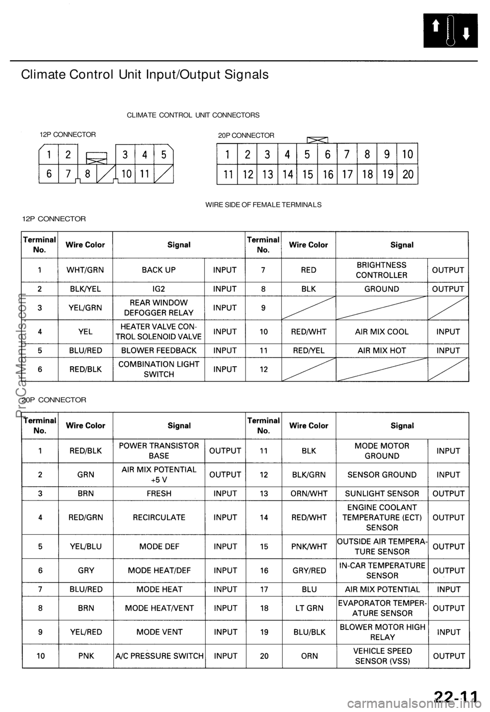
Climate Contro l Uni t Input/Outpu t Signal s
12P CONNECTO RCLIMAT
E CONTRO L UNI T CONNECTOR S
20 P CONNECTO R
WIR E SID E O F FEMAL E TERMINAL S
12P CONNECTO R
20 P CONNECTO R
ProCarManuals.com
Page 1497 of 1771
Troubleshooting
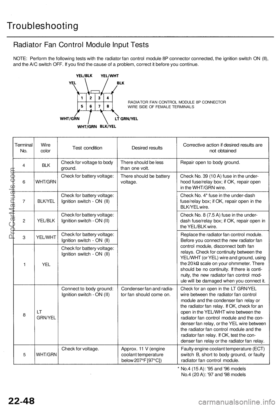
Radiator Fan Control Module Input Tests
NOTE: Perform the following tests with the radiator fan control module 8P connector connected, the ignition switch ON (II),
and the A/C switch OFF. If you find the cause of a problem, correct it before you continue.
RADIATOR FAN CONTROL MODULE 8P CONNECTOR
WIRE SIDE OF FEMALE TERMINALS
Terminal
No.
4
6
7
2
3
1
8
5
Wire
color
BLK
WHT/GRN
BLK/YEL
YEL/BLK
YEL/WHT
YEL
LT
GRN/YEL
WHT/GRN
Test condition
Check for voltage to body
ground.
Check for battery voltage:
Check for battery voltage:
Ignition switch - ON (II)
Check for battery voltage:
Ignition switch - ON (II)
Check for battery voltage:
Ignition switch - ON (II)
Check for battery voltage:
Ignition switch - ON (II)
Connect to body ground:
Ignition switch - ON (II)
Check for voltage.
Desired results
There should be less
than one volt.
There should be battery
voltage.
Condenser fan and radia-
tor fan should come on.
Approx. 11 V (engine
coolant temperature
below 207°F [97°C])
Corrective action if desired results are
not obtained
Repair open to body ground.
Check No. 39 (10 A) fuse in the under-
hood fuse/relay box; if OK, repair open
in the WHT/GRN wire.
Check No. 4* fuse in the under-dash
fuse/relay box; if OK, repair open in the
BLK/YEL wire.
Check No. 8 (7.5 A) fuse in the under-
dash fuse/relay box; if OK, repair open in
the YEL/BLK wire.
Replace the radiator fan control module.
Before you connect the new radiator fan
control module, disconnect both fan
relays. Check for continuity between the
YEL/WHT (or YEL) wire and ground, using
the 20 k scale on your ohmmeter. There
should be no continuity. If there is conti-
nuity, the new radiator fan control mod-
ule will be damaged when you connect it.
Check for an open in the LT GRN/YEL
wire between the radiator fan control
module and the condenser fan relay or
the radiator fan relay. If OK, check for an
open in the YEL/WHT wire between the
radiator fan control module and the con-
denser fan relay, or the YEL wire between
the radiator fan control module and the
radiator fan relay. If OK, test the con-
denser fan relay or the radiator fan relay.
Faulty engine coolant temperature (ECT)
switch B, short to body ground, or faulty
radiator fan control module.
* No.4 (15 A): '95 and '96 models
No.4 (20 A): '97 and '98 modelsProCarManuals.com
Page 1498 of 1771
Climate Contro l Uni t
Replacemen t
Bulb Replacemen t
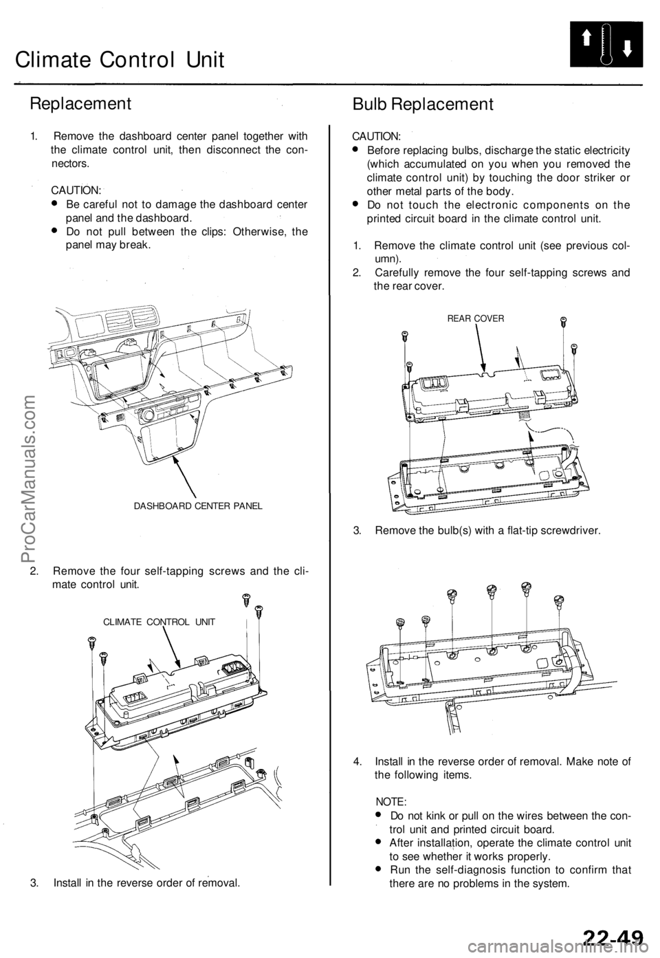
1. Remov e th e dashboar d cente r pane l togethe r wit h
th e climat e contro l unit , the n disconnec t th e con -
nectors .
CAUTION :
B e carefu l no t t o damag e th e dashboar d cente r
pane l an d th e dashboard .
D o no t pul l betwee n th e clips : Otherwise , th e
pane l ma y break .
DASHBOAR D CENTE R PANE L
2. Remov e th e fou r self-tappin g screw s an d th e cli -
mat e contro l unit .
CLIMAT E CONTRO L UNI T
3. Instal l i n th e revers e orde r o f removal . CAUTION
:
Befor e replacin g bulbs , discharg e th e stati c electricit y
(whic h accumulate d o n yo u whe n yo u remove d th e
climat e contro l unit ) b y touchin g th e doo r strike r o r
othe r meta l part s o f th e body .
D o no t touc h th e electroni c component s o n th e
printe d circui t boar d in th e climat e contro l unit .
1 . Remov e th e climat e contro l uni t (se e previou s col -
umn) .
2. Carefull y remov e th e fou r self-tappin g screw s an d
th e rea r cover .
REAR COVE R
3. Remov e th e bulb(s ) wit h a flat-ti p screwdriver .
4 . Instal l i n th e revers e orde r o f removal . Mak e not e o f
th e followin g items .
NOTE:
Do no t kin k o r pul l o n th e wire s betwee n th e con -
tro l uni t an d printe d circui t board .
Afte r installation , operat e th e climat e contro l uni t
t o se e whethe r i t work s properly .
Ru n th e self-diagnosi s functio n t o confir m tha t
ther e ar e n o problem s i n th e system .
ProCarManuals.com
Page 1499 of 1771
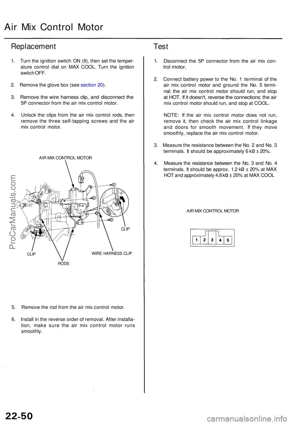
Air Mi x Contro l Moto r
Replacemen t
1. Tur n th e ignitio n switc h O N (II) , the n se t th e temper -
atur e contro l dia l o n MA X COOL . Tur n th e ignitio n
switc h OFF .
2 . Remov e th e glov e bo x (se e sectio n 20 ).
3 . Remov e th e wir e harnes s clip , an d disconnec t th e
5P connecto r fro m th e ai r mi x contro l motor .
4 . Unloc k th e clip s fro m th e ai r mi x contro l rods , the n
remov e th e thre e self-tappin g screw s an d th e ai r
mi x contro l motor .
AIR MI X CONTRO L MOTO R
CLIP
CLIP
WIR E HARNES S CLI P
ROD S
5. Remov e th e ro d fro m th e ai r mi x contro l motor .
6 . Instal l i n th e revers e orde r o f removal . Afte r installa -
tion , mak e sur e th e ai r mi x contro l moto r run s
smoothly .
Test
1. Disconnec t th e 5 P connecto r fro m th e ai r mi x con -
trol motor .
2. Connec t batter y powe r t o th e No . 1 termina l o f th e
ai r mi x contro l moto r an d groun d th e No . 5 termi -
nal ; th e ai r mi x contro l moto r shoul d run , an d sto p
at HOT . I f i t doesn't , revers e th e connections ; th e ai r
mi x contro l moto r shoul d run , an d sto p a t COOL .
NOTE : I f th e ai r mi x contro l moto r doe s no t run ,
remov e it , the n chec k th e ai r mi x contro l linkag e
an d door s fo r smoot h movement . I f the y mov e
smoothly , replac e th e ai r mi x contro l motor .
3 . Measur e th e resistanc e betwee n th e No . 2 an d No . 3
terminals . I t shoul d b e approximatel y 6 k ± 20% .
4 . Measur e th e resistanc e betwee n th e No . 3 an d No . 4
terminals . I t shoul d b e approx . 1. 2 k ± 20% at MA X
HOT an d approximatel y 4. 8 k ± 20% at MA X COO L
AIR MI X CONTRO L MOTO R
ProCarManuals.com
Page 1500 of 1771
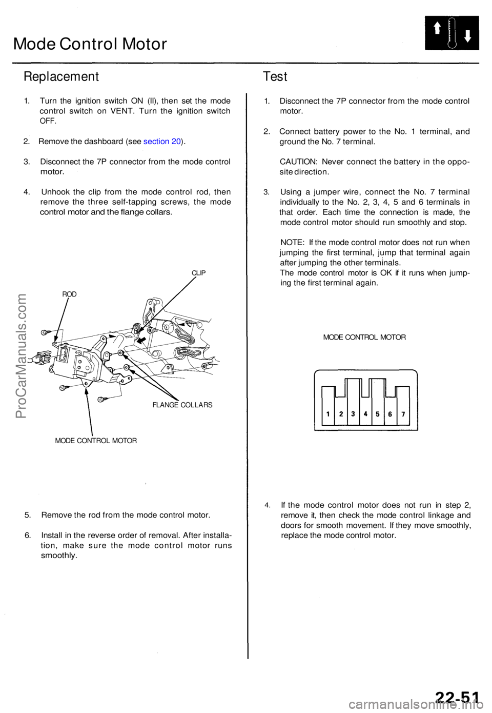
Mode Contro l Moto r
Replacemen t
1. Tur n th e ignitio n switc h O N (II) , the n se t th e mod e
contro l switc h o n VENT . Tur n th e ignitio n switc h
OFF.
2. Remov e th e dashboar d (se e sectio n 20 ).
3 . Disconnec t th e 7 P connecto r fro m th e mod e contro l
motor.
4. Unhoo k th e cli p fro m th e mod e contro l rod , the n
remov e th e thre e self-tappin g screws , th e mod e
contro l moto r an d th e flang e collars .
CLIP
RO D
FLANG E COLLAR S
MODE CONTRO L MOTO R
5. Remov e th e ro d fro m th e mod e contro l motor .
6 . Instal l i n th e revers e orde r o f removal . Afte r installa -
tion , mak e sur e th e mod e contro l moto r run s
smoothly .
Test
1. Disconnec t th e 7 P connecto r fro m th e mod e contro l
motor .
2 . Connec t batter y powe r t o th e No . 1 terminal , an d
groun d th e No . 7 terminal .
CAUTION : Neve r connec t th e batter y in th e oppo -
sit e direction .
3.
4 .
Usin g a jumpe r wire , connec t th e No . 7 termina l
individuall y t o th e No . 2 , 3 , 4 , 5 an d 6 terminal s i n
tha t order . Eac h tim e th e connectio n i s made , th e
mod e contro l moto r shoul d ru n smoothl y an d stop .
NOTE : I f th e mod e contro l moto r doe s no t ru n whe n
jumpin g th e firs t terminal , jum p tha t termina l agai n
afte r jumpin g th e othe r terminals .
Th e mod e contro l moto r i s O K if i t run s whe n jump -
in g th e firs t termina l again .
MODE CONTRO L MOTO R
If th e mod e contro l moto r doe s no t ru n i n ste p 2 ,
remov e it , the n chec k th e mod e contro l linkag e an d
door s fo r smoot h movement . I f the y mov e smoothly ,
replac e th e mod e contro l motor .
ProCarManuals.com