ACURA TL 1995 Service Repair Manual
Manufacturer: ACURA, Model Year: 1995, Model line: TL, Model: ACURA TL 1995Pages: 1771, PDF Size: 62.49 MB
Page 1501 of 1771
Recirculation Contro l Moto r
Replacemen t
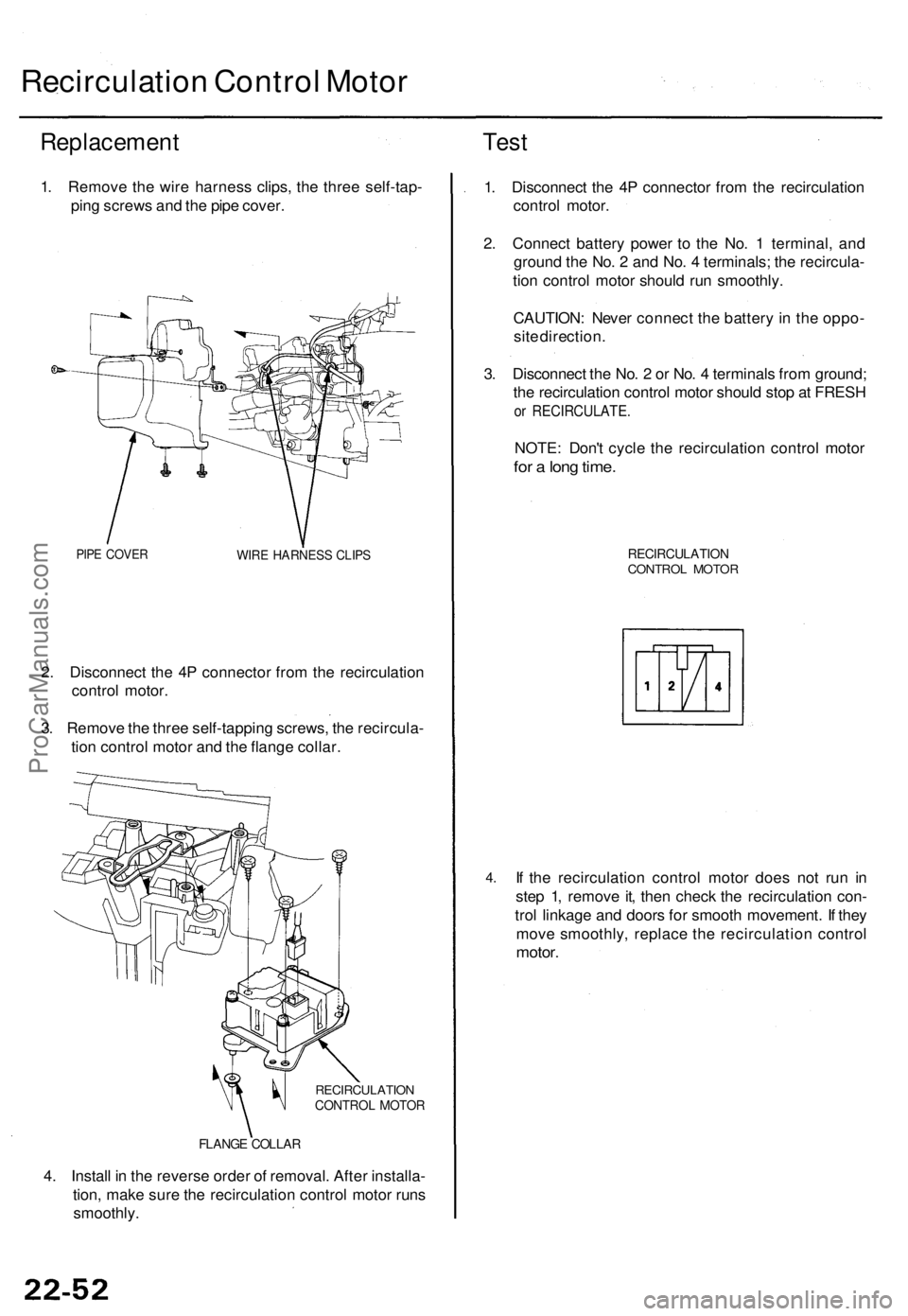
1. Remov e th e wir e harnes s clips , th e thre e self-tap -
pin g screw s an d th e pip e cover .
PIPE COVE RWIRE HARNES S CLIP S
2. Disconnec t th e 4 P connecto r fro m th e recirculatio n
contro l motor .
3 . Remov e th e thre e self-tappin g screws , th e recircula -
tio n contro l moto r an d th e flang e collar .
RECIRCULATIO NCONTROL MOTO R
FLANGE COLLA R
4. Instal l i n th e revers e orde r o f removal . Afte r installa -
tion , mak e sur e th e recirculatio n contro l moto r run s
smoothly .
Test
1. Disconnec t th e 4 P connecto r fro m th e recirculatio n
contro l motor .
2 . Connec t batter y powe r t o th e No . 1 terminal , an d
ground the No . 2 an d No . 4 terminals ; th e recircula -
tio n contro l moto r shoul d ru n smoothly .
CAUTION : Neve r connec t th e batter y in th e oppo -
sit e direction .
3 . Disconnec t th e No . 2 or No . 4 terminal s fro m ground ;
th e recirculatio n contro l moto r shoul d sto p a t FRES H
or RECIRCULATE .
NOTE: Don' t cycl e th e recirculatio n contro l moto r
for a lon g time .
RECIRCULATIO NCONTROL MOTO R
4.If th e recirculatio n contro l moto r doe s no t ru n i n
ste p 1 , remov e it , the n chec k th e recirculatio n con -
tro l linkag e an d door s fo r smoot h movement . I f the y
mov e smoothly , replac e th e recirculatio n contro l
motor.
ProCarManuals.com
Page 1502 of 1771
In-car Temperatur e Senso r
Replacemen t
1. Remove the dashboard center panel (see page
22-49).
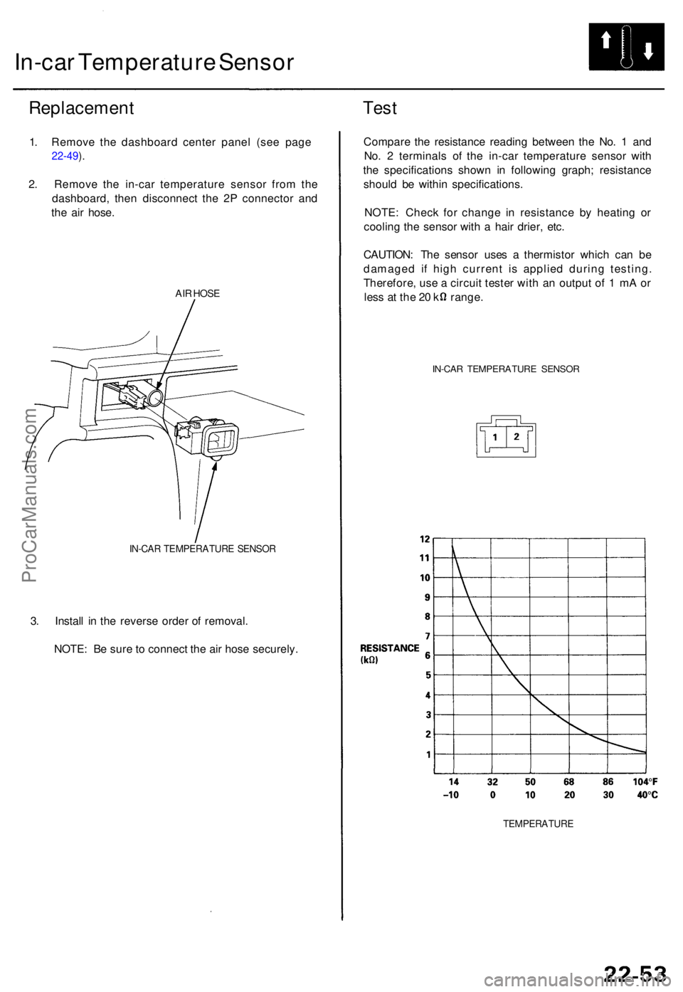
2 . Remov e th e in-ca r temperatur e senso r fro m th e
dashboard , the n disconnec t th e 2 P connecto r an d
th e ai r hose .
AIR HOS E
IN-CA R TEMPERATUR E SENSO R
3. Instal l i n th e revers e orde r o f removal .
NOTE : B e sur e to connec t th e ai r hos e securely .
Test
Compar e th e resistanc e readin g betwee n th e No . 1 an d
No . 2 terminal s o f th e in-ca r temperatur e senso r wit h
th e specification s show n i n followin g graph ; resistanc e
shoul d b e withi n specifications .
NOTE : Chec k fo r chang e i n resistanc e b y heatin g o r
coolin g th e senso r wit h a hai r drier , etc .
CAUTION : Th e senso r use s a thermisto r whic h ca n b e
damage d i f hig h curren t i s applie d durin g testing .
Therefore , us e a circui t teste r wit h a n outpu t o f 1 m A o r
les s a t th e 2 0 k range .
IN-CAR TEMPERATUR E SENSO R
TEMPERATUR E
ProCarManuals.com
Page 1503 of 1771
Outside Ai r Temperatur e Senso r
Replacemen t
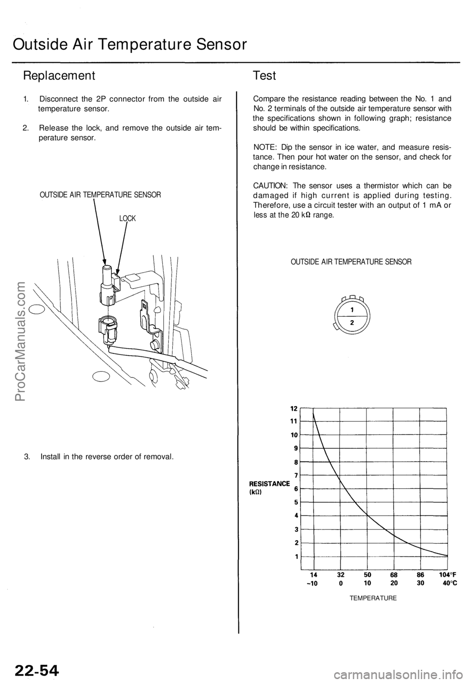
1. Disconnec t th e 2 P connecto r fro m th e outsid e ai r
temperatur e sensor .
2 . Releas e th e lock , an d remov e th e outsid e ai r tem -
peratur e sensor .
OUTSID E AI R TEMPERATUR E SENSO R
LOCK
3. Instal l i n th e revers e orde r o f removal .
Test
Compar e th e resistanc e readin g betwee n th e No . 1 an d
No . 2 terminal s o f th e outsid e ai r temperatur e senso r wit h
th e specification s show n i n followin g graph ; resistanc e
shoul d b e withi n specifications .
NOTE : Di p th e senso r i n ic e water , an d measur e resis -
tance . The n pou r ho t wate r o n th e sensor , an d chec k fo r
chang e in resistance .
CAUTION : Th e senso r use s a thermisto r whic h ca n b e
damage d i f hig h curren t i s applie d durin g testing .
Therefore , us e a circui t teste r wit h a n outpu t o f 1 m A o r
les s a t th e 2 0 k range .
OUTSIDE AI R TEMPERATUR E SENSO R
TEMPERATUR E
ProCarManuals.com
Page 1504 of 1771
Sunlight Sensor
Replacement
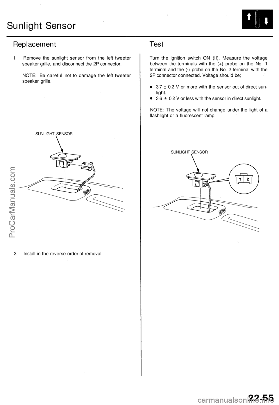
1. Remove the sunlight sensor from the left tweeter
speaker grille, and disconnect the 2P connector.
NOTE: Be careful not to damage the left tweeter
speaker grille.
SUNLIGHT SENSOR
2. Install in the reverse order of removal.
Test
Turn the ignition switch ON (II). Measure the voltage
between the terminals with the (+) probe on the No. 1
terminal and the (-) probe on the No. 2 terminal with the
2P connector connected. Voltage should be;
3.7 ± 0.2 V or more with the sensor out of direct sun-
light.
3.6 ± 0.2 V or less with the sensor in direct sunlight.
NOTE: The voltage will not change under the light of a
flashlight or a fluorescent lamp.
SUNLIGHT SENSORProCarManuals.com
Page 1505 of 1771
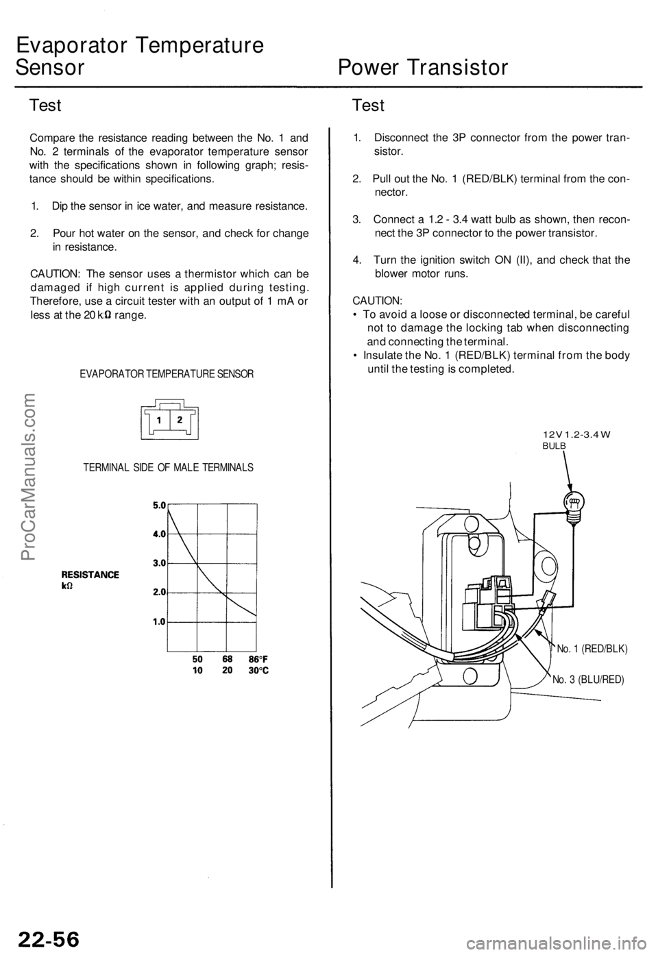
Evaporator Temperatur e
Sensor Powe r Transisto r
TestTes t
Compar e th e resistanc e readin g betwee n th e No . 1 an d
No . 2 terminal s o f th e evaporato r temperatur e senso r
wit h th e specification s show n i n followin g graph ; resis -
tanc e shoul d b e withi n specifications .
1 . Di p th e senso r i n ic e water , an d measur e resistance .
2 . Pou r ho t wate r o n th e sensor , an d chec k fo r chang e
i n resistance .
CAUTION : Th e senso r use s a thermisto r whic h ca n b e
damage d i f hig h curren t i s applie d durin g testing .
Therefore , us e a circui t teste r wit h a n outpu t o f 1 m A o r
les s a t th e 2 0 k range .
EVAPORATO R TEMPERATUR E SENSO R
TERMINA L SID E O F MAL E TERMINAL S
1. Disconnec t th e 3 P connecto r fro m th e powe r tran -
sistor .
2 . Pul l ou t th e No . 1 (RED/BLK ) termina l fro m th e con -
nector .
3. Connec t a 1. 2 - 3. 4 wat t bul b a s shown , the n recon -
nec t th e 3 P connecto r t o th e powe r transistor .
4 . Tur n th e ignitio n switc h O N (II) , an d chec k tha t th e
blowe r moto r runs .
CAUTION :
• T o avoi d a loos e o r disconnecte d terminal , b e carefu l
no t t o damag e th e lockin g ta b whe n disconnectin g
an d connectin g th e terminal .
• Insulat e th e No . 1 (RED/BLK ) termina l fro m th e bod y
unti l th e testin g is completed .
12V 1.2-3. 4 WBUL B
No. 1 (RED/BLK )
No . 3 (BLU/RED )
ProCarManuals.com
Page 1506 of 1771
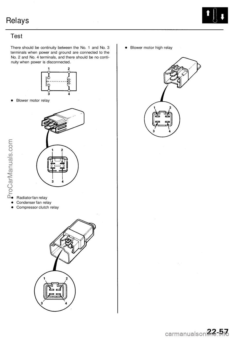
Relays
Test
Ther e shoul d b e continuit y betwee n th e No . 1 an d No . 3
terminal s whe n powe r an d groun d ar e connecte d t o th e
No . 2 an d No . 4 terminals , an d ther e shoul d b e n o conti -
nuit y whe n powe r i s disconnected .
Blowe r moto r rela y
Radiato r fa n rela y
Condense r fa n rela y
Compresso r clutc h rela y Blowe
r moto r hig h rela y
ProCarManuals.com
Page 1507 of 1771
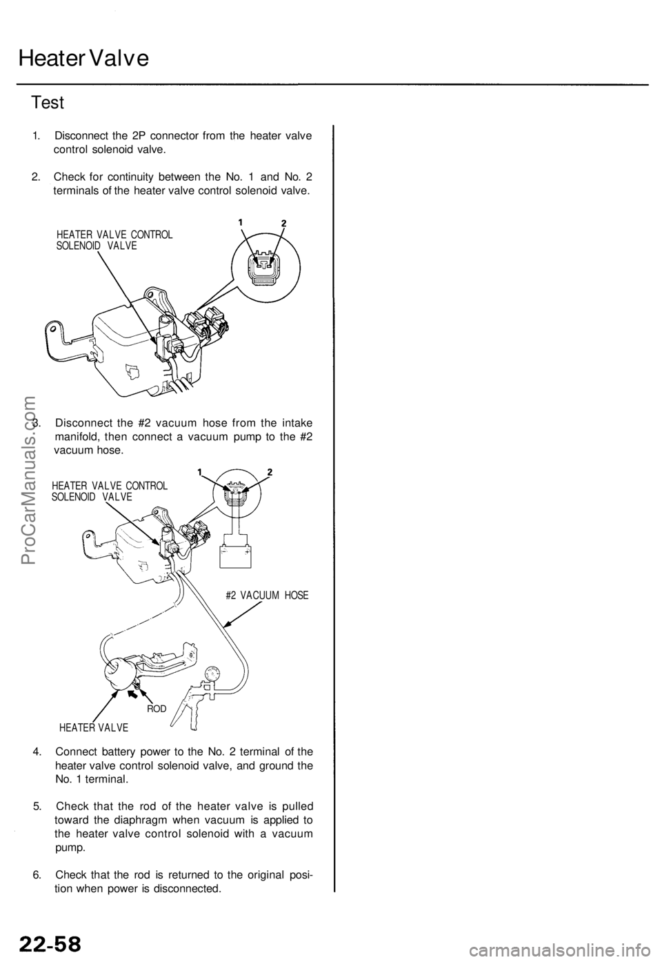
Heater Valve
Test
1. Disconnect the 2P connector from the heater valve
control solenoid valve.
2. Check for continuity between the No. 1 and No. 2
terminals of the heater valve control solenoid valve.
HEATER VALVE CONTROL
SOLENOID VALVE
3. Disconnect the #2 vacuum hose from the intake
manifold, then connect a vacuum pump to the #2
vacuum hose.
HEATER VALVE CONTROL
SOLENOID VALVE
#2 VACUUM HOSE
HEATER VALVE
4. Connect battery power to the No. 2 terminal of the
heater valve control solenoid valve, and ground the
No. 1 terminal.
5. Check that the rod of the heater valve is pulled
toward the diaphragm when vacuum is applied to
the heater valve control solenoid with a vacuum
pump.
6. Check that the rod is returned to the original posi-
tion when power is disconnected.
RODProCarManuals.com
Page 1508 of 1771
Evaporator
Replacemen t
1. Recove r th e refrigeran t wit h a Recovery/Recycling /
Chargin g Syste m (se e pag e 22-71 ).
2 . Remov e th e dashboar d lowe r cover , th e kne e bol -
ste r an d th e glov e bo x (se e sectio n 20 ).
3 . Remov e th e EC M (se e sectio n 11 ).
4 . Remov e th e AB S contro l uni t an d th e radiato r fa n
contro l modul e togethe r wit h th e bracket , the n
remov e th e TC M (se e sectio n 14 ). Remov e th e secu -
rity contro l unit .
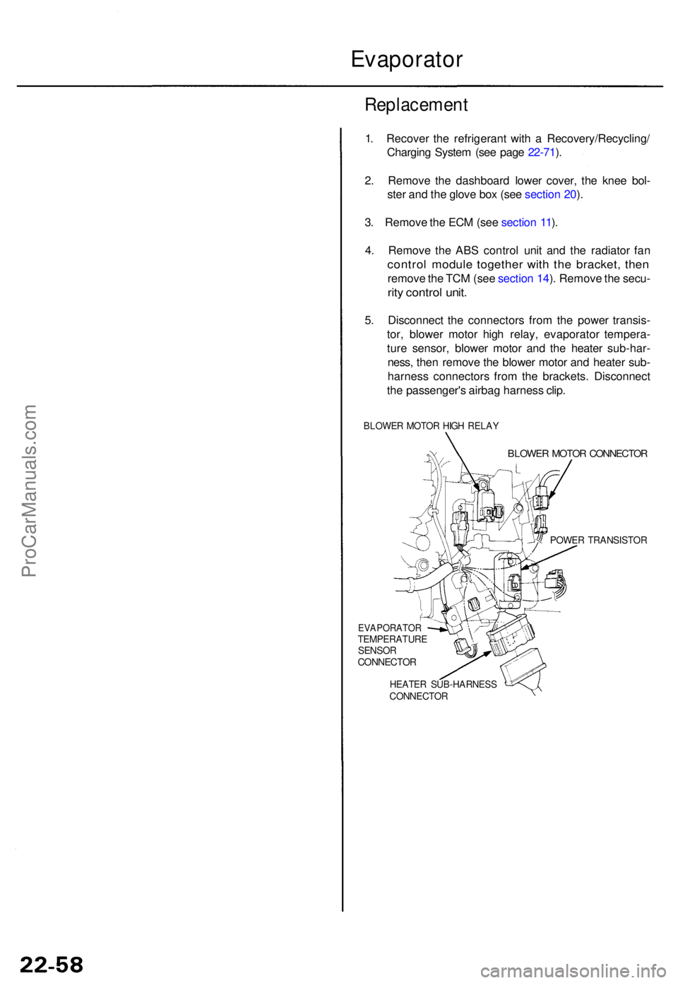
5. Disconnec t th e connector s fro m th e powe r transis -
tor , blowe r moto r hig h relay , evaporato r tempera -
tur e sensor , blowe r moto r an d th e heate r sub-har -
ness , the n remov e th e blowe r moto r an d heate r sub -
harnes s connector s fro m th e brackets . Disconnec t
th e passenger' s airba g harnes s clip .
BLOWE R MOTO R HIG H RELA Y
EVAPORATO RTEMPERATUR ESENSORCONNECTO R
BLOWER MOTO R CONNECTO R
POWER TRANSISTO R
HEATER SUB-HARNES SCONNECTOR
ProCarManuals.com
Page 1509 of 1771
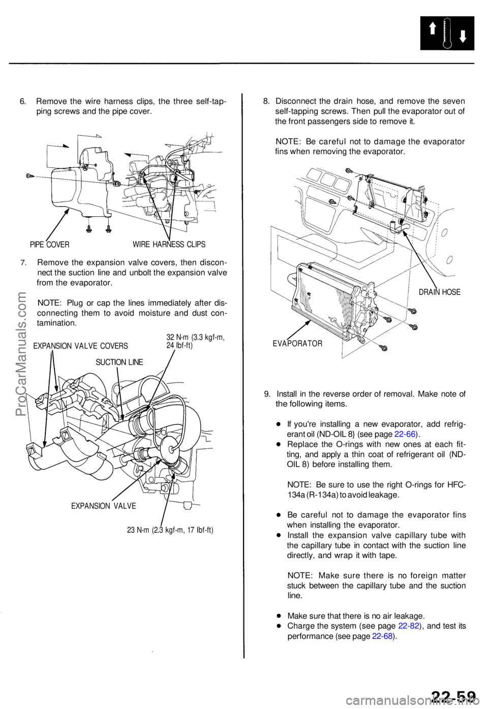
6. Remov e th e wir e harnes s clips , th e thre e self-tap -
pin g screw s an d th e pip e cover .
PIPE COVE R WIR
E HARNES S CLIP S
7.Remov e th e expansio n valv e covers , the n discon -
nec t th e suctio n lin e an d unbol t th e expansio n valv e
fro m th e evaporator .
NOTE : Plu g o r cap the line s immediatel y afte r dis -
connectin g the m to avoi d moistur e an d dus t con -
tamination .
EXPANSIO N VALV E COVER S
SUCTION LIN E
32 N- m (3. 3 kgf-m ,
2 4 Ibf-ft )
EXPANSIO N VALV E
2 3 N- m (2. 3 kgf-m , 1 7 Ibf-ft )
8. Disconnec t th e drai n hose , an d remov e th e seve n
self-tappin g screws . The n pul l th e evaporato r ou t o f
th e fron t passenger s sid e to remov e it .
NOTE : B e carefu l no t t o damag e th e evaporato r
fin s whe n removin g th e evaporator .
DRAIN HOS E
EVAPORATO R
9. Instal l i n th e revers e orde r o f removal . Mak e not e o f
the followin g items .
If you'r e installin g a ne w evaporator, add refrig -
eran t oi l (ND-OI L 8 } (se e pag e 22-66 ).
Replac e th e O-ring s wit h ne w one s a t eac h fit -
ting , an d appl y a thi n coa t o f refrigeran t oi l (ND -
OI L 8 ) befor e installin g them .
NOTE : B e sur e t o us e th e righ t O-ring s fo r HFC -
134 a (R-134a ) t o avoi d leakage .
B e carefu l no t t o damag e th e evaporato r fin s
whe n installin g th e evaporator.
Instal l th e expansio n valv e capillar y tub e wit h
th e capillar y tub e i n contac t wit h th e suctio n lin e
directly , an d wra p i t wit h tape .
NOTE : Mak e sur e ther e i s n o foreig n matte r
stuc k betwee n th e capillar y tub e an d th e suctio n
line.
Mak e sur e tha t ther e is n o ai r leakage .
Charg e th e syste m (se e pag e 22-82 ), an d tes t it s
performanc e (se e pag e 22-68 ).
ProCarManuals.com
Page 1510 of 1771
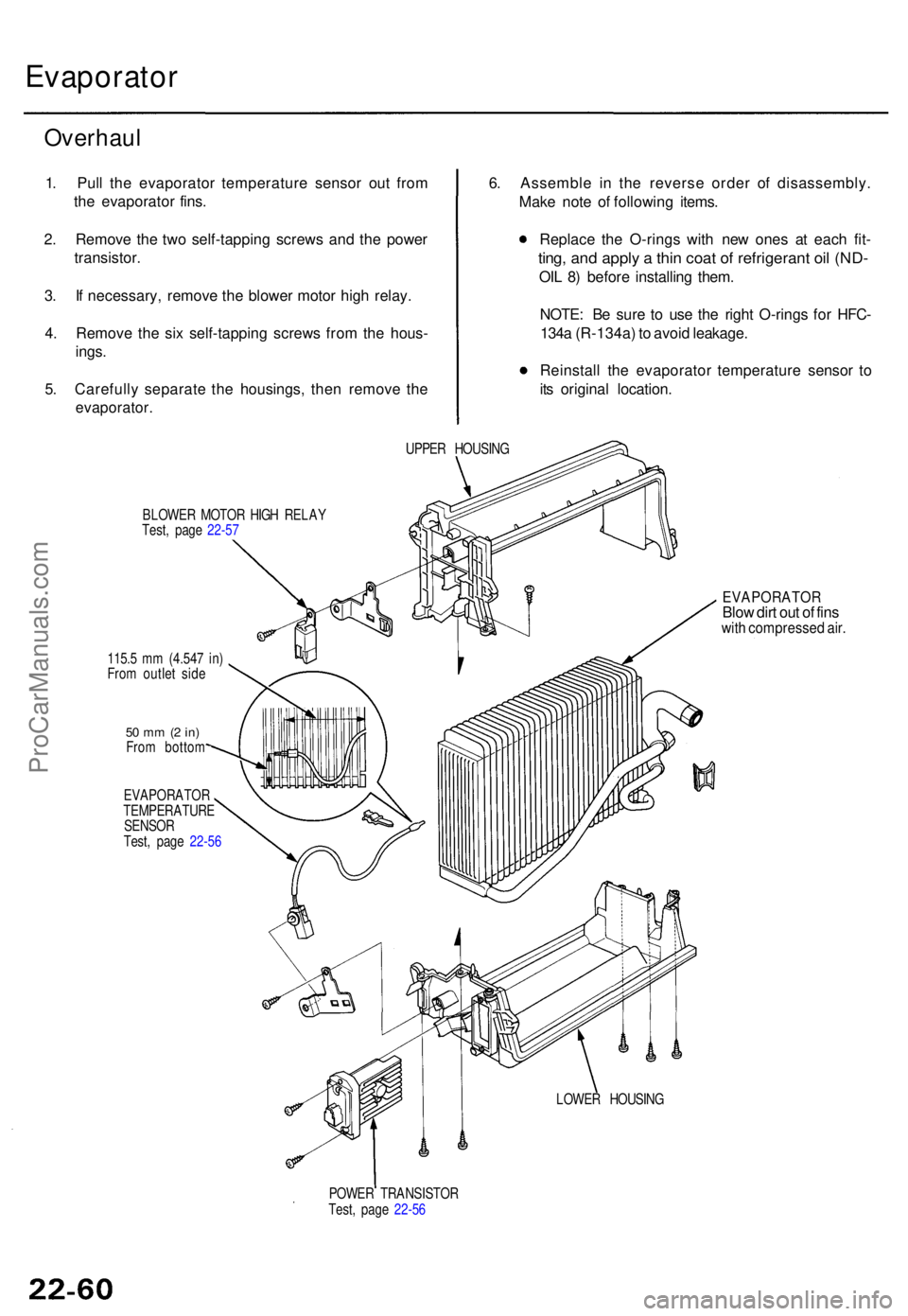
Evaporator
Overhaul
1. Pul l th e evaporato r temperatur e senso r ou t fro m
th e evaporato r fins .
2 . Remov e th e tw o self-tappin g screw s an d th e powe r
transistor .
3 . I f necessary , remov e th e blowe r moto r hig h relay .
4 . Remov e th e si x self-tappin g screw s fro m th e hous -
ings .
5 . Carefull y separat e th e housings , the n remov e th e
evaporator .
6. Assembl e i n th e revers e orde r o f disassembly .
Mak e not e o f followin g items .
Replac e th e O-ring s wit h ne w one s a t eac h fit -
ting , an d appl y a thi n coa t o f refrigeran t oi l (ND -
OIL 8 ) befor e installin g them .
NOTE : B e sur e t o us e th e righ t O-ring s fo r HFC -
134 a (R-134a ) t o avoi d leakage .
Reinstal l th e evaporato r temperatur e senso r t o
it s origina l location .
UPPER HOUSIN G
BLOWE R MOTO R HIG H RELA Y
Test , pag e 22-5 7
115. 5 m m (4.54 7 in )
Fro m outle t sid e
50 m m (2 in )Fro m botto m
EVAPORATO R
TEMPERATUR E
SENSO R
Test , pag e 22-5 6
EVAPORATO RBlow dir t ou t o f fin swit h compresse d air .
LOWE R HOUSIN G
POWE R TRANSISTO R
Test , pag e 22-5 6
ProCarManuals.com