ACURA TL 1995 Service Repair Manual
Manufacturer: ACURA, Model Year: 1995,
Model line: TL,
Model: ACURA TL 1995
Pages: 1771, PDF Size: 62.49 MB
ACURA TL 1995 Service Repair Manual
TL 1995
ACURA
ACURA
https://www.carmanualsonline.info/img/32/56993/w960_56993-0.png
ACURA TL 1995 Service Repair Manual
Trending: display, stop start, Speedometer, boot, key battery, check engine light, coolant capacity
Page 1471 of 1771
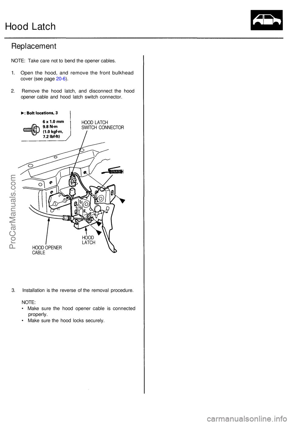
Hood Latc h
Replacemen t
NOTE: Tak e car e no t t o ben d th e opene r cables .
1. Ope n th e hood , an d remov e th e fron t bulkhea d
cover (se e pag e 20-6 ).
2 . Remov e th e hoo d latch , an d disconnec t th e hoo d
opene r cabl e an d hoo d latc h switc h connector .
HOOD LATC H
SWITC H CONNECTO R
HOO D OPENE R
CABLE
3. Installatio n i s th e revers e o f th e remova l procedure .
NOTE :
• Mak e sur e th e hoo d opene r cabl e i s connecte d
properly.
• Mak e sur e th e hoo d lock s securely .
HOODLATC H
ProCarManuals.com
Page 1472 of 1771
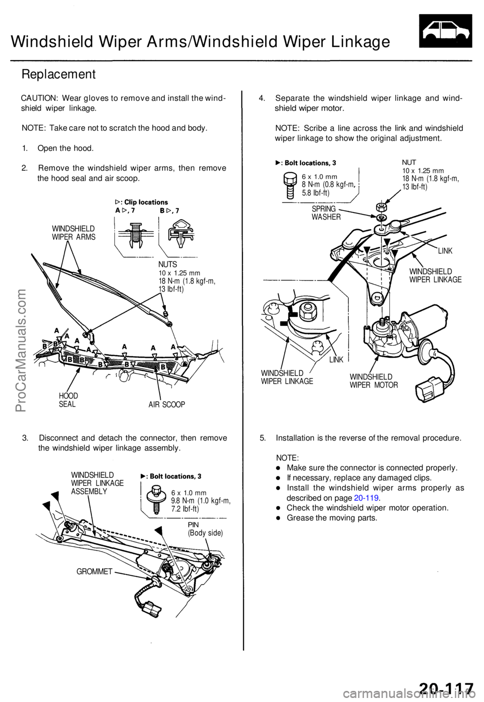
Windshield Wipe r Arms/Windshiel d Wipe r Linkag e
Replacemen t
CAUTION: Wea r glove s to remov e an d instal l th e wind -
shiel d wipe r linkage .
NOTE : Tak e car e no t t o scratc h th e hoo d an d body .
1 . Ope n th e hood .
2 . Remov e th e windshiel d wipe r arms , the n remov e
th e hoo d sea l an d ai r scoop .
WINDSHIEL DWIPER ARM S
NUTS10 x 1.2 5 mm18 N- m (1. 8 kgf-m ,
1 3 Ibf-ft )
HOO D
SEALAIR SCOO P
3. Disconnec t an d detac h th e connector, then remov e
th e windshiel d wipe r linkag e assembly .
GROMMET
4. Separat e th e windshiel d wipe r linkag e an d wind -
shield wipe r motor .
NOTE : Scrib e a lin e acros s th e lin k an d windshiel d
wipe r linkag e t o sho w th e origina l adjustment .
6 x 1. 0 m m8 N- m (0. 8 kgf- m
5. 8 Ibf-ft )
NUT10 x 1.2 5 mm18 N- m (1. 8 kgf-m ,
1 3 Ibf-ft )
WINDSHIEL DWIPER LINKAG E
WINDSHIEL DWIPER LINKAG E
5. Installatio n is th e revers e o f th e remova l procedure .
NOTE:
Make sur e th e connecto r i s connecte d properly .
I f necessary , replac e an y damage d clips .
Instal l th e windshiel d wipe r arm s properl y a s
describe d o n pag e 20-119 .
Chec k th e windshiel d wipe r moto r operation .
Greas e th e movin g parts .
6 x 1. 0 m m9.8 N- m (1. 0 kgf-m ,
7. 2 Ibf-ft )
WINDSHIEL DWIPER LINKAG E
ASSEMBL Y
WINDSHIEL DWIPER MOTO R
LIN
K
LIN K
SPRIN G
WASHE R
PIN(Bod y side )
ProCarManuals.com
Page 1473 of 1771
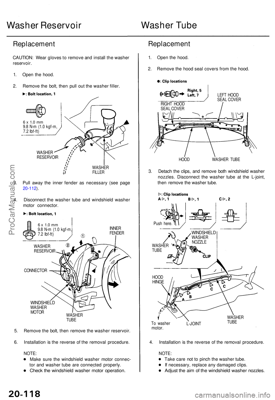
Washer Reservoi r Washe
r Tub e
Replacemen t
CAUTION: Wea r glove s to remov e an d instal l th e washe r
reservoir .
1. Ope n th e hood .
2 . Remov e th e bolt , the n pul l ou t th e washe r filler .
6 x 1. 0 m m9.8 N- m (1. 0 kgf-m ,
7. 2 Ibf-ft )
WASHE R
RESERVOI R
WASHER
FILLER
3. Pul l awa y th e inne r fende r a s necessar y (se e pag e
20-112 ).
4 . Disconnec t th e washe r tub e an d windshiel d washe r
moto r connector .
INNERFENDE R
CONNECTO R
WINDSHIELDWASHER
MOTO R
WASHER
TUB E
5. Remov e th e bolt , the n remov e th e washe r reservoir .
6 . Installatio n i s th e revers e o f th e remova l procedure .
NOTE:
Make sur e th e windshiel d washe r moto r connec -
to r an d washe r tub e ar e connecte d properly .
Check th e windshiel d washe r moto r operation .
Replacemen t
1. Ope n th e hood .
2 . Remov e th e hoo d sea l cover s fro m th e hood .
LEFT HOO D
SEA L COVE R
HOO D WASHER TUB E
3. Detac h th e clips , an d remov e bot h windshiel d washe r
nozzles . Disconnec t th e washe r tub e a t th e L-joint ,
the n remov e th e washe r tube .
WINDSHIEL DWASHER
NOZZL E
T o washe r
motor.L-JOIN T
WASHE R
TUB E
4. Installatio n i s th e revers e o f th e remova l procedure .
NOTE:
Take car e no t t o pinc h th e washe r tube .
I f necessary , replac e an y damage d clips .
Adjus t th e ai m o f th e windshiel d washe r nozzles .
RIGHT HOO D
SEA L COVE R
Pus h here .
WASHE R
TUB E
HOO D
HING E
6 x 1. 0 m m9.8 N- m (1. 0 kgf-m ,
7. 2 Ibf-ft )
WASHE R
RESERVOI R
ProCarManuals.com
Page 1474 of 1771
Wiper Arms/Washe r Nozzle s
Adjustmen t
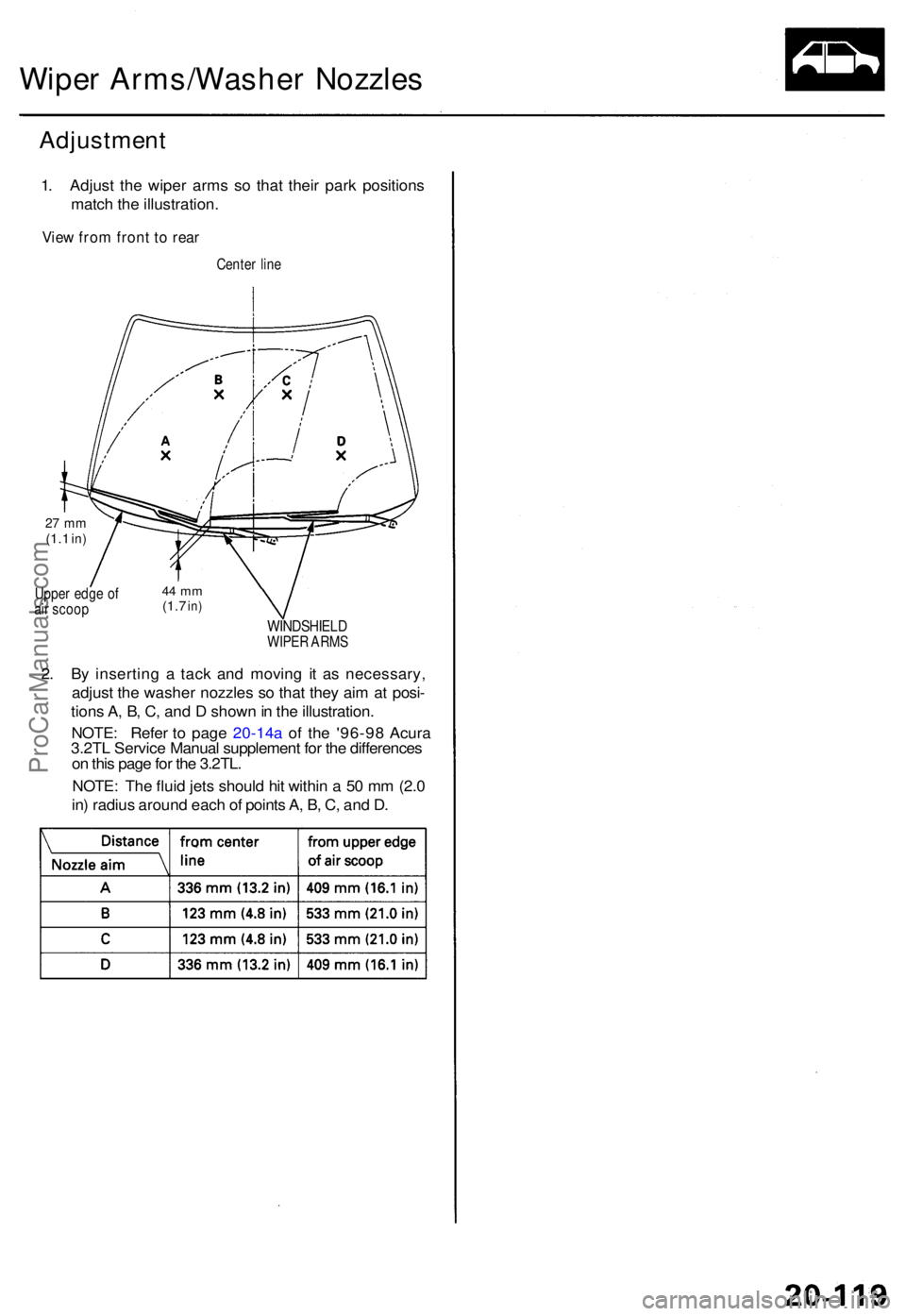
1. Adjus t th e wipe r arm s s o tha t thei r par k position s
matc h th e illustration .
View fro m fron t t o rea r
Cente r lin e
27 m m(1.1 in)
Uppe r edg e o f
ai r scoo p44 m m(1.7 in)
WINDSHIEL DWIPER ARM S
2. B y insertin g a tac k an d movin g i t a s necessary ,
adjus t th e washe r nozzle s s o tha t the y ai m a t posi -
tion s A , B , C , an d D show n in th e illustration .
NOTE : Th e flui d jet s shoul d hi t withi n a 5 0 m m (2. 0
in ) radiu s aroun d eac h o f point s A , B , C , an d D .
NOTE : Refe r t o page 20-14a of th e '96-9 8 Acura 3.2TL Servic e Manual supplement for the differences on this page for the 3.2TL.
ProCarManuals.com
Page 1475 of 1771
Emblems
Installatio n
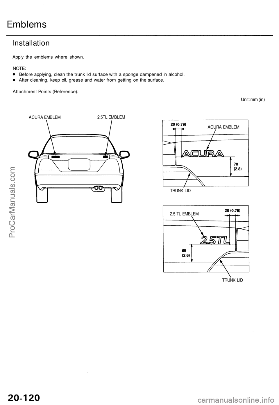
Apply th e emblem s wher e shown .
NOTE:
Before applying , clea n th e trun k li d surfac e wit h a spong e dampene d i n alcohol .
Afte r cleaning , kee p oil , greas e an d wate r fro m gettin g o n th e surface .
Attachmen t Point s (Reference) :
Unit: m m (in )
ACUR A EMBLE M 2.5T
L EMBLE M
TRUNK LI D
TRUNK LI D
2.
5 T L EMBLE MACUR
A EMBLE M
ProCarManuals.com
Page 1476 of 1771
Sub-frame
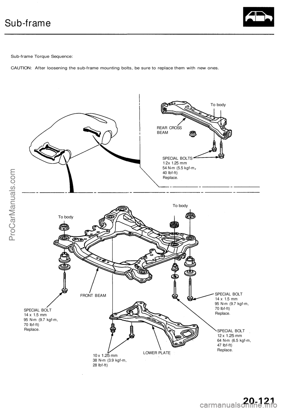
Sub-frame Torque Sequence:
CAUTION: After loosening the sub-frame mounting bolts, be sure to replace them with new ones.
To body
REAR CROSS
BEAM
SPECIAL BOLTS
1 2x
1.25
mm
54 N-m (5.5 kgf-m,
40 Ibf-ft)
Replace.
To body
To body
SPECIAL BOLT
14 x 1.5 mm
95 N-m (9.7 kgf-m,
70 Ibf-ft)
Replace.
10 x
1.25
mm
38 N-m (3.9 kgf-m,
28 Ibf-ft)
LOWER PLATE
SPECIAL BOLT
14 x 1.5 mm
95 N-m (9.7 kgf-m,
70 Ibf-ft)
Replace.
SPECIAL BOLT
12 x
1.25
mm
64 N-m (6.5 kgf-m,
47 Ibf-ft)
Replace.
FRONT BEAMProCarManuals.com
Page 1477 of 1771
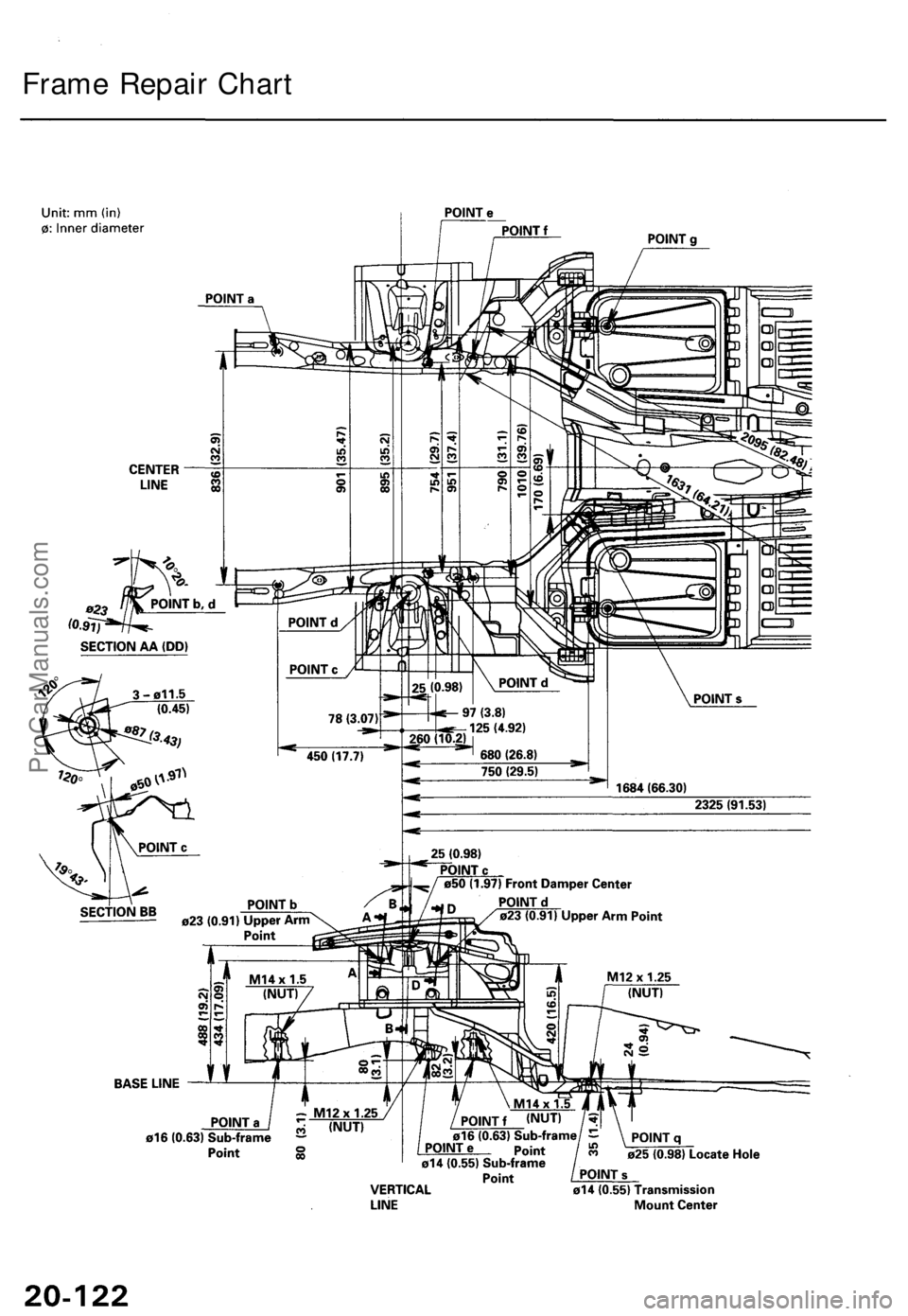
Frame Repair ChartProCarManuals.com
Page 1478 of 1771
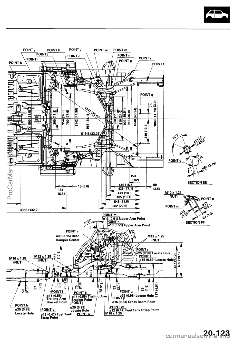
POINT y
POINT vProCarManuals.com
Page 1479 of 1771
Mirror
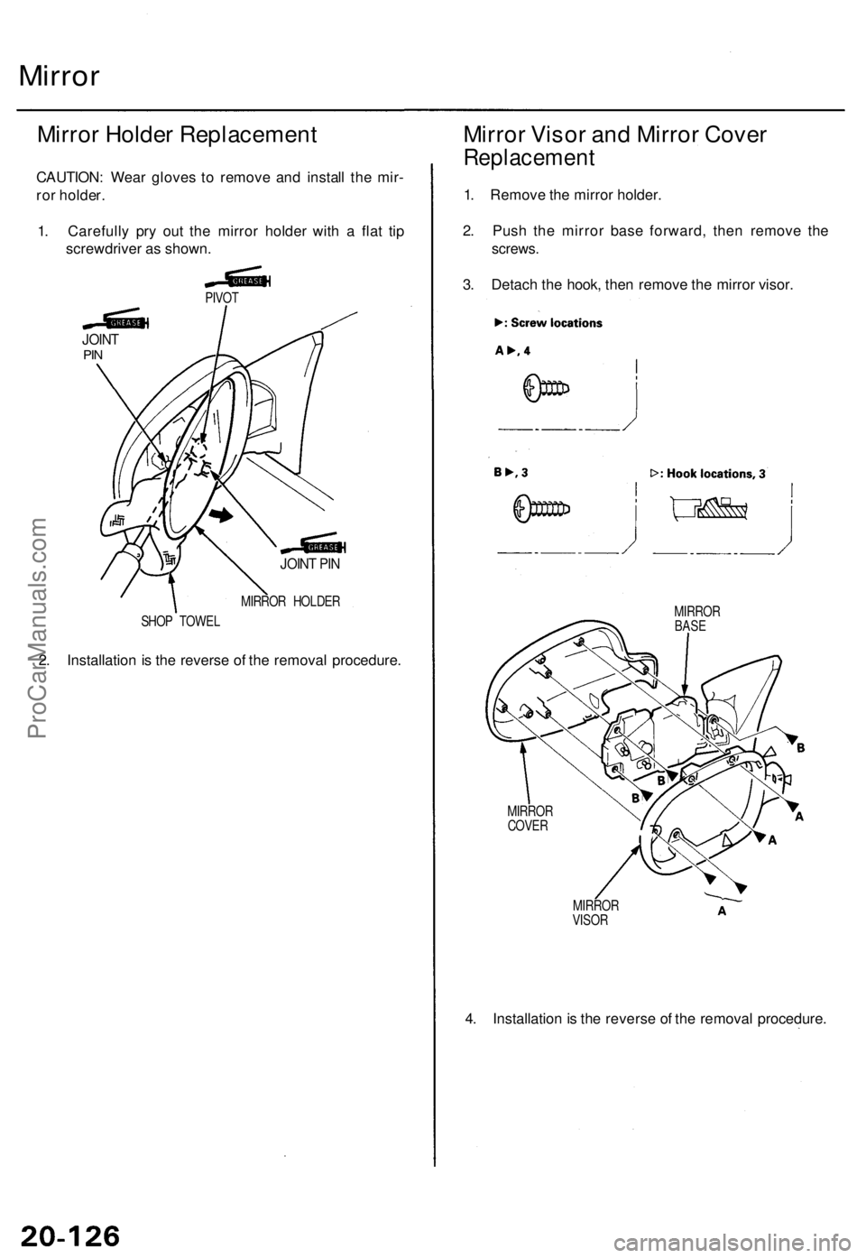
Mirror Holde r Replacemen t
CAUTION: Wea r glove s t o remov e an d instal l th e mir -
ro r holder .
1 . Carefull y pr y ou t th e mirro r holde r wit h a fla t ti p
screwdrive r a s shown .
PIVOT
JOINT PI N
MIRRO R HOLDE R
SHO P TOWE L
2. Installatio n is th e revers e o f th e remova l procedure .
Mirror Viso r an d Mirro r Cove r
Replacemen t
1. Remov e th e mirro r holder .
2 . Pus h th e mirro r bas e forward , the n remov e th e
screws .
3. Detac h th e hook , the n remov e th e mirro r visor .
MIRRO RBASE
MIRRO RCOVER
MIRRO R
VISO R
4. Installatio n is th e revers e o f th e remova l procedure .
JOINTPIN
ProCarManuals.com
Page 1480 of 1771
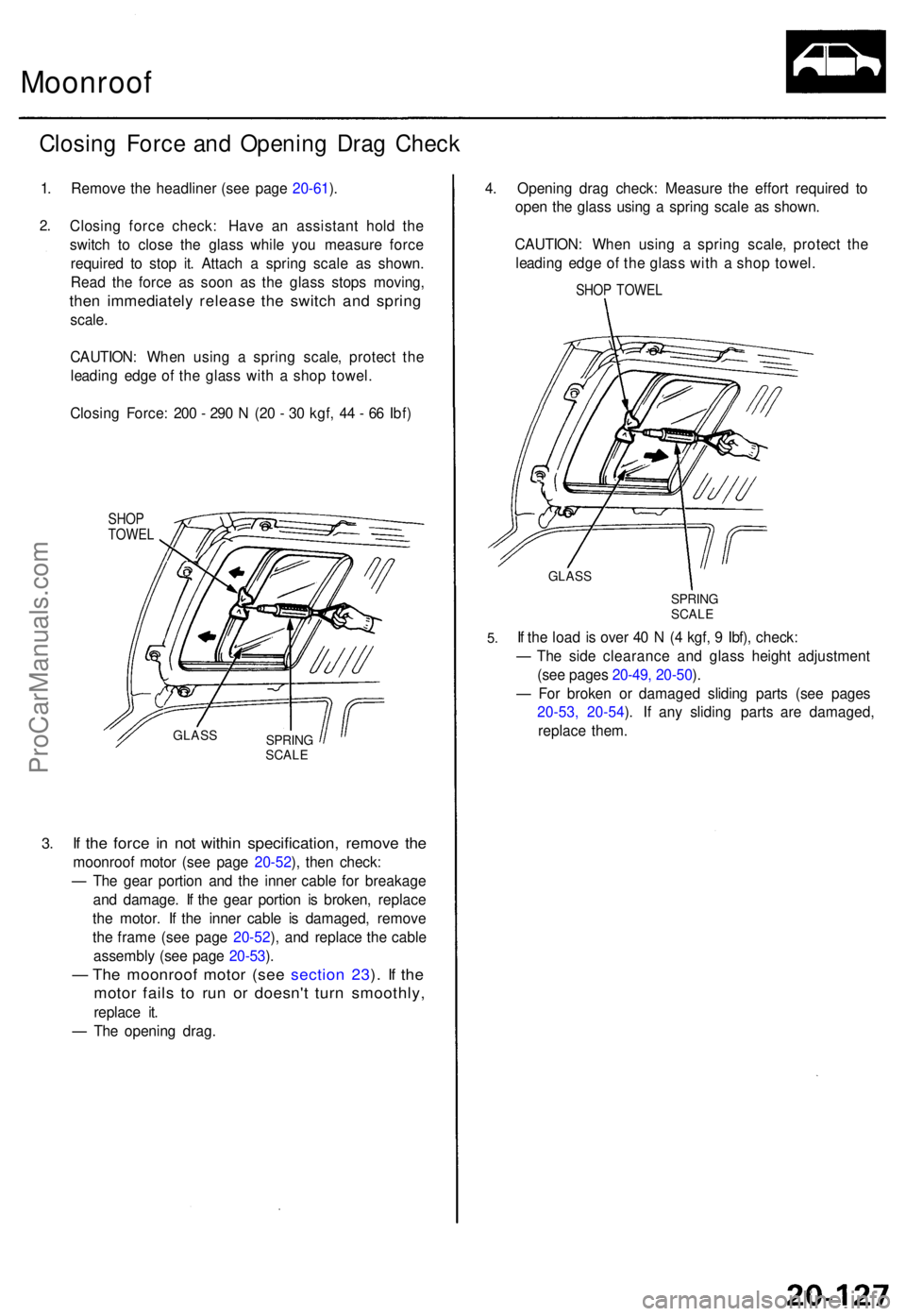
Moonroof
Closing Forc e an d Openin g Dra g Chec k
1. Remov e th e headline r (se e pag e 20-61 ).
2 .
3.
Closin g forc e check : Hav e a n assistan t hol d th e
switc h t o clos e th e glas s whil e yo u measur e forc e
require d t o sto p it . Attac h a sprin g scal e a s shown .
Rea d th e forc e a s soo n a s th e glas s stop s moving ,
then immediatel y releas e th e switc h an d sprin g
scale.
CAUTION : Whe n usin g a sprin g scale , protec t th e
leadin g edg e o f th e glas s wit h a sho p towel .
Closin g Force : 20 0 - 29 0 N (2 0 - 3 0 kgf , 4 4 - 6 6 Ibf )
SHO PTOWE L
If th e forc e i n no t withi n specification , remov e th e
moonroo f moto r (se e pag e 20-52 ), the n check :
— Th e gea r portio n an d th e inne r cabl e fo r breakag e
an d damage . I f th e gea r portio n i s broken , replac e
th e motor . I f th e inne r cabl e i s damaged , remov e
th e fram e (se e pag e 20-52 ), an d replac e th e cabl e
assembl y (se e pag e 20-53 ).
— Th e moonroo f moto r (se e sectio n 23 ). I f th e
moto r fail s t o ru n o r doesn' t tur n smoothly ,
replace it .
— Th e openin g drag . 4
. Openin g dra g check : Measur e th e effor t require d t o
ope n th e glas s usin g a sprin g scal e a s shown .
CAUTION : Whe n usin g a sprin g scale , protec t th e
leadin g edg e o f th e glas s wit h a sho p towel .
SHOP TOWE L
GLASS
SPRIN GSCALE
5.If th e loa d i s ove r 4 0 N (4 kgf , 9 Ibf) , check :
— Th e sid e clearanc e an d glas s heigh t adjustmen t
(se e page s 20-49 , 20-50 ).
— Fo r broke n o r damage d slidin g part s (se e page s
20-53, 20-54 ). If any sliding parts are damaged,
replac e them .
SPRIN GSCALE
GLAS S
ProCarManuals.com
Trending: dimensions, engine oil, jump cable, radio controls, roof, high beam, oil filter
