Alfa Romeo Giulietta 2013 Owner handbook (in English)
Manufacturer: ALFA ROMEO, Model Year: 2013, Model line: Giulietta, Model: Alfa Romeo Giulietta 2013Pages: 292, PDF Size: 13.06 MB
Page 161 of 292
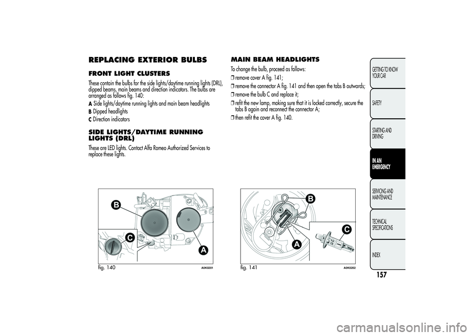
REPLACING EXTERIOR BULBSFRONT LIGHT CLUSTERSThese contain the bulbs for the side lights/daytime running lights (DRL),
dipped beams, main beams and direction indicators. The bulbs are
arranged as follows fig. 140:ASide lights/daytime running lights and main beam headlightsBDipped headlightsCDirection indicatorsSIDE LIGHTS/DAYTIME RUNNING
LIGHTS (DRL)These are LED lights. Contact Alfa Romeo Authorized Services to
replace these lights.
MAIN BEAM HEADLIGHTSTo change the bulb, proceed as follows:
❒remove cover A fig. 141;
❒remove the connector A fig. 141 and then open the tabs B outwards;
❒remove the bulb C and replace it;
❒refit the new lamp, making sure that it is locked correctly, secure the
tabs B again and reconnect the connector A;
❒then refit the cover A fig. 140.
fig. 140
A0K0201
fig. 141
A0K0202
157GETTING TO KNOW
YOUR CAR
SAFETY
STARTING AND
DRIVINGIN AN
EMERGENCYSERVICING AND
MAINTENANCE
TECHNICAL
SPECIFICATIONS
INDEX
Page 162 of 292
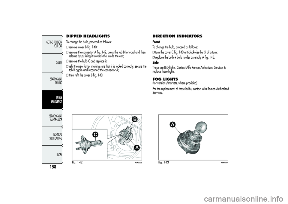
DIPPED HEADLIGHTSTo change the bulb, proceed as follows:
❒remove cover B fig. 140;
❒remove the connector A fig. 142, press the tab B forward and then
release by pushing it towards the inside the car;
❒remove the bulb C and replace it;
❒refit the new lamp, making sure that it is locked correctly, secure the
tab B again and reconnect the connector A;
❒then refit the cover B fig. 140.
DIRECTION INDICATORSFront
To change the bulb, proceed as follows:
❒turn the cover C fig. 140 anticlockwise by ¼ of a turn;
❒replace the bulb + bulb holder assembly A fig. 143.
Side
These are LED lights. Contact Alfa Romeo Authorized Services to
replace these lights.FOG LIGHTS(for versions/markets, where provided)
For the replacement of these bulbs, contact Alfa Romeo Authorized
Services.
fig. 142
A0K0203
fig. 143
A0K0204
158GETTING TO KNOW
YOUR CAR
SAFETY
STARTING AND
DRIVING
IN AN
EMERGENCY
SERVICING AND
MAINTENANCE
TECHNICAL
SPECIFICATIONS
INDEX
Page 163 of 292
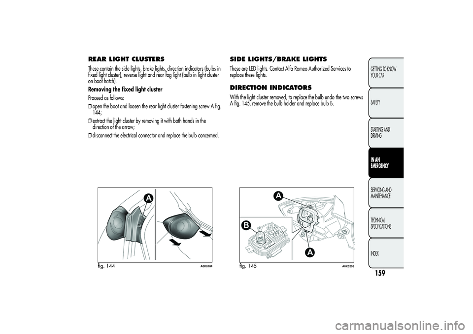
REAR LIGHT CLUSTERSThese contain the side lights, brake lights, direction indicators (bulbs in
fixed light cluster), reverse light and rear fog light (bulb in light cluster
on boot hatch).
Removing the fixed light cluster
Proceed as follows:
❒open the boot and loosen the rear light cluster fastening screw A fig.
144;
❒extract the light cluster by removing it with both hands in the
direction of the arrow;
❒disconnect the electrical connector and replace the bulb concerned.
SIDE LIGHTS/BRAKE LIGHTSThese are LED lights. Contact Alfa Romeo Authorized Services to
replace these lights.DIRECTION INDICATORSWith the light cluster removed, to replace the bulb undo the two screws
A fig. 145, remove the bulb holder and replace bulb B.
fig. 144
A0K0184
fig. 145
A0K0205
159GETTING TO KNOW
YOUR CAR
SAFETY
STARTING AND
DRIVINGIN AN
EMERGENCYSERVICING AND
MAINTENANCE
TECHNICAL
SPECIFICATIONS
INDEX
Page 164 of 292
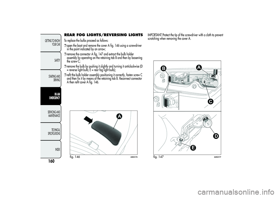
REAR FOG LIGHTS/REVERSING LIGHTSTo replace the bulbs proceed as follows:
❒open the boot and remove the cover A fig. 146 using a screwdriver
in the point indicated by an arrow;
❒remove the connector A fig. 147 and extract the bulb holder
assembly by operating on the retaining tab B and then by loosening
the screw C;
❒remove the bulb by pushing it slightly and turning it anticlockwise (D
= reverse light bulb; E = rear fog light bulb);
❒refit the bulb holder assembly positioning it correctly, fasten screw C
and then fix it by means of the retaining tab B. Reconnect connector
A then refit cover A fig. 146.IMPORTANT Protect the tip of the screwdriver with a cloth to prevent
scratching when removing the cover A.
fig. 146
A0K0176
fig. 147
A0K0177
160GETTING TO KNOW
YOUR CAR
SAFETY
STARTING AND
DRIVING
IN AN
EMERGENCY
SERVICING AND
MAINTENANCE
TECHNICAL
SPECIFICATIONS
INDEX
Page 165 of 292
3rd
BRAKE LIGHTS
These are LED lights and are located on the spoiler integrated with the
tailgate. Contact Alfa Romeo Authorized Services to replace these
lights.
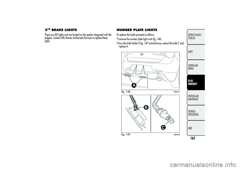
NUMBER PLATE LIGHTSTo replace the bulbs proceed as follows:
❒remove the number plate light units fig. 148;
❒turn the bulb holder B fig. 149 anticlockwise, extract the bulb C and
replace it;
fig. 148
A0K0147
fig. 149
A0K0146
161GETTING TO KNOW
YOUR CAR
SAFETY
STARTING AND
DRIVINGIN AN
EMERGENCYSERVICING AND
MAINTENANCE
TECHNICAL
SPECIFICATIONS
INDEX
Page 166 of 292
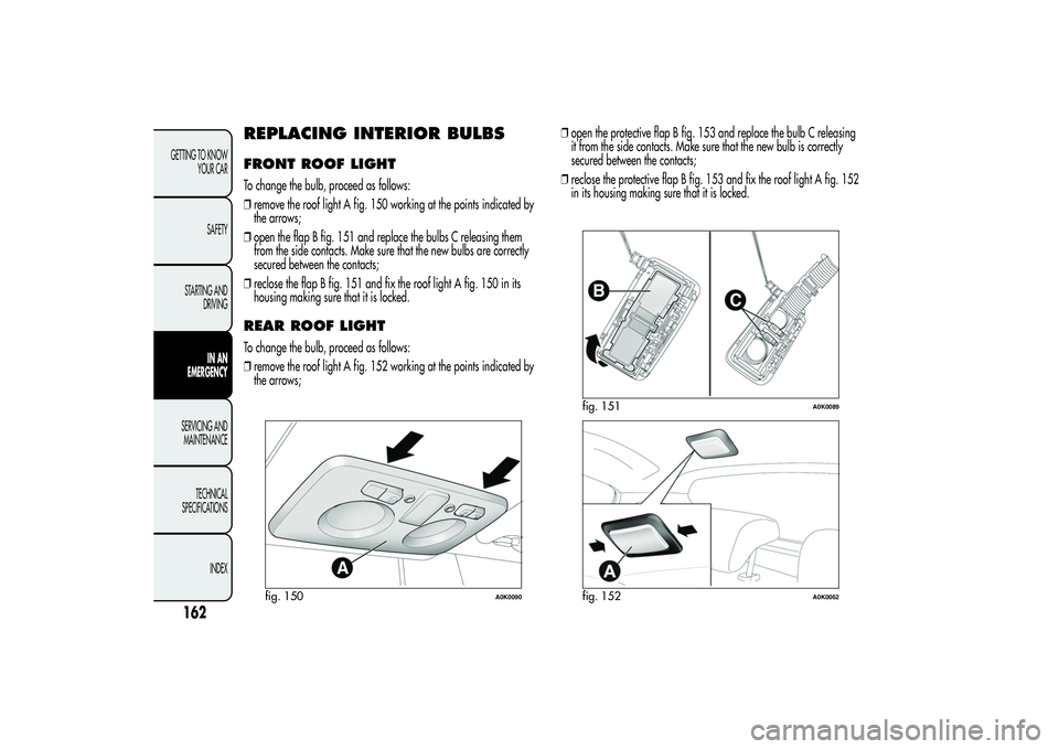
REPLACING INTERIOR BULBSFRONT ROOF LIGHTTo change the bulb, proceed as follows:
❒remove the roof light A fig. 150 working at the points indicated by
the arrows;
❒open the flap B fig. 151 and replace the bulbs C releasing them
from the side contacts. Make sure that the new bulbs are correctly
secured between the contacts;
❒reclose the flap B fig. 151 and fix the roof light A fig. 150 in its
housing making sure that it is locked.REAR ROOF LIGHTTo change the bulb, proceed as follows:
❒remove the roof light A fig. 152 working at the points indicated by
the arrows;❒open the protective flap B fig. 153 and replace the bulb C releasing
it from the side contacts. Make sure that the new bulb is correctly
secured between the contacts;
❒reclose the protective flap B fig. 153 and fix the roof light A fig. 152
in its housing making sure that it is locked.
fig. 150
A0K0090
fig. 151
A0K0089
fig. 152
A0K0062
162GETTING TO KNOW
YOUR CAR
SAFETY
STARTING AND
DRIVING
IN AN
EMERGENCY
SERVICING AND
MAINTENANCE
TECHNICAL
SPECIFICATIONS
INDEX
Page 167 of 292
LUGGAGE COMPARTMENT
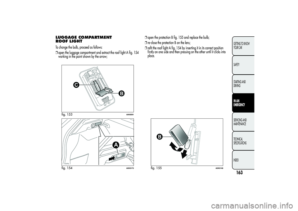
ROOF LIGHTTo change the bulb, proceed as follows:
❒open the luggage compartment and extract the roof light A fig. 154
working in the point shown by the arrow;❒open the protection B fig. 155 and replace the bulb;
❒re-close the protection B on the lens;
❒refit the roof light A fig. 154 by inserting it in its correct position
firstly on one side and then pressing on the other until it clicks into
place.
fig. 153
A0K0091
fig. 154
A0K0173
fig. 155
A0K0148
163GETTING TO KNOW
YOUR CAR
SAFETY
STARTING AND
DRIVINGIN AN
EMERGENCYSERVICING AND
MAINTENANCE
TECHNICAL
SPECIFICATIONS
INDEX
Page 168 of 292
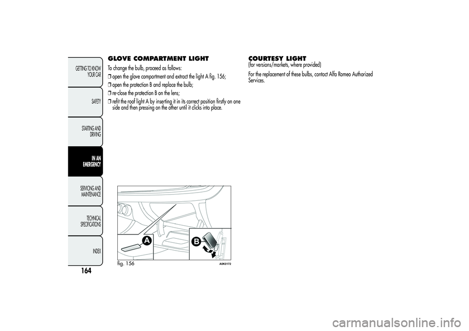
GLOVE COMPARTMENT LIGHTTo change the bulb, proceed as follows:
❒open the glove compartment and extract the light A fig. 156;
❒open the protection B and replace the bulb;
❒re-close the protection B on the lens;
❒refit the roof light A by inserting it in its correct position firstly on one
side and then pressing on the other until it clicks into place.
COURTESY LIGHT(for versions/markets, where provided)
For the replacement of these bulbs, contact Alfa Romeo Authorized
Services.
fig. 156
A0K0172
164GETTING TO KNOW
YOUR CAR
SAFETY
STARTING AND
DRIVING
IN AN
EMERGENCY
SERVICING AND
MAINTENANCE
TECHNICAL
SPECIFICATIONS
INDEX
Page 169 of 292
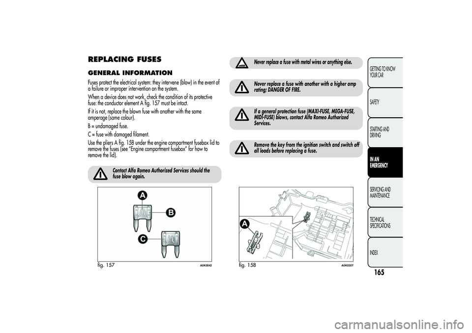
REPLACING FUSESGENERAL INFORMATIONFuses protect the electrical system: they intervene (blow) in the event of
a failure or improper intervention on the system.
When a device does not work, check the condition of its protective
fuse: the conductor element A fig. 157 must be intact.
If it is not, replace the blown fuse with another with the same
amperage (same colour).
B = undamaged fuse.
C = fuse with damaged filament.
Use the pliers A fig. 158 under the engine compartment fusebox lid to
remove the fuses (see “Engine compartment fusebox” for how to
remove the lid).
Contact Alfa Romeo Authorized Services should the
fuse blow again.
Never replace a fuse with metal wires or anything else.Never replace a fuse with another with a higher amp
rating; DANGER OF FIRE.If a general protection fuse (MAXI-FUSE, MEGA-FUSE,
MIDI-FUSE) blows, contact Alfa Romeo Authorized
Services.Remove the key from the ignition switch and switch off
all loads before replacing a fuse.
fig. 157
A0K0042
fig. 158
A0K0207
165GETTING TO KNOW
YOUR CAR
SAFETY
STARTING AND
DRIVINGIN AN
EMERGENCYSERVICING AND
MAINTENANCE
TECHNICAL
SPECIFICATIONS
INDEX
Page 170 of 292
Contact Alfa Romeo Authorized Services if a safety
system (air bags, brakes), engine system (engine,
gearbox) or steering system general protection fuse
blows.
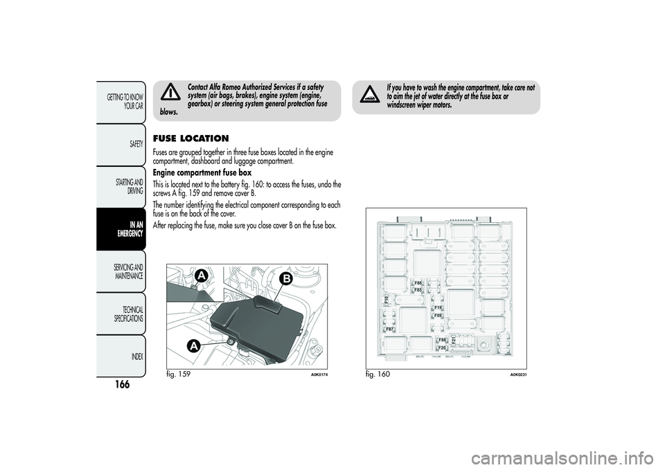
FUSE LOCATIONFuses are grouped together in three fuse boxes located in the engine
compartment, dashboard and luggage compartment.
Engine compartment fuse box
This is located next to the battery fig. 160: to access the fuses, undo the
screws A fig. 159 and remove cover B.
The number identifying the electrical component corresponding to each
fuse is on the back of the cover.
After replacing the fuse, make sure you close cover B on the fuse box.
If you have to wash the engine compartment, take care not
to aim the jet of water directly at the fuse box or
windscreen wiper motors.
fig. 159
A0K0174
fig. 160
A0K0231
166GETTING TO KNOW
YOUR CAR
SAFETY
STARTING AND
DRIVING
IN AN
EMERGENCY
SERVICING AND
MAINTENANCE
TECHNICAL
SPECIFICATIONS
INDEX