DATSUN 210 1979 Service Manual
Manufacturer: DATSUN, Model Year: 1979, Model line: 210, Model: DATSUN 210 1979Pages: 548, PDF Size: 28.66 MB
Page 501 of 548

Condition
Insufficient
heating
performance
No
heated
air
discharged
Insufficient
air
flow
to
floor
Insufficient
defrosting
performance
Cold
air
discharged
Insufficient
air
flow
to
defroster
Heated
air
discharged
with
lever
in
VENT
Blower
motor
does
not
run
Control
lever
drags
Outside
air
comes
in
with
fan
in
OFF
Noise
frol11
blower
motor
Body
Electrical
System
Probable
cause
Cooling
water
temperature
too
low
Heater
core
plugged
Insufficient
cooling
water
level
Malfunctioning
air
mix
door
Malfunctioning
water
cock
Blower
motor
speed
too
low
Malfunctioning
floor
door
Refer
to
No
heated
air
discharged
Malfunctioning
hoor
door
or
faulty
seal
Defroster
nozzle
plugged
Leak
at
defroster
duct
lo
nozzle
connection
Water
cock
not
operating
properly
Mode
door
not
operating
properly
or
seal
damaged
Fuse
melted
MOlor
wire
connector
disconnected
Faulty
switch
Faulty
motor
Faultyblower
control
amplifier
Inner
wire
rubbing
against
outer
case
end
Control
cable
bent
excessively
Malfunctioniilg
doors
door
levers
etc
Air
intake
door
not
operating
properly
Control
cable
out
of
adjustment
Loose
bolt
in
blower
motor
BE
56
Corrective
action
Check
thermostat
Rep1ace
as
nece
ry
Clean
Rem
Adjust
control
cable
Adjust
control
cable
Check
motor
terminal
voltage
Repair
poor
connection
and
discontinuity
Replace
motor
if
necessary
Replace
blower
control
amplifier
if
neces
sary
Adjust
control
cable
Adjust
control
cable
Clean
Correcl
Adjust
control
cable
Adjust
control
cable
Correct
cause
and
replace
qrrect
Replace
Check
and
correct
Replace
Adjust
control
cable
Correct
Ch
ck
and
COrrect
Repair
or
replace
Adjust
control
cable
Check
and
tighten
loose
bolts
Page 502 of 548
DATSUN
210
Model
8310
Series
SECTIONAC
AIR
CONDITIONING
CONTENTS
DESCRIPTION
OUTLINE
OF
AIR
CONDITIONER
REFRIGERATION
SYSTEM
AIR
FLOW
VACUUM
SYSTEM
ELECTRICAL
CIRCUIT
GENERAL
SERVICE
REFRIGERANT
R
12
COMPRESSOR
OIL
MAINTENANCE
GENERAL
SERVICE
INSTRUCTIONS
SAFETY
PRECAUTIONS
EVACUATING
AND
CHARGING
SYSTEM
CHECKI
NG
FOR
LEAKS
REFRIGERANT
LEVEL
CHECK
COMPRESSOR
OIL
LEVEL
OHECK
PERFORMANCE
TEST
REFRIGERANT
LEAKS
SERVICE
PROCEDURES
FAST
IDLE
ACTUATOR
IDL
E
PULLEY
AND
COMPRESSOR
DRIVE
BELT
COMPR
ESSOR
CONDENSER
RECEIV
ER
DRIER
REFRIGERANT
LINES
I
COOLING
UNIT
EXPANSION
VALVE
THERMOSTAT
MAIN
RELAY
HEATER
UNIT
WATER
COCK
AC
2
AC
2
AC
3
AC
5
AC
6
AC
7
AC
9
AC
9
AC
9
AC
9
AC
9
AC
9
AC
1
AC14
AC15
AC
17
AC17
AC17
AC18
AC1B
AC19
AC19
AC
20
AC
20
AC
21
ACc21
AC
22
AC
22
AC
23
AC
23
AC
23
BLOWER
MOTOR
RESISTOR
AIR
CONDITIONER
CONTROL
FAN
SWITCH
MICROSWITCH
LOW
PRESSURE
SWITCH
MAGNET
VALVE
FUSE
REPLACEMENT
VACUUM
HOSE
DIAGRAM
WIRING
DIAGRAM
COMPRESSOR
MODEL
SC206
PRELIMINARY
CLEANING
COMPRESSOR
CLUTCH
SHAFT
SEAL
CYLINDER
HEAD
AND
VALVE
PLATE
DISCHARGE
AND
sU
CTiON
CONNECTORS
TROUBLE
DIAGNOSES
AND
CORRECTIONS
AIR
CONDITIONER
DIAGNOSES
BLOWER
MOTOR
DIAGNOSES
COMPRESSOR
DIAGNOSES
COMPRESSOR
CLUTCH
DIAGNOSES
VACUUM
SYSTEM
DIAGNOSES
PERFORMANCE
TEST
DIAGNOSES
PERFORMANCE
CHART
SERVICE
DATA
AND
SPECIFICATIONS
GENERAL
SPECIFICATIONS
INSPECTION
AND
ADJUSTMENT
TIGHTENING
TORQUE
SPECIAL
SERVICE
TOOLS
AC
23
AC
23
AC
23
AC
23
AC23
AC
24
AC
24
AC24
AC
24
AC
25
AC
26
AC
27
AC
27
AC
28
AC30
AC30
AC32
AC
32
AC
33
AC34
AC35
AC36
AC37
AC
41
AC
42
AC
42
AC
42
AC
43
AC
44
Page 503 of 548
Air
Conditioning
DESCRIPTION
OUTLINE
OF
AIR
CONDITIONER
level
and
ventilation
functions
Its
control
system
consists
of
a
mechani
cal
system
using
cables
and
engine
vacuum
and
electric
system
The
component
units
of
the
air
conditioner
are
installed
in
the
engine
and
passenger
compartments
the
compressor
and
condenser
in
the
for
mer
and
the
unit
comprising
the
evaporator
heater
and
blower
and
i
Is
control
in
the
latter
The
units
in
the
passenger
compartment
aTe
summa
rized
as
foUows
Th
ipr
conditio
er
isa
combine4
unit
of
an
evaporator
heater
and
blower
and
provides
heating
and
cool
lng
functions
In
addition
it
has
hi
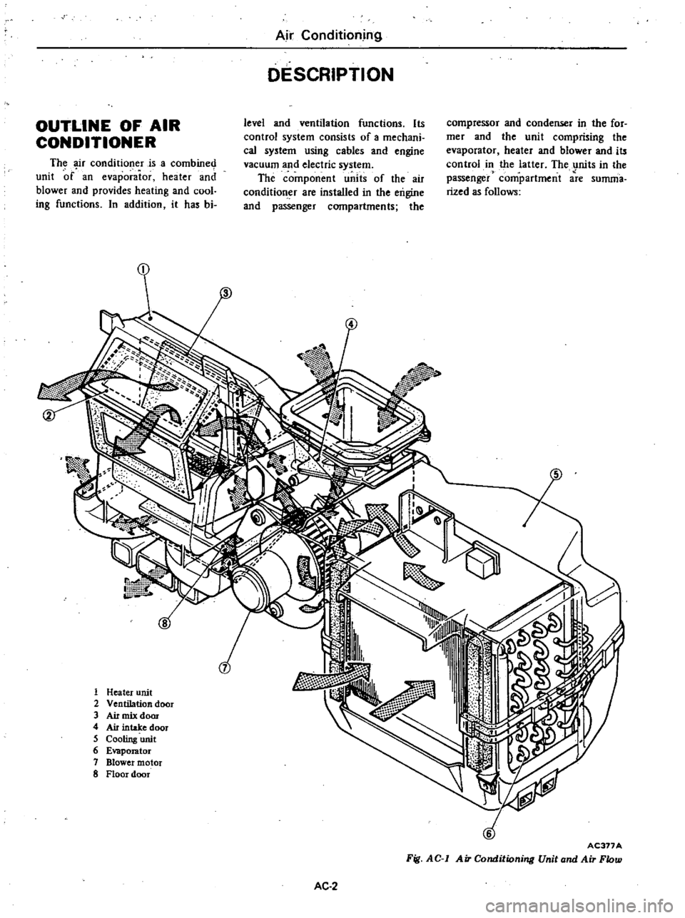
I
1
Heater
unit
2
Ventilation
door
3
Air
mix
dom
4
Air
intake
door
5
Cooling
unit
6
E
r
or
7
Blower
motor
8
Floor
door
AC377A
Fig
AC
1
Air
Conditioning
Unit
and
Air
Flow
AC
2
Page 504 of 548
REFRIGERATION
SYSTEM
If
you
were
to
paint
your
rmger
with
alcohol
your
finger
would
feel
cold
This
is
because
the
liquid
alcohol
takes
heat
away
from
your
rmger
while
it
evaporates
If
a
quickly
evapo
rating
liquid
such
as
alcohol
is
placed
in
a
container
inside
a
box
the
tern
Air
Conditioning
perature
inside
the
box
will
drop
This
is
because
the
alcohol
is
evaporated
absorbing
the
heat
from
the
air
inside
the
box
If
the
gaseous
alcohol
is
collected
and
cooled
with
cold
water
it
will
be
changed
back
into
a
liquid
by
absorption
of
its
heat
by
the
cold
water
The
cooler
operates
on
this
princi
1
r
I
Outside
air
U
Condenser
r
lf
P
9
n
U
Receiver
drier
AC378A
The
operation
of
the
five
devices
of
the
refrigeration
system
are
described
below
EVAPORATOR
The
heat
of
the
inside
air
which
is
force
irculated
by
the
blower
motor
is
absorbed
by
vaporizing
the
liquid
refrigerant
passed
through
the
evapora
tor
This
cools
the
air
l
t
High
pressure
gas
I
High
pressure
liquid
Compressor
Jj
COMPRESSOR
The
compressor
is
installed
to
the
side
of
the
engine
and
is
driven
by
crank
pulley
through
a
belt
The
refrig
erant
gas
leaving
the
evaporator
is
forced
out
to
the
condenser
by
com
pressor
and
the
low
pressure
refriger
ant
gas
is
compressed
to
a
high
pres
sure
and
high
temperature
AC3
pie
The
liquid
used
is
the
refrigerant
R
12
The
heat
inside
the
passenger
compartment
is
absorbed
by
changing
the
refrigerant
from
a
liquid
to
a
gas
and
then
dissipated
to
the
outside
by
changing
the
refrigerant
from
a
gas
back
to
a
liquid
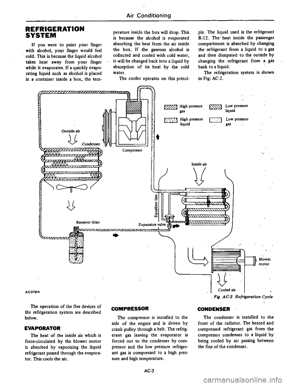
The
refrigeration
system
is
shown
in
Fig
AC
2
Low
pressure
liquid
C
J
Low
pressure
gas
Inside
air
v
n
Blower
1f
motor
Cooled
air
Fig
AC
2
Refrigeration
Cycle
CONDENSER
The
condenser
is
installed
to
the
front
of
the
radiator
The
heated
and
compressed
refrigerant
gas
from
the
compressor
condenses
to
a
liquid
by
being
cooled
by
air
passing
between
the
fins
of
the
condenser
Page 505 of 548
Air
Conditioning
RECEIVER
DRIER
The
receiver
drier
rves
the
pur
pose
of
storing
tl
e
liquid
refrigerant
The
amount
of
the
liquid
refrigerant
flowing
through
the
system
varies
with
the
operating
condition
of
the
air
conditioner
To
be
accurate
the
receiver
drier
stores
excess
amount
of
refrigerant
when
the
heat
load
is
low
ered
It
also
releases
stored
refrigerant
when
additional
cooling
is
needed
thus
maintaining
the
optimum
flow
of
refrigerant
within
the
system
The
receiver
drier
includes
a
strain
er
and
desiccant
They
have
the
job
of
removing
moisture
and
foreign
parti
cles
as
the
refrigerant
circulates
within
the
system
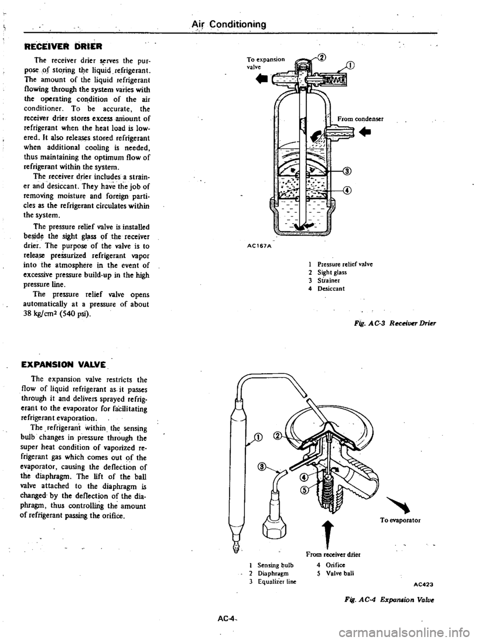
The
pressure
relief
valve
is
installed
beside
the
sight
glass
of
the
receiver
drier
The
purpose
of
the
valve
is
to
release
preSsurized
refrigerant
vapor
into
the
atmosphere
in
the
event
of
excessive
pressure
build
up
in
the
high
pressure
line
The
pressure
relief
valve
opens
automatically
at
a
pressure
of
about
38
kg
cm2
540
psi
EXPANSION
VALVE
The
expansion
valve
restricts
the
flow
of
liquid
refrigerant
as
it
passes
through
it
and
delivers
sprayed
refrig
erant
to
the
evaporator
for
faCilitating
refrigerant
evaporation
The
refrigerani
within
the
sensing
bulb
changes
in
pressure
through
the
super
heat
condit
ion
of
vaporized
re
frigerant
gas
which
comes
out
of
the
evaporator
causing
the
deflection
of
the
diaphragm
The
lift
of
the
ball
valve
attached
to
the
diaphragm
is
changed
by
the
deflection
of
the
dia
phragm
thus
controlling
the
amount
of
refrigerant
passing
the
orifice
AC
4
To
expansion
valve
rl
From
condenser
L
J
C
d
f
@
J
f
J
4
4
1
u
lc
AC167A
1
Pressure
relief
valve
2
Sight
glass
3
Suainer
4
Desiccant
Fig
AC
3
Receiver
Drier
JD
v
t
I
Sensing
bulb
2
Diaphragm
3
Eq
ualizer
line
From
receiver
drier
4
Orifice
5
Valve
ball
To
evaporator
Fig
A
C
4
Expansion
Valve
AC423
Page 506 of 548
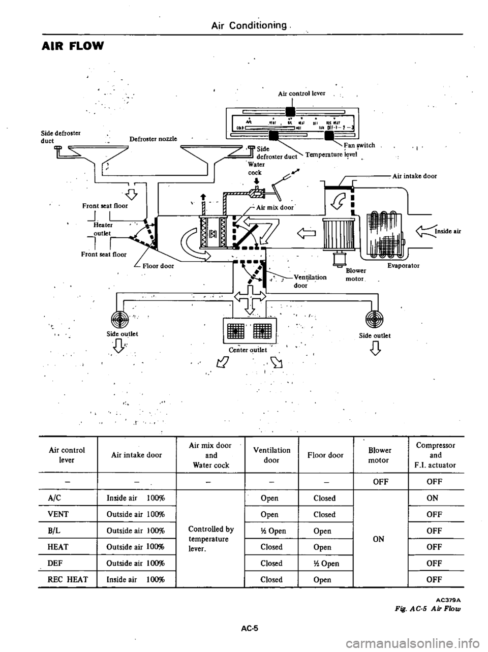
Air
Conditioning
AIR
FLOW
Air
control
lever
1M
l
r
I
1
all
IC
1T
I
tCliO
ar
afH
7
Sidedefrostcr
duct
Defroster
nozzle
L
Jf
SOd
Fan
switch
1
7
l
t
I
Air
intake
door
r
If
Ftont
seat
flOO
i
f
t
I
J
Heater
outlet
nside
air
l
Front
seat
floor
Evaporator
i
Side
outlet
D
I
I
IIll
91
i
Side
outlet
Center
udet
r2
D
I
Air
control
Air
mix
door
Ventilation
Blower
Compressor
Air
intake
door
and
Floor
door
and
lever
Water
cock
door
motor
F
1
actuator
OFF
OFF
AIC
Inside
air
100
Open
Closed
ON
VENT
Outside
air
100
Open
Closed
OFF
B
L
Outside
air
100
Controlled
by
0
Open
Open
OFF
temperature
ON
HEAT
Outside
air
100
lever
Closed
Open
OFF
DEF
Outside
air
100
Closed
0
Open
OFF
REC
HEAT
Inside
air
100
Closed
Open
OFF
AC379A
Fig
AC
S
Air
Flow
AC
5
Page 507 of 548
VACUUM
SYSTEM
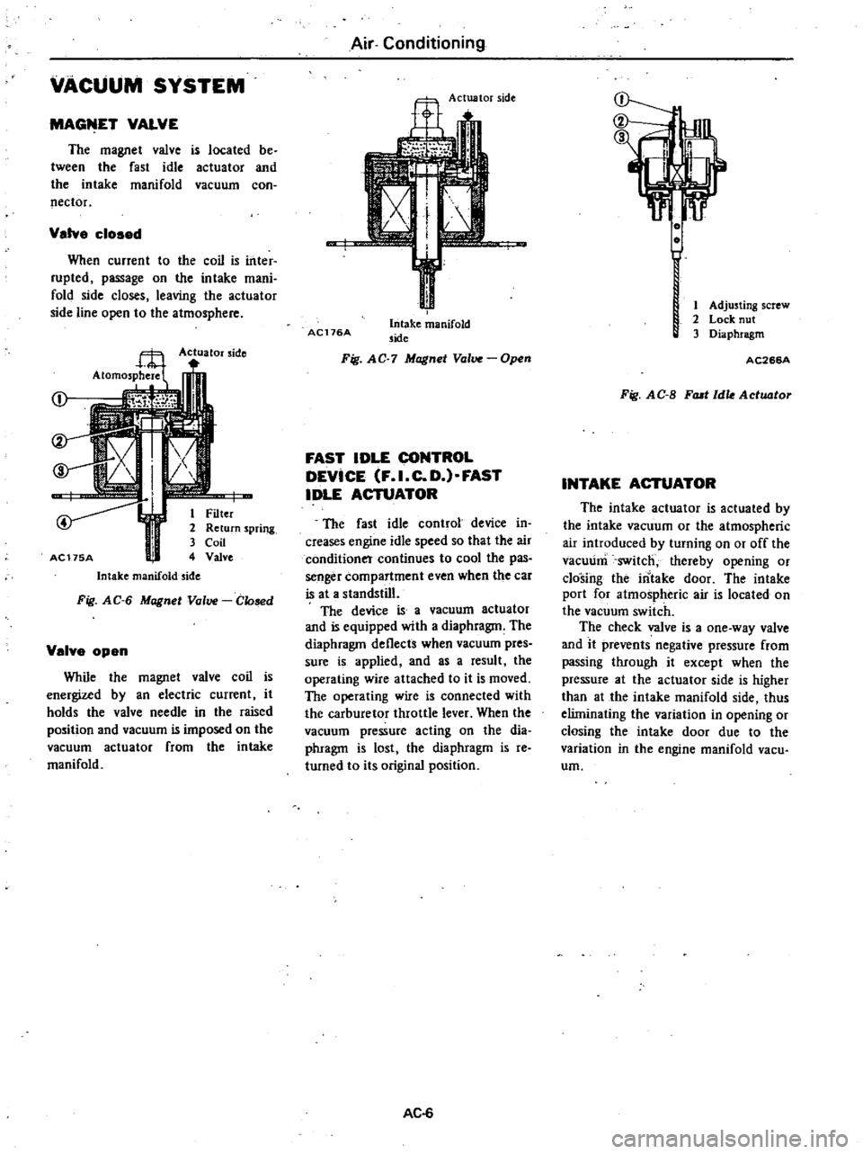
MAGfilET
VALVE
The
magnet
valve
is
located
be
tween
the
fast
idle
actuator
and
the
intake
manifold
vacuum
con
nector
Valve
cloaed
When
current
to
the
coil
is
inter
rupted
passage
on
the
intake
mani
fold
side
closes
leaving
the
actuator
side
line
open
to
the
atmosphere
Actuator
side
j
I
i
r
1
Filter
2
Return
spring
3
Coil
AC175A
4
Valve
Intake
manifold
side
Fig
AG
6
Magnet
Valve
Glosed
Velve
open
While
the
magnet
valve
coil
is
energized
by
an
electric
current
it
holds
the
valve
needle
in
the
raised
position
and
vacuum
is
imposed
on
the
vacuum
actuator
from
the
intake
manifold
Air
Conditioning
Actuator
side
AC176A
Intake
manifold
side
Fig
AG
7
Magnet
Valve
Open
FAST
IDLE
CONTROL
DEVICE
F
I
C
D
FAST
IDLE
ACTUATOR
The
fast
idle
control
device
in
creases
engine
idle
speed
so
that
the
air
conditioner
continues
to
cool
the
pas
senger
compartment
even
when
the
car
is
at
a
standstill
The
device
is
a
vacuum
actuator
and
is
equipped
with
a
diaphragm
The
diaphragm
deflects
when
vacuum
pres
sure
is
applied
and
as
a
result
the
operating
wire
attached
to
it
is
moved
The
operating
wire
is
connected
with
the
carburetor
throttle
lever
When
the
vacuum
pressure
acting
on
the
dia
phragm
is
lost
the
diaphragm
is
reo
turned
to
its
original
position
AC
6
1
Adjusting
screw
2
Lock
nut
3
Diaphragm
AC266A
Fig
AG
B
FlUI
Idle
Actuator
INTAKE
ACTUATOR
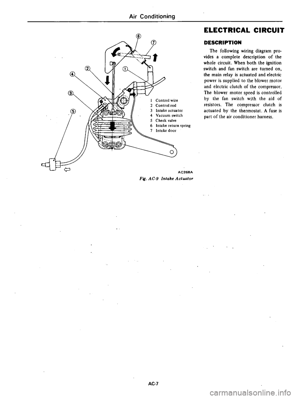
The
intake
actuator
is
actuated
by
the
intake
vacuum
or
the
atmospheric
air
introduced
by
turning
on
or
off
the
vacuum
switch
thereby
opening
or
closing
the
intake
door
The
intake
port
for
atmospheric
air
is
located
on
the
vacuum
switch
The
check
valve
is
a
one
way
valve
and
it
prevents
negative
pressure
from
passing
through
it
except
when
the
pressure
at
the
actuator
side
is
higher
than
at
the
intake
manifold
side
thus
eliminating
the
variation
in
opening
or
closing
the
intake
door
due
to
the
variation
in
the
engine
manifold
vacu
urn
Page 508 of 548
Air
Conditioning
4
1
Control
wire
2
Control
rod
3
Intake
actuator
4
Vacuum
switch
5
Check
valve
6
Intake
return
spring
7
Intake
door
AC268A
Fig
AC
9
Intake
Actuator
AC
7
ELECTRICAL
CIRCUIT
DESCRIPTION
The
following
wiring
diagram
pro
vides
a
complete
description
of
the
whole
circuit
When
both
the
ignition
switch
and
fan
switch
are
tu
ned
on
the
main
relay
is
actuated
and
electric
power
is
supplied
to
the
blower
motor
and
electric
clutch
of
the
compressor
The
blower
motor
speed
is
controlled
by
the
fan
switch
with
the
aid
of
resistors
The
compressor
clutch
is
actuated
by
the
thermostat
A
fuse
is
part
of
the
air
conditioner
harness
Page 509 of 548

Air
Conditioning
Ale
position
Main
relay
Blower
motor
Fan
switch
Fusible
r
link
o
c
Fuse
This
fuse
is
built
into
air
con
harnes
s
I
L
RW
B
5
d
2nd
I
I
olst
Resistor
1
Battery
Ignition
Fuse
1
switch
Micro
switch
Low
pressure
switch
0
Thermost
T
I
CompreSsor
clutch
roo
h
Magnet
valve
AC269A
VENT
8
L
HEAT
DEF
and
REC
HEAT
position
Main
relay
Blower
motor
Fusible
1
link
0
O
C
Fuse
This
fuse
is
built
into
air
coil
harness
RW
o
Fan
switch
Ignition
switch
r
o
Fuse
5
d
2nd
olsl
I
Resistor
0
1
Micro
switch
j
Battery
Low
pressure
switch
0
J
The
most
T
tr
r
I
Compressor
clutch
Magnet
valve
AC270A
Fig
AC
IO
Electrical
Circuit
Ac
a
Page 510 of 548
REFRIGERANT
R
12
The
refrigerant
used
in
the
air
conditioner
is
generally
called
Re
frigerant
12
R
12
No
other
refrig
erant
than
the
above
refrigerant
should
be
used
Note
Exercise
care
when
handling
re
frigerant
as
it
is
stored
under
high
pressure
COMPRESSOR
OIL
The
SUNISO
5GS
refrig
ration
lubricant
should
be
used
to
assure
the
successful
compressor
operation
Use
of
oils
other
than
recommended
or
mixing
of
the
oil
with
other
oils
would
cause
chemical
reaction
or
lead
to
lowered
viscosity
or
deficient
lubrica
tion
The
oil
absorbs
moisture
as
it
con
tacts
the
air
This
points
out
the
need
for
care
not
to
expose
it
to
atmos
phere
for
an
extended
period
of
time
MAINTENANCE
The
following
checks
and
main
tenance
are
especially
important
to
the
air
conditioner
I
Check
refrigerant
level
2
Check
refrigerant
leaks
3
Check
compressor
drive
belt
for
proper
deflection
4
Even
in
the
off
season
turn
the
compressor
for
10
minutes
at
least
once
a
month
by
running
the
engine
at
1
500
rpm
GENERAL
SERVICE
INSTRUCTIONS
If
dirt
water
or
air
enters
the
air
conditioner
system
it
will
be
seriously
affected
Be
sure
to
observe
the
following
I
Always
keep
the
working
place
clean
and
dry
and
free
from
dirt
and
Air
Conditioning
GENERAL
SERVICE
dust
Wipe
water
off
from
the
line
fittings
with
a
clean
cloth
before
dis
connecting
2
Have
all
necessary
tools
in
prepar
ation
beforehand
and
have
tools
clean
and
dry
3
Handling
plug
when
the
system
line
is
disconnected
4
Handling
compressor
oil
For
details
refer
to
each
descrip
tion
in
this
manual
SAFETY
PRECAUTIONS
WARNING
1
Since
direct
contact
of
the
liquid
refrigerant
with
your
skin
will
cause
frostbite
always
be
carelul
when
handling
the
refrigerant
Always
wear
goggles
to
protect
your
eyes
when
working
around
the
system
2
The
refrigerant
service
container
has
a
safe
strength
However
if
handled
incorrectly
it
will
ex
plode
Therelore
always
follow
the
instructions
On
the
label
In
particular
never
store
it
in
a
hot
location
above
520e
1260F
or
drop
it
from
a
high
height
3
The
refrigerant
gas
is
odorless
and
colorless
and
breathing
may
become
difficult
due
to
the
lack
of
oxygen
Since
the
relrigerant
gas
is
heavier
than
air
and
will
lay
close
to
the
floor
be
espe
cially
careful
when
handling
it
in
small
confined
spaces
4
The
refrigerant
itself
is
nonflam
mable
However
a
toxic
gas
phosgene
gas
is
produced
when
it
contacu
fire
and
special
care
is
therefore
required
when
check
ing
for
leaks
in
the
system
with
a
halide
torch
5
Do
not
steam
clean
On
the
sys
tem
especially
condenser
since
excessively
high
pressure
will
build
up
in
the
system
resulting
in
explosion
of
the
system
The
above
precautions
are
essen
tial
in
handling
of
Refrigerant
12
and
their
strict
observation
AC
9
requires
sufficient
training
Therefore
it
is
of
first
impor
tance
that
any
other
personnel
than
a
well
trained
serviceman
should
not
be
allowed
to
handle
the
refrigerant
EVACUATING
AND
CHARGING
SYSTEM
During
servicing
use
caution
to
keep
air
from
getting
into
refrigerant
When
air
enters
the
system
all
refriger
ant
must
be
evacuated
from
system
prior
to
charging
new
refrigerant
Air
in
refrigerant
has
the
following
delete
rious
effects
1
Since
the
condensation
tempera
ture
of
the
air
is
extremely
low
the
air
will
not
be
condensed
when
refrigerant
gas
is
condensed
in
the
condenser
and
the
air
will
thus
remain
in
gaseous
fonn
Consequently
the
effective
thermal
transmission
area
of
condenser
for
refrigerant
gas
will
be
reduced
and
refrigerant
gas
to
be
condensed
will
be
reduced
The
pressure
rise
will
become
proportional
to
the
volume
of
the
air
in
system
2
When
air
and
refrigerant
are
r
tixed
in
system
a
chemical
reaction
will
be
produced
and
hydrochloric
acid
which
will
adversely
affect
the
aluminum
copper
iron
and
other
materials
in
system
may
be
generated
HANDLING
MANIFOLD
GAUGE
The
pressure
at
the
high
and
low
sides
of
system
should
be
measured
when
evacuating
and
charging
refrig
erant
and
when
diagnosing
trouble
in
the
system
The
manifold
gauge
is
used
for
these
purposes
A
manifold
gauge
has
two
pressure
gauges
a
low
pressure
gauge
and
a
high
pressure
gauge
These
gauges
are
connected
to
the
high
and
low
side
service
valves
of
system
through
flexible
charging
hoses
The
construction
of
manifold
gauge
is