DATSUN 210 1979 Workshop Manual
Manufacturer: DATSUN, Model Year: 1979, Model line: 210, Model: DATSUN 210 1979Pages: 548, PDF Size: 28.66 MB
Page 51 of 548
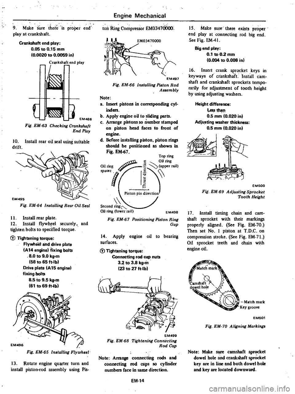
9
Make
SUre
there
is
proper
end
play
at
crankshaft
Crankshaft
end
play
0
05toO
15mm
0
OO20
to
0
0059
in
laJlk
h
end
play
J
EM486
Fig
EM
63
Checking
Crank
luJft
End
Play
10
Install
rear
oil
seal
using
suitable
drift
Fig
EM
64
n
talling
Rear
Oil
Seal
II
Install
rear
plate
12
Install
flywh
el
secwely
and
tighten
bolts
to
specified
torque
dl
Tightening
torque
Flywheel
and
drive
plate
A
14
engine
fixing
bolts
8
0
to
9
0
kg
m
58
to
65
ft
Ib
Drive
plate
A
15
engine
fixing
bolts
8
5
to
9
5
kg
m
61
to
69
ft
b
Fig
EM
65
n
talling
Flywheel
13
Rotate
engine
quarter
turn
and
install
piston
rod
assembly
using
Pis
Engine
Mechanical
ton
Ring
Compressor
EM03470000
EM497
Fig
EM
66
tolling
Platon
Rod
Assem
bly
Note
a
Insert
pistons
in
L
r
nding
cyl
inders
b
Apply
engine
oil
to
sliding
parts
c
Arrange
pistons
so
number
stamped
on
piston
head
faces
to
front
of
engine
d
Before
installing
piston
piston
rings
should
be
positioned
as
shown
in
Fig
EM
67
Second
ring
Oil
ring
lower
rail
EM49B
Fig
EM
67
Positioning
Piston
Ring
Gap
14
Apply
engine
oil
to
bearing
surfaces
dl
Tighte
ning
torque
Connecting
rod
cap
nuts
3
2
to
3
8
kg
m
23
to
27
ft
b
EM499
Fig
EM
68
Tightening
Connecting
Rod
Cap
Note
Am11
connecting
rods
and
connecting
rod
caps
so
cylinder
numben
face
in
same
direction
EM
14
I
S
Make
sure
there
exists
proper
end
play
at
connecting
rod
big
end
See
Fig
EM41
Big
end
play
0
1
to
0
2
mm
0
004
to
0
008
in
16
Insert
crank
sprocket
keys
in
keyways
of
crankshaft
Install
cam
shaft
and
crankshaft
sprockets
tempo
rarily
for
adjustment
of
tooth
height
by
using
adjusting
washers
Height
dif
Less1
h
l11
0
5
mm
0
020
in
Adjusting
washer
thickness
0
5
mm
10
020
in
EM500
Fig
EM
69
Adju
ting
Sprocket
Tooth
Height
17
Install
tinting
chain
and
cam
shaft
sprocket
with
their
markings
properly
aligned
See
Fig
EM
70
Then
set
No
I
piston
at
T
D
C
on
compression
stroke
See
Fig
EM
71
Oil
sprocket
teeth
and
chain
with
engine
oil
Match
mark
Key
groove
EM501
Fig
EM
70
Aligning
Markinga
Note
Make
sure
camshaft
sprocket
dowel
hole
and
crankshaft
sprocket
key
are
in
line
and
both
dowel
hole
and
key
are
located
downward
Page 52 of 548
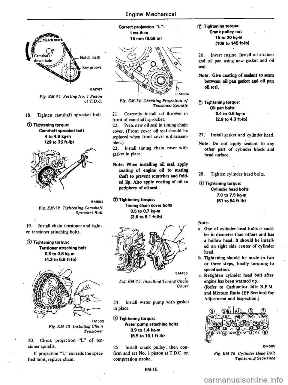
m
k
camSM9tJ
down
hole
Key
groove
EM767
Fig
EM
11
Setting
No
I
Piston
atT
D
C
18
Tighten
camshaft
sprocket
bolt
ifl
Tightening
torque
Camshaft
sprocket
bolt
4
to
4
8
kg
m
29
to
35
fHbl
EM502
Fig
EM
72
Tightening
Camshaft
Sprocket
Bolt
19
Install
chain
tensioner
and
tight
en
tensioner
attaching
bolts
ifl
Tightening
torque
Tensioner
enaching
bolt
0
6
to
0
8
kg
m
14
3
to
5
8
ft
b
EM503
Fig
EM
73
Installing
Chain
Tensioner
20
Check
projection
L
of
ten
sioner
spindle
If
projection
L
exceeds
the
speci
fied
limit
replace
chain
Engine
Mechanical
Correct
projection
L
Less
than
15
mm
0
59
inl
lEM504
Fig
EM
74
Checking
Projection
of
Tf
nsioner
Spindle
21
Correctly
install
oil
thrower
in
front
of
camshaft
sprocket
22
Press
new
oil
seal
in
timing
chain
cover
F
ran
t
cover
oil
seal
should
be
replaced
when
front
cover
is
disassem
bled
23
Install
timing
chain
cover
with
gasket
in
place
Note
When
inatalling
oil
seal
apply
coating
of
engine
oil
to
mating
shaft
to
prevent
scratches
and
fold
ed
lip
Also
apply
coating
of
oil
to
periphery
of
oil
seal
ifl
Tightening
torque
Timing
chain
cover
bolts
0
5
to
0
7
kg
m
3
6
to
5
1
ft
Ib
Z5
1
o
j
I
t
f
4
EM455
Fig
EM
75
Installing
Timing
Chain
Covtr
24
Install
water
pump
with
gasket
in
place
ifl
Tightening
torque
Water
pump
attaching
bolts
0
9
to
1
4
kg
m
16
5
to
10
1
ft
bl
25
Install
crank
pulley
then
con
firm
and
set
No
I
piston
at
T
D
C
on
compression
stroke
EM
15
ifl
Tightening
torque
Crank
pulley
nut
15to
20
kg
m
108
to
145
ft
b
26
Invert
engine
Install
oil
stniiner
and
oil
pan
using
new
gasket
and
oil
seal
Note
Give
coating
of
sealant
to
seam
between
oil
pan
gasket
and
oil
pan
oil
seal
ifl
Tightening
torque
Oil
pan
bolts
0
4
to
0
6
kg
m
12
9
to
4
3
ft
lb
27
Install
gasket
and
cylinder
head
Note
Do
not
apply
sealant
to
any
other
part
of
cylinder
block
and
head
surface
28
Tighten
cylinder
head
bolts
ifl
Tightening
torque
Cylinder
head
bolts
7
0
to
7
5
kg
m
51
to
54
ft
IM
Note
a
One
of
cylinder
head
bolts
is
smal
ler
in
diameter
than
others
and
has
a
hollow
head
It
should
be
install
ed
on
right
side
center
of
cylinder
head
b
Tightening
should
be
made
in
two
or
three
steps
finally
torquing
to
specification
c
Retighten
cylinder
head
bolt
after
engine
has
been
warmed
up
Refer
to
Carburetor
Idle
R
P
M
and
Mixture
Ratio
EF
Section
for
Adjustment
and
Inspection
EM505
Fig
EM
76
Cylinder
Head
Bolt
Tightening
Sequence
Page 53 of 548
29
Apply
engine
oiho
both
ends
of
push
rods
and
insert
in
proper
se
quence
30
Apply
engine
oil
to
valve
stem
end
and
rocker
arm
contact
surfaces
Position
rocker
shaft
assembly
on
cyI
inder
head
31
Tighten
rocker
shaft
bracket
bolts
to
specified
torque
fJ
Tightening
torque
Rocker
shaft
bracket
bolts
2
0
to
2
5
kg
m
14
to
18
ft
b
Note
Tightening
should
be
done
in
two
or
three
stages
outwardly
from
center
bracket
EM506
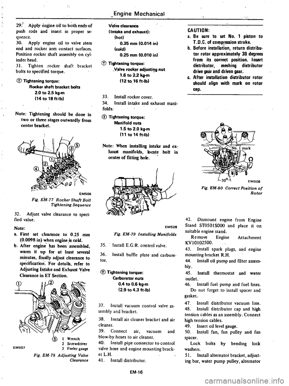
Fig
EM
77
Rocker
Shaft
Bolt
Tightening
Sequence
32
Adjust
valve
clearance
to
speci
fied
value
Note
a
First
set
clearance
to
0
25
mm
0
0098
in
when
engine
iscold
b
After
engine
has
been
assembled
warm
it
up
for
at
least
several
minutes
finally
adjust
clearance
to
specification
For
details
refer
to
Adjusting
Intake
and
Exhaust
Valve
Clearance
in
ET
Section
EM507
or
Wrench
2
Screwdriver
3
Feeler
gauge
Fig
EM
78
Adjusting
Value
Clearance
Engine
Mechanical
Valve
clearance
Intake
and
exhaust
hot
0
35
mm
0
014
in
cold
0
25
mm
0
010
in
fJ
Tightening
torque
Velve
rocker
adjusti
g
nut
1
6
to
2
2
kltm
12
to
16
ft
b
33
Install
rocker
cover
34
Install
intake
and
exhaust
mani
folds
fJ
Tightening
torque
Manifold
nuts
1
5
to
2
0
kg
m
11
to
14
fHb
Note
When
installing
intake
and
ex
haust
manifolds
locate
bolt
in
center
of
fitting
hole
EM528
Fig
EM
79
Installing
Manifolds
35
Install
E
G
R
control
valve
36
Install
baffle
plate
and
carbure
tor
fJ
Tightening
torque
Carburetor
nuts
0
4
to
0
6
kg
m
2
9
to
4
3
ft
Ibl
37
Install
vacuum
control
valve
as
sembly
and
bracket
38
Install
air
cleaner
bracket
and
air
cleaner
39
Connect
air
vacuum
and
blow
by
hoses
to
air
cleaner
40
Install
pipe
connector
to
control
valve
hose
and
engine
mounting
brack
etLR
41
Install
distributor
EM
16
CAUTION
a
8e
sure
to
set
No
1
piston
to
LD
C
of
compression
stroke
b
Before
instaliation
return
distribu
tor
rotor
approximately
30
degrees
from
its
correct
position
Insert
distributor
meshing
distributor
drive
gear
and
driven
gear
c
After
installation
distributor
rotor
should
align
with
mark
on
rotor
cap
J
No
1
mark
EM508
Fig
EM
80
Cornct
P05ition
of
Rotor
42
Dismount
engine
from
Engine
Stand
ST0501S000
and
place
it
on
suitable
engine
stand
Re
move
Engine
Attachment
KVlOI
2500
43
Install
spark
plugs
and
engine
mounting
bracket
R
H
44
Install
oil
pump
and
ftIter
assem
bly
45
Install
thermostat
and
water
outlet
46
Install
fuel
pump
and
fuel
lines
Do
not
forget
to
install
spacer
and
gasket
47
Install
distributor
vacuum
line
48
Install
distributor
cap
and
high
tension
cables
as
an
assembly
Connect
high
tension
cables
49
Insert
oil
level
gauge
50
Install
fan
fan
pulley
and
fan
spacer
Lock
bolt
by
bending
lock
washers
51
Install
alternator
bracket
adjust
ing
bar
water
pump
pulley
alternator
Page 54 of 548
and
fan
belt
Be
sure
that
belt
deflection
is
held
within
specified
range
when
moderate
force
is
applied
midway
between
pul
leys
Belt
deflection
8t012mm
0
31
to
0
47
in
Force
10
kg
22Ib
Deflection
Fan
pulley
f
Crank
pulley
Alternator
pulley
EM768
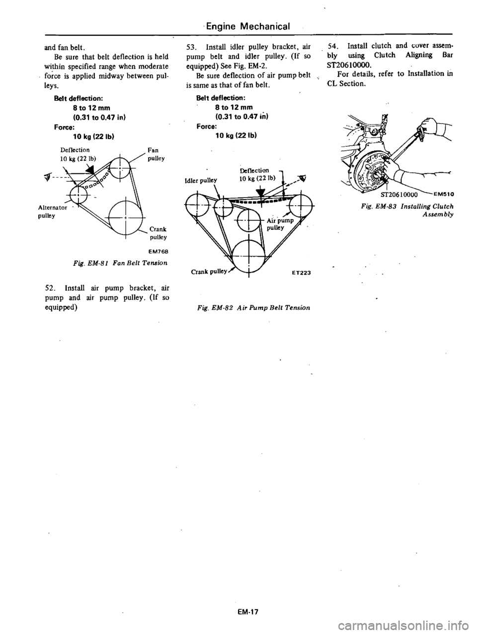
Fig
EM
81
Fan
Belt
Temion
52
Install
air
pump
bracket
air
pump
and
air
pump
pulley
If
so
equipped
Engine
Mechanical
53
Install
idler
pulley
bracket
air
pump
belt
and
idler
pulley
If
so
equipped
See
Fig
EM
2
Be
sure
deflection
of
air
pump
belt
is
same
as
that
of
fan
belt
Belt
deflection
8
to
12
mm
0
31
to
0
47
in
Force
10
kg
22Ib
Deflection
10
kg
22Ib
Fig
EM
82
Air
Pump
Belt
Tension
EM
17
54
Install
clutch
and
cover
assem
bly
using
Clutch
Aligning
Bar
STI0610000
For
details
refer
to
Installation
in
CL
Section
Fig
EM
83
Installing
Clutch
Assembly
Page 55 of 548
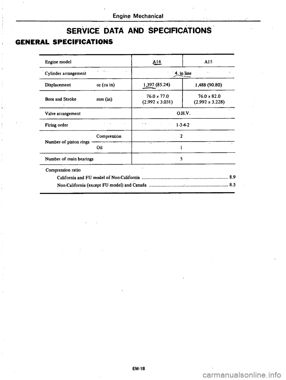
Engin
Mechanical
SERVICE
DATA
AND
8PECIRCATION8
GENERAL
SPECIFICATIONS
Engine
model
AI5
Cylinder
arrangement
4
in
line
Displacement
cc
cu
in
1
397
85
24
I
488
90
80
Bore
and
Stroke
mm
in
76
0
x
77
0
76
0
x
82
0
2
992
x
3
031
2
992
x
3
228
Valve
arrangement
OR
V
Firing
order
I
3
4
2
Compression
2
Number
of
piston
rings
Oil
Number
of
main
bearings
5
Compression
ratio
California
and
FU
model
of
Non
California
Non
California
except
FU
model
and
Canada
EM
18
8
9
8
5
Page 56 of 548
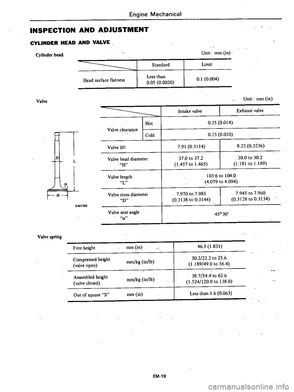
Engine
Mechanical
INSPECTION
AND
ADJUSTMENT
CYLINDER
HEAD
AND
VALVE
Cylinder
head
Unit
mm
in
Standard
Limit
Head
surface
flatness
Less
than
0
05
0
0020
0
1
0
004
Valve
Unit
mm
in
j
I
Hot
Valve
clearance
I
Cold
Intake
valve
Exhaust
valve
0
35
0
014
0
25
0
010
Valve
lift
7
91
0
3114
8
22
0
3236
H
37
0
to
37
2
1
457
to
1
465
30
0
to
30
2
1
181
to
1
189
D
L
Valve
head
diameter
a
H
Valve
length
L
103
6
to
104
0
4
079
to
4
094
D
7
970
to
7
985
0
3138
to
0
3144
7
945
to
7
960
0
3128
to
0
3134
Valve
stem
diameter
EM769
Valve
seat
angle
a
45030
Valve
spring
Free
height
mm
in
46
5
1
831
Compressed
height
mm
kg
in
lb
30
2
22
2
to
25
6
valve
open
1
189
49
0
to
56
4
Assembled
height
mm
kg
in
lh
38
7
544
to
62
6
valve
closed
1
524
120
0
to
138
0
Out
of
square
S
mm
in
Less
than
1
6
0
063
EM
19
Page 57 of 548
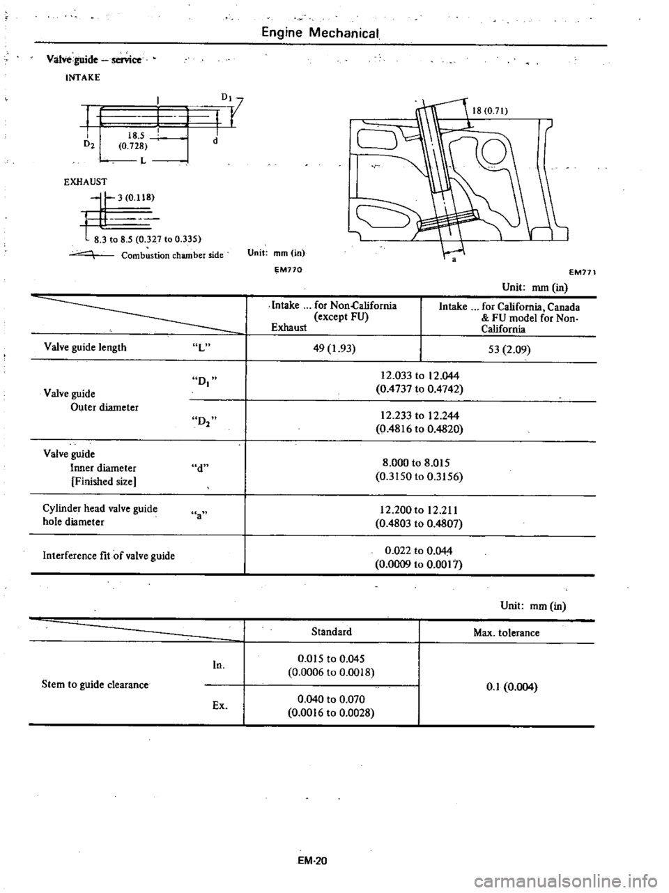
Valve
guide
senice
INTAKE
f
D21
Dl
I
r
I
I
I
d
18
5
0
728
L
EXHAUST
II
3
0
118
t
81
o
8
5
327
to
0
335
Combustion
chamber
ide
Valve
guide
length
L
D
Valve
guide
Outer
diameter
D2
Valve
guide
Inner
diameter
Finished
size
d
Cylinder
head
valve
guide
hole
diameter
a
Interference
fit
of
valve
guide
In
Stem
to
guide
clearance
Ex
Engine
Mechanical
1
Unit
mm
in
EM770
Intake
for
Non
California
except
FU
Exhaust
49
1
93
EM171
Unit
mm
in
Intake
for
California
Canada
FU
model
for
Non
California
53
2
09
12
0331012
044
0
4737
to
0
4742
12
233
to
12
244
0
4816
to
0
4820
8
000
to
8
015
0
3150
to
0
3156
12
200
to
12
211
0
4803
to
0
4807
0
022
to
0
044
0
0009
to
0
0017
Standard
0
Q15
to
0
045
0
0006
to
0
0018
0
040
to
0
070
0
0016
to
0
0028
EM
20
Unit
mm
in
Max
tolerance
0
1
0
004
Page 58 of 548
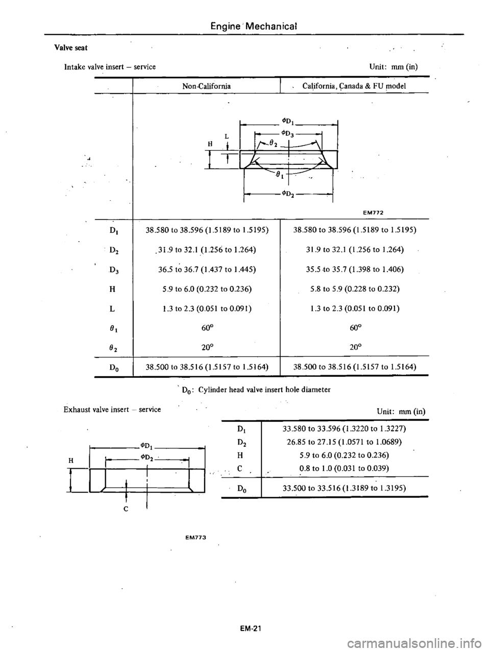
Engine
Mechanical
Valve
seat
Intake
valve
insert
service
Non
California
Unit
mm
in
California
9anada
FU
model
H
L
I
I
D
D
1
02
1
1
1
J
Ol
I
I
D
38
580
to
38
596
1
5189
to
1
5195
D2
31
9
to
32
1
1
256
to
1
264
D3
36
5
to
36
7
I
437
to
I
445
H
5
9
to
6
0
0
232
to
0
236
L
1
3
to
2
3
0
051
to
0
091
0
600
O2
200
Do
38
500
to
38
516
1
5157
to
1
5164
D2
EM772
38
580
to
38
596
1
5189
to
1
5195
31
9
to
32
1
1
256
to
1
264
35
5
to
35
7
1
398
to
I
406
5
8
to
5
9
0
228
to
0
232
1
3
to
2
3
0
051
to
0
091
600
200
38
500
to
38
516
1
5157
to
1
5164
Do
Cylinder
head
valve
insert
hole
diameter
Exhaust
valve
insert
service
D
D
D2
I
D2
I
I
H
H
I
I
l
I
C
Do
C
EM773
EM
21
Unit
mm
in
33
580
to
33
596
1
3220
to
1
3227
26
85
to
27
15
1
0571
to
1
0689
5
9
to
6
0
0
232
to
0
236
0
8
to
1
0
0
031
to
0
039
33
500
to
33
516
1
3189
to
1
3195
Page 59 of 548
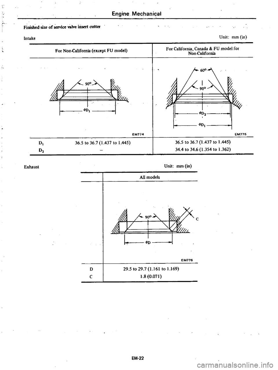
Engine
Mechanical
Finished
size
of
service
valve
insert
cutter
Intake
Exhaust
Unit
mm
in
For
Non
Clilifornia
except
FU
model
For
California
Canada
FU
model
for
Non
California
T
fil
@
Lr
I
I
JII
I
I
I
I
I
I
Dl
I
D
EM774
EM775
D
D2
36
5
to
36
7
1437
to
I
445
36
5
to
36
7
1
437
to
1
445
34
4
to
34
6
1
354
to
1
362
Unit
mm
in
All
models
j
III
900
C
WII
L
I
I
EM776
D
C
29
5
to
29
7
1
161
to
1
169
1
8
0
071
EM
22
Page 60 of 548
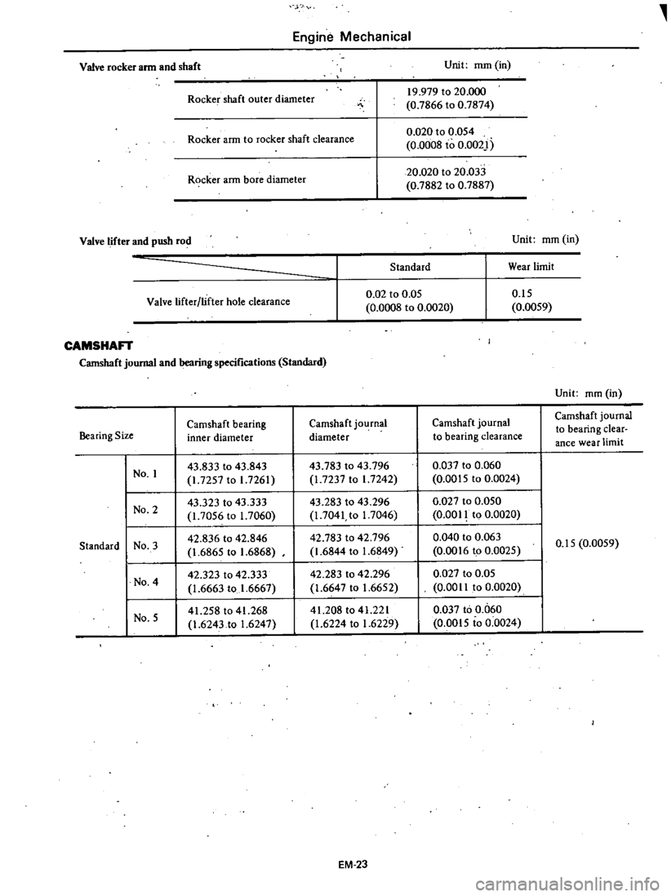
Engine
Mechanical
Valve
rocker
arm
and
shaft
Unit
mm
in
Rocke
shaft
outer
diameter
19
979
to
20
000
0
7866
to
0
7874
Rocker
arm
to
rocker
shaft
clearance
0
020
to
0
054
0
0008
to
0
002
Rocker
ann
bore
diameter
20
020
to
20
033
0
7882
to
0
7887
Valve
lifter
and
push
rod
Unit
mm
in
Standard
Wear
limit
Valve
lifter
lifter
hole
clearance
0
02
to
0
05
0
0008
to
0
0020
0
15
0
0059
CAMSHAn
Camshaft
journal
and
bearing
specifications
Standard
Camshaft
bearing
Camshaft
journal
Camshaft
journal
Bearing
Size
inner
diameter
diameter
to
bearing
clearance
No
I
43
833
to
43
843
43
783
to
43
796
0
037
to
0
060
I
7257
to
I
7261
1
7237
to
I
7242
0
0015
to
0
0024
No
2
43
323
to
43
333
43
283
to
43
296
0
027
to
0
050
1
7056
to
1
7060
I
7041
to
I
7046
0
0011
to
0
0020
Standard
No
3
42
836
to
42
846
42
783
to
42
796
0
040
to
0
063
1
6865
to
1
6868
1
6844
to
1
6849
0
0016
to
0
0025
No
4
42
323
to
42
333
42
283
to
42
296
0
027
to
0
05
1
6663
to
1
6667
1
6647
to
1
6652
0
00
II
to
0
0020
No
5
41
258
to
41
268
41
208
to
41
221
0
037
to
0
060
1
6243
to
1
6247
1
6224
to
1
6229
0
0015
to
0
0024
EM
23
Unit
mm
in
Camshaft
journal
to
bearing
clear
ance
wear
limit
0
15
0
0059