DODGE NEON 1999 Service Repair Manual
Manufacturer: DODGE, Model Year: 1999, Model line: NEON, Model: DODGE NEON 1999Pages: 1200, PDF Size: 35.29 MB
Page 801 of 1200
OIL PUMP
REMOVAL
(1) Disconnect negative cable from battery.
(2) Remove Timing Belt. Refer to procedure in this
section.
(3) Remove Oil Pan. Refer to procedure in this sec-
tion.
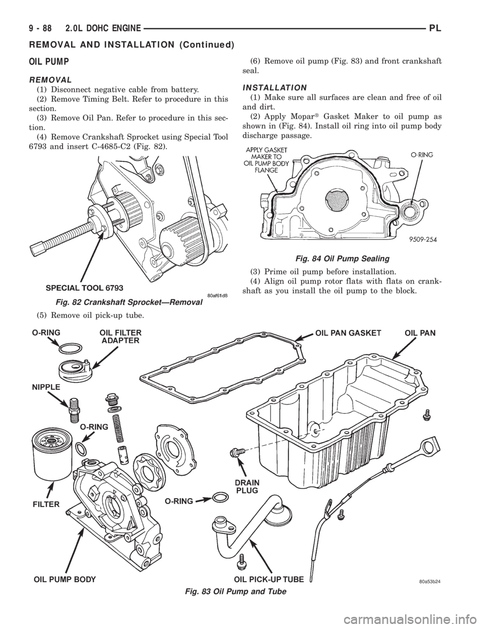
(4) Remove Crankshaft Sprocket using Special Tool
6793 and insert C-4685-C2 (Fig. 82).
(5) Remove oil pick-up tube.(6) Remove oil pump (Fig. 83) and front crankshaft
seal.INSTALLATION
(1) Make sure all surfaces are clean and free of oil
and dirt.
(2) Apply MopartGasket Maker to oil pump as
shown in (Fig. 84). Install oil ring into oil pump body
discharge passage.
(3) Prime oil pump before installation.
(4) Align oil pump rotor flats with flats on crank-
shaft as you install the oil pump to the block.
Fig. 83 Oil Pump and Tube
Fig. 82 Crankshaft SprocketÐRemoval
Fig. 84 Oil Pump Sealing
9 - 88 2.0L DOHC ENGINEPL
REMOVAL AND INSTALLATION (Continued)
Page 802 of 1200
NOTE: Front crankshaft seal MUST be out of pump
to align, or damage may result.
(5) Torque all oil pump attaching bolts to 28 N´m
(250 in. lbs.)
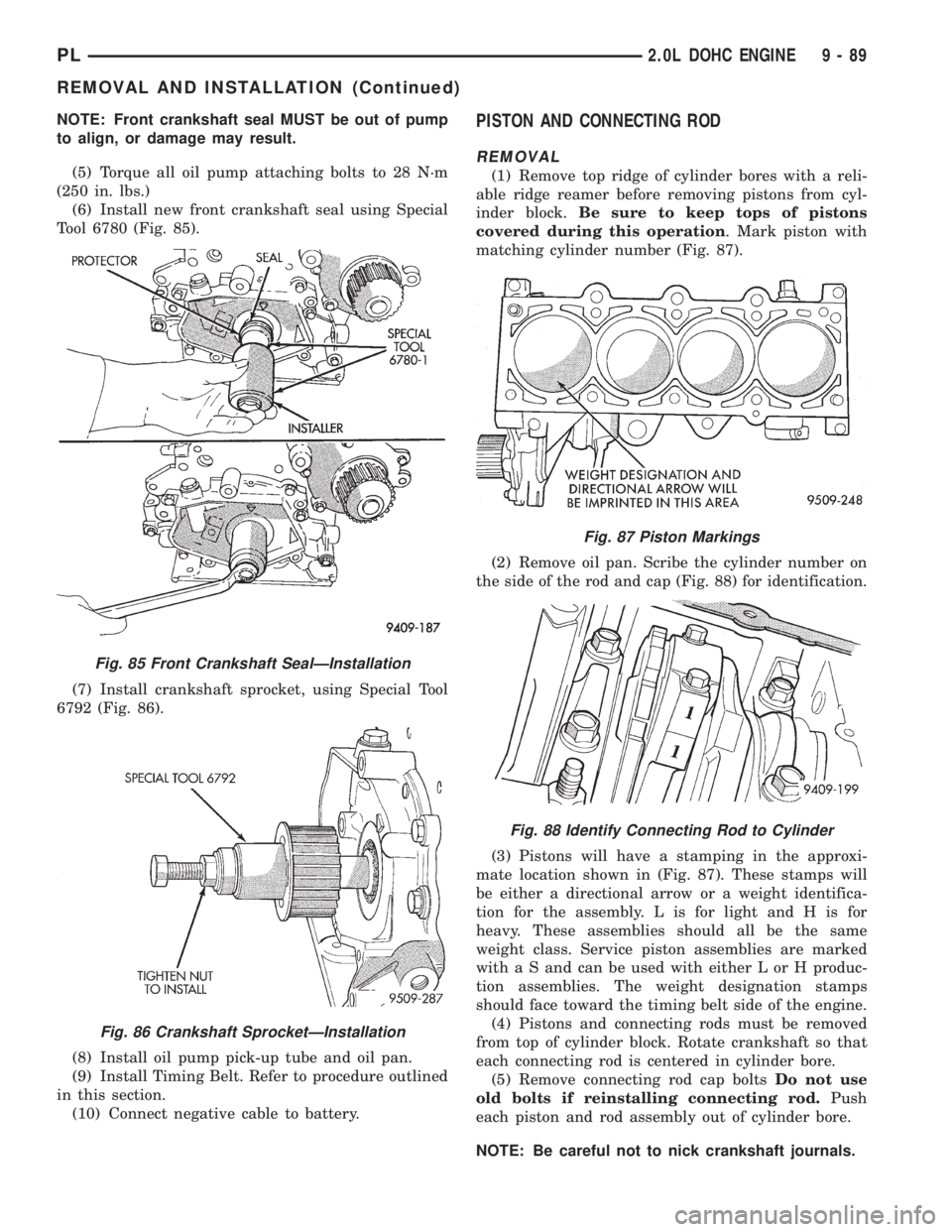
(6) Install new front crankshaft seal using Special
Tool 6780 (Fig. 85).
(7) Install crankshaft sprocket, using Special Tool
6792 (Fig. 86).
(8) Install oil pump pick-up tube and oil pan.
(9) Install Timing Belt. Refer to procedure outlined
in this section.
(10) Connect negative cable to battery.PISTON AND CONNECTING ROD
REMOVAL
(1) Remove top ridge of cylinder bores with a reli-
able ridge reamer before removing pistons from cyl-
inder block.Be sure to keep tops of pistons
covered during this operation. Mark piston with
matching cylinder number (Fig. 87).
(2) Remove oil pan. Scribe the cylinder number on
the side of the rod and cap (Fig. 88) for identification.
(3) Pistons will have a stamping in the approxi-
mate location shown in (Fig. 87). These stamps will
be either a directional arrow or a weight identifica-
tion for the assembly. L is for light and H is for
heavy. These assemblies should all be the same
weight class. Service piston assemblies are marked
with a S and can be used with either L or H produc-
tion assemblies. The weight designation stamps
should face toward the timing belt side of the engine.
(4) Pistons and connecting rods must be removed
from top of cylinder block. Rotate crankshaft so that
each connecting rod is centered in cylinder bore.
(5) Remove connecting rod cap boltsDo not use
old bolts if reinstalling connecting rod.Push
each piston and rod assembly out of cylinder bore.
NOTE: Be careful not to nick crankshaft journals.
Fig. 85 Front Crankshaft SealÐInstallation
Fig. 86 Crankshaft SprocketÐInstallation
Fig. 87 Piston Markings
Fig. 88 Identify Connecting Rod to Cylinder
PL2.0L DOHC ENGINE 9 - 89
REMOVAL AND INSTALLATION (Continued)
Page 803 of 1200
(6) After removal, install bearing cap on the mat-
ing rod.
(7) Piston and Rods are serviced as an assembly.
PISTON RINGÐREMOVAL
(1) ID mark on face of upper and intermediate pis-
ton rings must point toward piston crown.
(2) Using a suitable ring expander, remove upper
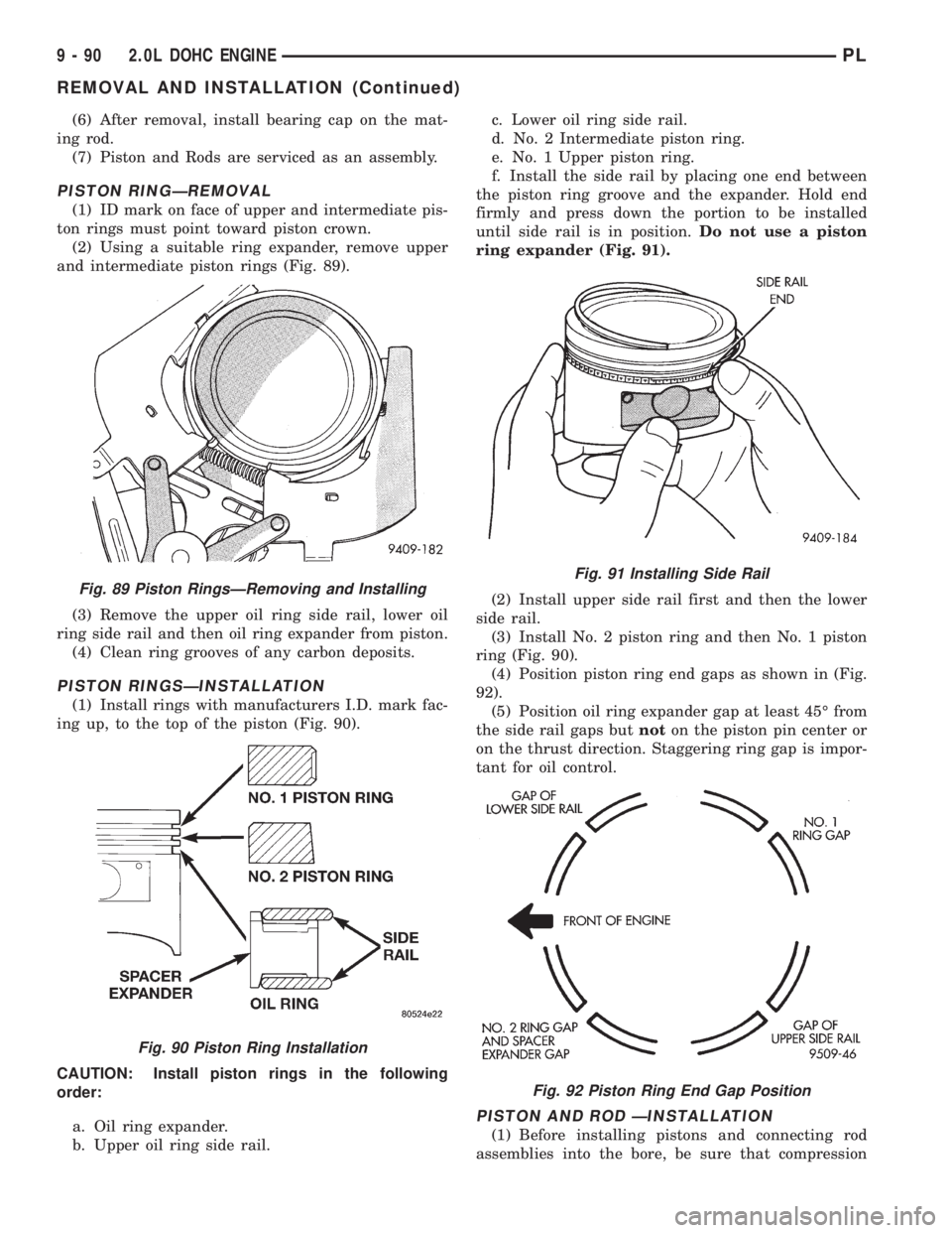
and intermediate piston rings (Fig. 89).
(3) Remove the upper oil ring side rail, lower oil
ring side rail and then oil ring expander from piston.
(4) Clean ring grooves of any carbon deposits.
PISTON RINGSÐINSTALLATION
(1) Install rings with manufacturers I.D. mark fac-
ing up, to the top of the piston (Fig. 90).
CAUTION: Install piston rings in the following
order:
a. Oil ring expander.
b. Upper oil ring side rail.c. Lower oil ring side rail.
d. No. 2 Intermediate piston ring.
e. No. 1 Upper piston ring.
f. Install the side rail by placing one end between
the piston ring groove and the expander. Hold end
firmly and press down the portion to be installed
until side rail is in position.Do not use a piston
ring expander (Fig. 91).
(2) Install upper side rail first and then the lower
side rail.
(3) Install No. 2 piston ring and then No. 1 piston
ring (Fig. 90).
(4) Position piston ring end gaps as shown in (Fig.
92).
(5) Position oil ring expander gap at least 45É from
the side rail gaps butnoton the piston pin center or
on the thrust direction. Staggering ring gap is impor-
tant for oil control.
PISTON AND ROD ÐINSTALLATION
(1) Before installing pistons and connecting rod
assemblies into the bore, be sure that compression
Fig. 89 Piston RingsÐRemoving and Installing
Fig. 90 Piston Ring Installation
Fig. 91 Installing Side Rail
Fig. 92 Piston Ring End Gap Position
9 - 90 2.0L DOHC ENGINEPL
REMOVAL AND INSTALLATION (Continued)
Page 804 of 1200
ring gaps are staggered so that neither is in line with
oil ring rail gap.
(2) Before installing the ring compressor, make
sure the oil ring expander ends are butted and the
rail gaps located as shown in (Fig. 92).
(3) Immerse the piston head and rings in clean
engine oil, slide the ring compressor, over the piston
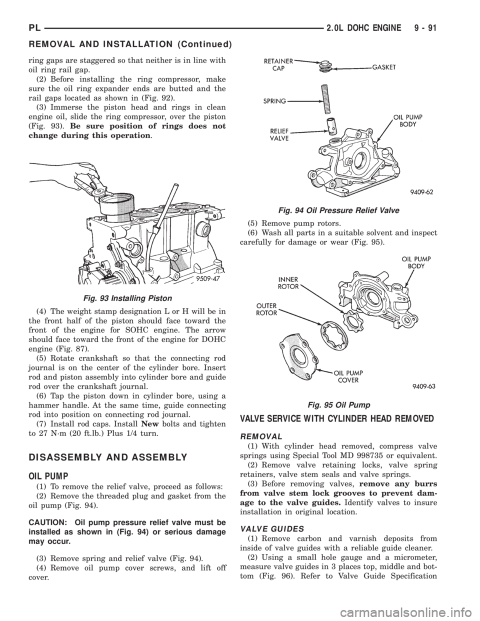
(Fig. 93).Be sure position of rings does not
change during this operation.
(4) The weight stamp designation L or H will be in
the front half of the piston should face toward the
front of the engine for SOHC engine. The arrow
should face toward the front of the engine for DOHC
engine (Fig. 87).
(5) Rotate crankshaft so that the connecting rod
journal is on the center of the cylinder bore. Insert
rod and piston assembly into cylinder bore and guide
rod over the crankshaft journal.
(6) Tap the piston down in cylinder bore, using a
hammer handle. At the same time, guide connecting
rod into position on connecting rod journal.
(7) Install rod caps. InstallNewbolts and tighten
to 27 N´m (20 ft.lb.) Plus 1/4 turn.
DISASSEMBLY AND ASSEMBLY
OIL PUMP
(1) To remove the relief valve, proceed as follows:
(2) Remove the threaded plug and gasket from the
oil pump (Fig. 94).
CAUTION: Oil pump pressure relief valve must be
installed as shown in (Fig. 94) or serious damage
may occur.
(3) Remove spring and relief valve (Fig. 94).
(4) Remove oil pump cover screws, and lift off
cover.(5) Remove pump rotors.
(6) Wash all parts in a suitable solvent and inspect
carefully for damage or wear (Fig. 95).
VALVE SERVICE WITH CYLINDER HEAD REMOVED
REMOVAL
(1) With cylinder head removed, compress valve
springs using Special Tool MD 998735 or equivalent.
(2) Remove valve retaining locks, valve spring
retainers, valve stem seals and valve springs.
(3) Before removing valves,remove any burrs
from valve stem lock grooves to prevent dam-
age to the valve guides.Identify valves to insure
installation in original location.
VALVE GUIDES
(1) Remove carbon and varnish deposits from
inside of valve guides with a reliable guide cleaner.
(2) Using a small hole gauge and a micrometer,
measure valve guides in 3 places top, middle and bot-
tom (Fig. 96). Refer to Valve Guide Specification
Fig. 93 Installing Piston
Fig. 94 Oil Pressure Relief Valve
Fig. 95 Oil Pump
PL2.0L DOHC ENGINE 9 - 91
REMOVAL AND INSTALLATION (Continued)
Page 805 of 1200
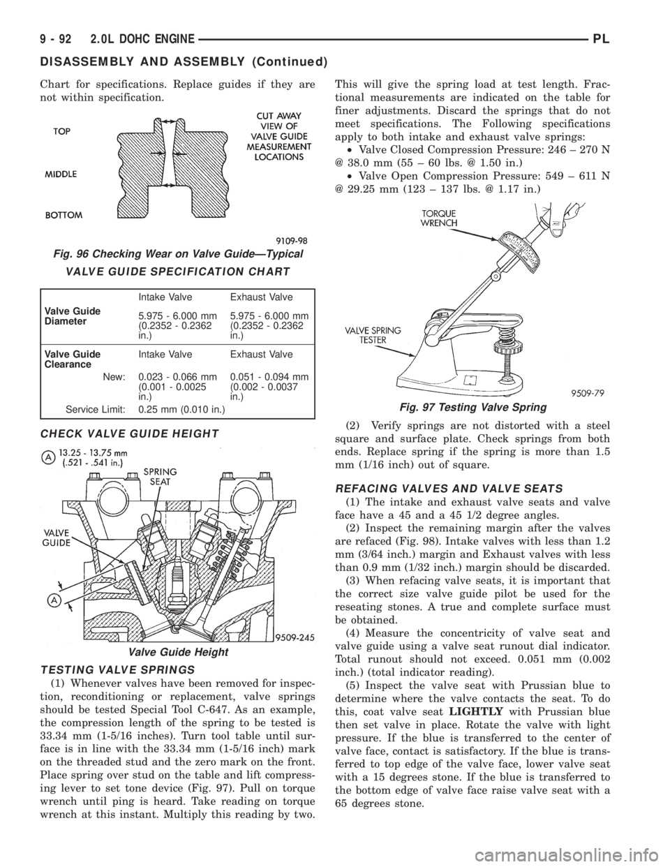
Chart for specifications. Replace guides if they are
not within specification.
CHECK VALVE GUIDE HEIGHT
TESTING VALVE SPRINGS
(1) Whenever valves have been removed for inspec-
tion, reconditioning or replacement, valve springs
should be tested Special Tool C-647. As an example,
the compression length of the spring to be tested is
33.34 mm (1-5/16 inches). Turn tool table until sur-
face is in line with the 33.34 mm (1-5/16 inch) mark
on the threaded stud and the zero mark on the front.
Place spring over stud on the table and lift compress-
ing lever to set tone device (Fig. 97). Pull on torque
wrench until ping is heard. Take reading on torque
wrench at this instant. Multiply this reading by two.This will give the spring load at test length. Frac-
tional measurements are indicated on the table for
finer adjustments. Discard the springs that do not
meet specifications. The Following specifications
apply to both intake and exhaust valve springs:
²Valve Closed Compression Pressure: 246 ± 270 N
@ 38.0 mm (55 ± 60 lbs. @ 1.50 in.)
²Valve Open Compression Pressure: 549 ± 611 N
@ 29.25 mm (123 ± 137 lbs. @ 1.17 in.)
(2) Verify springs are not distorted with a steel
square and surface plate. Check springs from both
ends. Replace spring if the spring is more than 1.5
mm (1/16 inch) out of square.
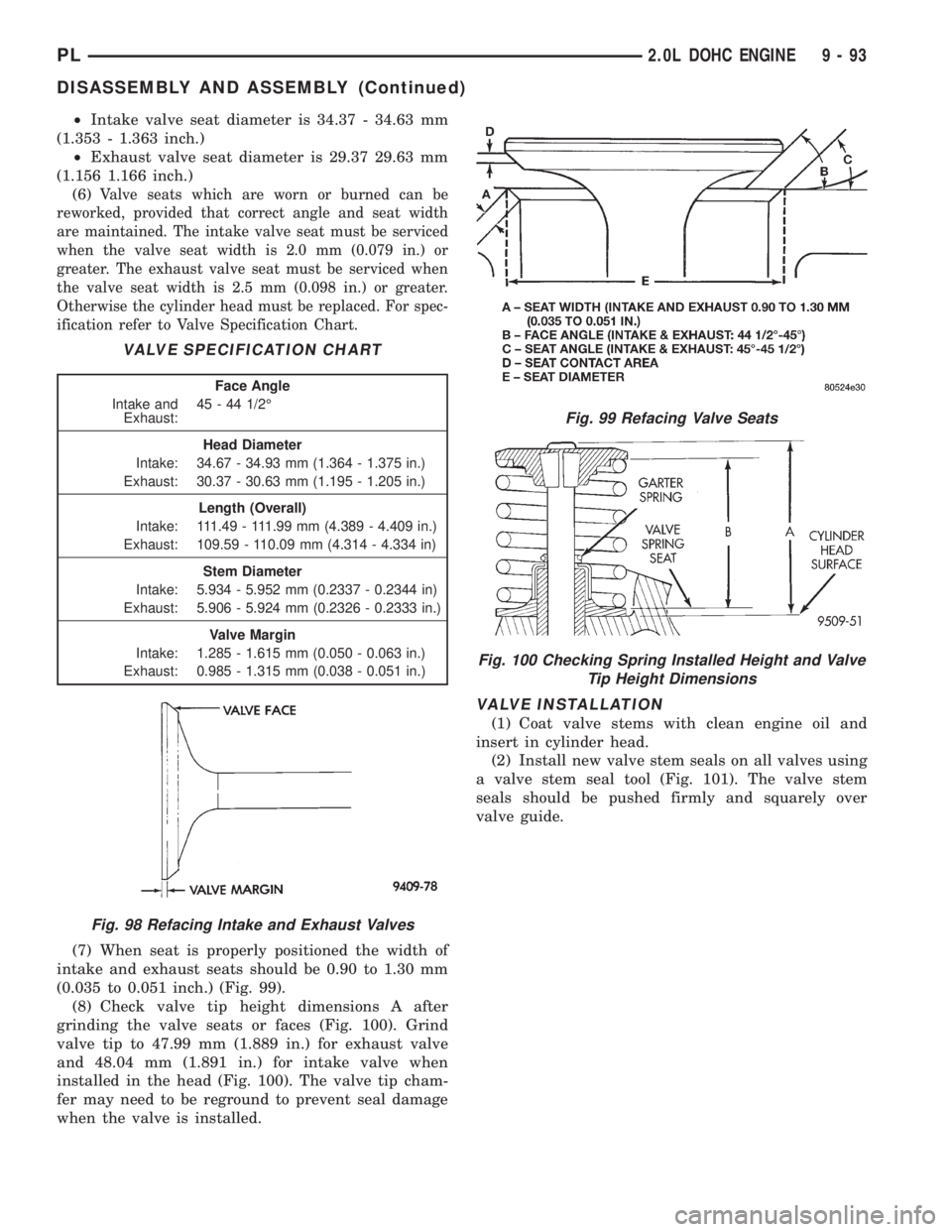
REFACING VALVES AND VALVE SEATS
(1) The intake and exhaust valve seats and valve
face have a 45 and a 45 1/2 degree angles.
(2) Inspect the remaining margin after the valves
are refaced (Fig. 98). Intake valves with less than 1.2
mm (3/64 inch.) margin and Exhaust valves with less
than 0.9 mm (1/32 inch.) margin should be discarded.
(3) When refacing valve seats, it is important that
the correct size valve guide pilot be used for the
reseating stones. A true and complete surface must
be obtained.
(4) Measure the concentricity of valve seat and
valve guide using a valve seat runout dial indicator.
Total runout should not exceed. 0.051 mm (0.002
inch.) (total indicator reading).
(5) Inspect the valve seat with Prussian blue to
determine where the valve contacts the seat. To do
this, coat valve seatLIGHTLYwith Prussian blue
then set valve in place. Rotate the valve with light
pressure. If the blue is transferred to the center of
valve face, contact is satisfactory. If the blue is trans-
ferred to top edge of the valve face, lower valve seat
with a 15 degrees stone. If the blue is transferred to
the bottom edge of valve face raise valve seat with a
65 degrees stone.
Fig. 96 Checking Wear on Valve GuideÐTypical
VALVE GUIDE SPECIFICATION CHART
Valve Guide
DiameterIntake Valve Exhaust Valve
5.975 - 6.000 mm
(0.2352 - 0.2362
in.)5.975 - 6.000 mm
(0.2352 - 0.2362
in.)
Valve Guide
ClearanceIntake Valve Exhaust Valve
New: 0.023 - 0.066 mm
(0.001 - 0.0025
in.)0.051 - 0.094 mm
(0.002 - 0.0037
in.)
Service Limit: 0.25 mm (0.010 in.)
Valve Guide Height
Fig. 97 Testing Valve Spring
9 - 92 2.0L DOHC ENGINEPL
DISASSEMBLY AND ASSEMBLY (Continued)
Page 806 of 1200
²Intake valve seat diameter is 34.37 - 34.63 mm
(1.353 - 1.363 inch.)
²Exhaust valve seat diameter is 29.37 29.63 mm
(1.156 1.166 inch.)
(6)
Valve seats which are worn or burned can be
reworked, provided that correct angle and seat width
are maintained. The intake valve seat must be serviced
when the valve seat width is 2.0 mm (0.079 in.) or
greater. The exhaust valve seat must be serviced when
the valve seat width is 2.5 mm (0.098 in.) or greater.
Otherwise the cylinder head must be replaced. For spec-
ification refer to Valve Specification Chart.
(7) When seat is properly positioned the width of
intake and exhaust seats should be 0.90 to 1.30 mm
(0.035 to 0.051 inch.) (Fig. 99).
(8) Check valve tip height dimensions A after
grinding the valve seats or faces (Fig. 100). Grind
valve tip to 47.99 mm (1.889 in.) for exhaust valve
and 48.04 mm (1.891 in.) for intake valve when
installed in the head (Fig. 100). The valve tip cham-
fer may need to be reground to prevent seal damage
when the valve is installed.
VALVE INSTALLATION
(1) Coat valve stems with clean engine oil and
insert in cylinder head.
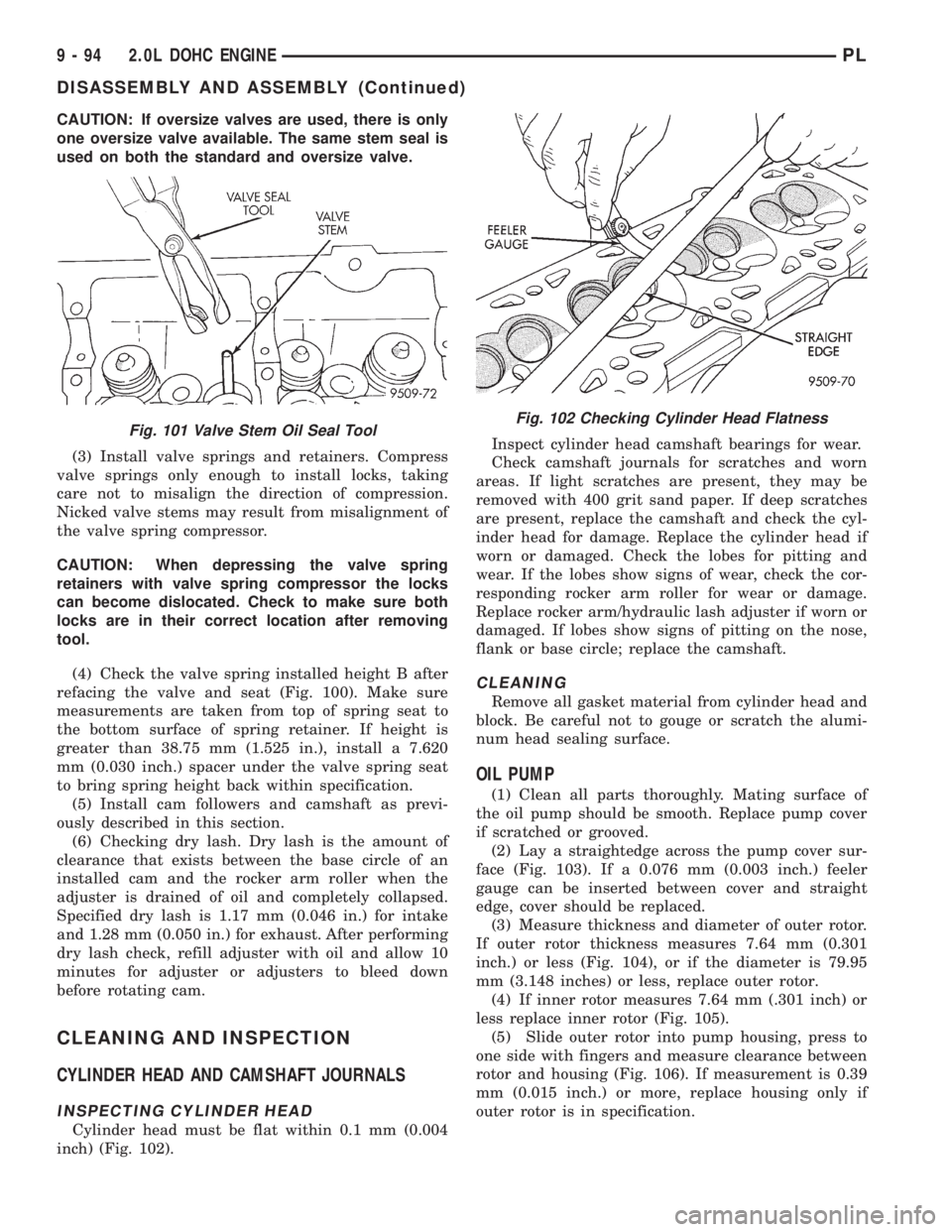
(2) Install new valve stem seals on all valves using
a valve stem seal tool (Fig. 101). The valve stem
seals should be pushed firmly and squarely over
valve guide.
VALVE SPECIFICATION CHART
Face Angle
Intake and
Exhaust:45 - 44 1/2É
Head Diameter
Intake: 34.67 - 34.93 mm (1.364 - 1.375 in.)
Exhaust: 30.37 - 30.63 mm (1.195 - 1.205 in.)
Length (Overall)
Intake: 111.49 - 111.99 mm (4.389 - 4.409 in.)
Exhaust: 109.59 - 110.09 mm (4.314 - 4.334 in)
Stem Diameter
Intake: 5.934 - 5.952 mm (0.2337 - 0.2344 in)
Exhaust: 5.906 - 5.924 mm (0.2326 - 0.2333 in.)
Valve Margin
Intake: 1.285 - 1.615 mm (0.050 - 0.063 in.)
Exhaust: 0.985 - 1.315 mm (0.038 - 0.051 in.)
Fig. 98 Refacing Intake and Exhaust Valves
Fig. 99 Refacing Valve Seats
Fig. 100 Checking Spring Installed Height and Valve
Tip Height Dimensions
PL2.0L DOHC ENGINE 9 - 93
DISASSEMBLY AND ASSEMBLY (Continued)
Page 807 of 1200
CAUTION: If oversize valves are used, there is only
one oversize valve available. The same stem seal is
used on both the standard and oversize valve.
(3) Install valve springs and retainers. Compress
valve springs only enough to install locks, taking
care not to misalign the direction of compression.
Nicked valve stems may result from misalignment of
the valve spring compressor.
CAUTION: When depressing the valve spring
retainers with valve spring compressor the locks
can become dislocated. Check to make sure both
locks are in their correct location after removing
tool.
(4) Check the valve spring installed height B after
refacing the valve and seat (Fig. 100). Make sure
measurements are taken from top of spring seat to
the bottom surface of spring retainer. If height is
greater than 38.75 mm (1.525 in.), install a 7.620
mm (0.030 inch.) spacer under the valve spring seat
to bring spring height back within specification.
(5) Install cam followers and camshaft as previ-
ously described in this section.
(6) Checking dry lash. Dry lash is the amount of
clearance that exists between the base circle of an
installed cam and the rocker arm roller when the
adjuster is drained of oil and completely collapsed.
Specified dry lash is 1.17 mm (0.046 in.) for intake
and 1.28 mm (0.050 in.) for exhaust. After performing
dry lash check, refill adjuster with oil and allow 10
minutes for adjuster or adjusters to bleed down
before rotating cam.
CLEANING AND INSPECTION
CYLINDER HEAD AND CAMSHAFT JOURNALS
INSPECTING CYLINDER HEAD
Cylinder head must be flat within 0.1 mm (0.004
inch) (Fig. 102).Inspect cylinder head camshaft bearings for wear.
Check camshaft journals for scratches and worn
areas. If light scratches are present, they may be
removed with 400 grit sand paper. If deep scratches
are present, replace the camshaft and check the cyl-
inder head for damage. Replace the cylinder head if
worn or damaged. Check the lobes for pitting and
wear. If the lobes show signs of wear, check the cor-
responding rocker arm roller for wear or damage.
Replace rocker arm/hydraulic lash adjuster if worn or
damaged. If lobes show signs of pitting on the nose,
flank or base circle; replace the camshaft.
CLEANING
Remove all gasket material from cylinder head and
block. Be careful not to gouge or scratch the alumi-
num head sealing surface.
OIL PUMP
(1) Clean all parts thoroughly. Mating surface of
the oil pump should be smooth. Replace pump cover
if scratched or grooved.
(2) Lay a straightedge across the pump cover sur-
face (Fig. 103). If a 0.076 mm (0.003 inch.) feeler
gauge can be inserted between cover and straight
edge, cover should be replaced.
(3) Measure thickness and diameter of outer rotor.
If outer rotor thickness measures 7.64 mm (0.301
inch.) or less (Fig. 104), or if the diameter is 79.95
mm (3.148 inches) or less, replace outer rotor.
(4) If inner rotor measures 7.64 mm (.301 inch) or
less replace inner rotor (Fig. 105).
(5) Slide outer rotor into pump housing, press to
one side with fingers and measure clearance between
rotor and housing (Fig. 106). If measurement is 0.39
mm (0.015 inch.) or more, replace housing only if
outer rotor is in specification.
Fig. 101 Valve Stem Oil Seal ToolFig. 102 Checking Cylinder Head Flatness
9 - 94 2.0L DOHC ENGINEPL
DISASSEMBLY AND ASSEMBLY (Continued)
Page 808 of 1200
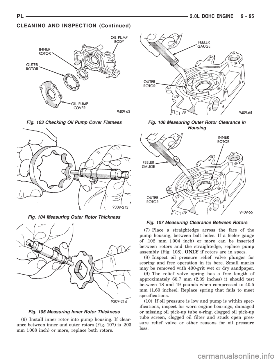
(6) Install inner rotor into pump housing. If clear-
ance between inner and outer rotors (Fig. 107) is .203
mm (.008 inch) or more, replace both rotors.(7) Place a straightedge across the face of the
pump housing, between bolt holes. If a feeler gauge
of .102 mm (.004 inch) or more can be inserted
between rotors and the straightedge, replace pump
assembly (Fig. 108).ONLYif rotors are in specs.
(8) Inspect oil pressure relief valve plunger for
scoring and free operation in its bore. Small marks
may be removed with 400-grit wet or dry sandpaper.
(9) The relief valve spring has a free length of
approximately 60.7 mm (2.39 inches) it should test
between 18 and 19 pounds when compressed to 40.5
mm (1.60 inches). Replace spring that fails to meet
specifications.
(10) If oil pressure is low and pump is within spec-
ifications, inspect for worn engine bearings, damaged
or missing oil pick-up tube o-ring, clogged oil pick-up
tube screen, clogged oil filter and stuck open pres-
sure relief valve or other reasons for oil pressure
loss.
Fig. 103 Checking Oil Pump Cover Flatness
Fig. 104 Measuring Outer Rotor Thickness
Fig. 105 Measuring Inner Rotor Thickness
Fig. 106 Measuring Outer Rotor Clearance in
Housing
Fig. 107 Measuring Clearance Between Rotors
PL2.0L DOHC ENGINE 9 - 95
CLEANING AND INSPECTION (Continued)
Page 809 of 1200
CYLINDER BLOCK AND BORE
(1) Clean cylinder block thoroughly and check all
core hole plugs for evidence of leaking.
(2) If new core plugs are installed, Refer to Engine
Core Plugs outlined in this section.
(3) Examine block and cylinder bores for cracks or
fractures.
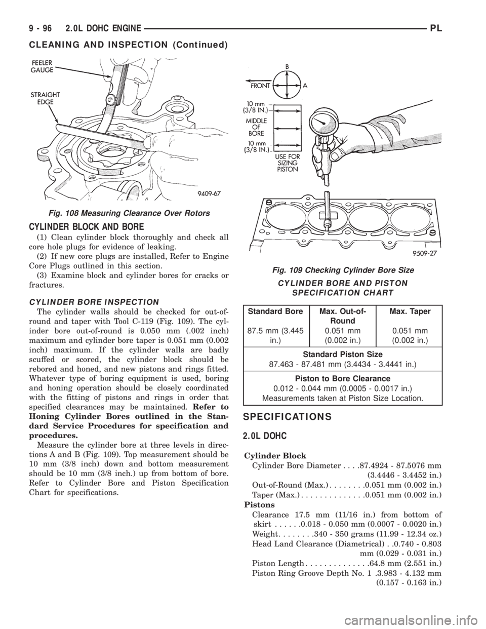
CYLINDER BORE INSPECTION
The cylinder walls should be checked for out-of-
round and taper with Tool C-119 (Fig. 109). The cyl-
inder bore out-of-round is 0.050 mm (.002 inch)
maximum and cylinder bore taper is 0.051 mm (0.002
inch) maximum. If the cylinder walls are badly
scuffed or scored, the cylinder block should be
rebored and honed, and new pistons and rings fitted.
Whatever type of boring equipment is used, boring
and honing operation should be closely coordinated
with the fitting of pistons and rings in order that
specified clearances may be maintained.Refer to
Honing Cylinder Bores outlined in the Stan-
dard Service Procedures for specification and
procedures.
Measure the cylinder bore at three levels in direc-
tions A and B (Fig. 109). Top measurement should be
10 mm (3/8 inch) down and bottom measurement
should be 10 mm (3/8 inch.) up from bottom of bore.
Refer to Cylinder Bore and Piston Specification
Chart for specifications.
SPECIFICATIONS
2.0L DOHC
Cylinder Block
Cylinder Bore Diameter. . . .87.4924 - 87.5076 mm
(3.4446 - 3.4452 in.)
Out-of-Round (Max.)........0.051 mm (0.002 in.)
Taper (Max.)..............0.051 mm (0.002 in.)
Pistons
Clearance 17.5 mm (11/16 in.) from bottom of
skirt......0.018 - 0.050 mm (0.0007 - 0.0020 in.)
Weight........340 - 350 grams (11.99 - 12.34 oz.)
Head Land Clearance (Diametrical) . .0.740 - 0.803
mm (0.029 - 0.031 in.)
Piston Length..............64.8 mm (2.551 in.)
Piston Ring Groove Depth No. 1 .3.983 - 4.132 mm
(0.157 - 0.163 in.)
Fig. 108 Measuring Clearance Over Rotors
Fig. 109 Checking Cylinder Bore Size
CYLINDER BORE AND PISTON
SPECIFICATION CHART
Standard Bore Max. Out-of-
RoundMax. Taper
87.5 mm (3.445
in.)0.051 mm
(0.002 in.)0.051 mm
(0.002 in.)
Standard Piston Size
87.463 - 87.481 mm (3.4434 - 3.4441 in.)
Piston to Bore Clearance
0.012 - 0.044 mm (0.0005 - 0.0017 in.)
Measurements taken at Piston Size Location.
9 - 96 2.0L DOHC ENGINEPL
CLEANING AND INSPECTION (Continued)
Page 810 of 1200
Piston Ring Groove Depth No. 2 .4.456 - 4.605 mm
(0.175 - 0.181 in.)
Piston Ring Groove Depth No. 3 .3.841 - 4.075 mm
(0.151 - 0.160 in.)
Piston Pins
Clearance in Piston. . . .0.008 - 0.020 mm (0.0003 -
0.0008 in.)
In Rod (Interference) . . .0.018 - 0.043 mm (0.0007 -
0.0017 in.)
Diameter .20.998 - 21.003 mm (0.8267 - 0.8269 in.)
End Play.............................None
Length.......74.75 - 75.25 mm (2.943 - 2.963 in.)
Piston Rings
Ring Gap Top Compression Ring . . .0.23 - 0.52 mm
(0.009 - 0.020 in.)
Ring Gap 2nd Compression Ring . . .0.49 - 0.78 mm
(0.019 - 0.031 in.)
Ring Gap Oil Control (Steel Rails). .0.23 - 0.66 mm
(0.009 - 0.026 in.)
Ring Side Clearance Both
Compression Rings. . . .0.025 - 0.065 mm (0.0010 -
0.0026 in.)
Oil Ring (Pack).0.004 - 0.178 mm (0.0002 - 0.0070 in.)
Ring Width Compression Rings. . . .1.17 - 1.19 mm
(0.046 - 0.047 in.)
Oil Ring (Pack).2.854 - 3.008 mm (0.1124 - 0.1184 in.)
Connecting Rod
Bearing Clearance.0.026 - 0.059 mm (0.001 - 0.0023
in.)
Piston Pin Bore Diameter.20.96 - 20.98 mm (0.8252
- 0.8260 in.)
Large End Bore Diameter. . . .50.991 - 51.005 mm
(2.0075 - 2.0081 in.)
Side Clearance . .0.13 - 0.38 mm (0.005 - 0.015 in.)
Total Weight (Less Bearing) . .543 grams (1.20 lbs.)
Crankshaft
Connecting Rod Journal Diameter.47.9924 - 48.0076
mm (1.8894 - 1.8900 in.)
Out-of-Round (Max.)......0.0035 mm (0.0001 in.)
Taper (Max.)............0.0038 mm (0.0001 in.)
Main Bearing Diametrical
Clearance No. 1 - 5.0.022 - 0.062 mm (0.0008 - 0.0024
in.)
End Play.....0.09 - 0.24 mm (0.0035 - 0.0094 in.)
Main Bearing Journals
Diameter.51.9924 - 52.0076 mm (2.0469 - 2.0475 in.)
Out-of-Round (Max.)......0.0035 mm (0.0001 in.)
Taper (Max.)............0.0038 mm (0.0001 in.)
Camshaft
Bearing Bore Diameter No. 1 - 6.26.020 mm - 26.041
mm (1.024 - 1.025 in.)
Diametrical Bearing Clearance . .0.069 - 0.071 mm
(0.0027 - 0.003 in.)
End Play.......0.05 - 0.15 mm (0.002 - 0.006 in.)Bearing Journal Diameter No. 1 - 6.25.951 - 25.970
mm (1.021 - 1.022 in.)
Lift (Zero Lash) Intake.......8.75 mm (0.344 in.)
Lift (Zero Lash) Exhaust.....8.00 mm (0.314 in.)
Valve Timing @ .5 mm Lift
Intake Valve Closes (ABDC)...............38É
Intake Valve Opens (BTDC)...............1.2É
Intake Valve Duration..................219.2É
Exhaust Valve Closes (BTDC)...............3É
Exhaust Valve Opens (BBDC)..............42É
Exhaust Valve Duration..................219É
Valve Overlap...........................0É
Cylinder Head
Material.....................Cast Aluminum
Gasket Thickness (Compressed).1.15 mm (0.045 in.)
Valve Seat Angle...................44.5 - 45É
Runout (Max.).............0.050 mm (0.002 in.)
Width (Finished) Intake and Exhaust .0.9 - 1.3 mm
(0.035 - 0.051 in.)
Valve Guide Finished Diameter ID.5.975 - 6.000 mm
(0.235 - 0.236 in.)
Guide Bore Diameter (Standard) . .11.0 - 11.02 mm
(0.4330 - 0.4338 in.)
Valves
Head Diameter Intake . .34.67 - 34.93 mm (1.365 -
1.375 in.)
Head Diameter Exhaust .30.37 - 30.36 mm (1.195 -
1.195 in.)
Valve Margin Intake.1.15 - 1.48 mm (0.0452 - 0.0582
in.)
Valve Margin Exhaust . .1.475 - 1.805 mm (0.058 -
0.071 in.)
Length Intake.111.49 -111.99 mm (4.389 - 4.409 in.)
Length Exhaust .109.59 - 110.09 mm (4.314 - 4.334
in.)
Valve Stem Tip Heigth Intake.48.04 mm (1.891 in.)
Valve Stem Tip Heigth Exhaust.47.99 mm (1.889 in.)
Stem Diameter Intake. .5.9034 - 5.952 mm (0.234 -
0.234 in.)
Stem Diameter Exhaust .5.906 - 5.924 mm (0.233 -
0.233 in.)
Stem-to-Guide Clearance Intake .0.023 - 0.066 mm
(0.0009 - 0.0025 in.)
Stem-to-Guide Clearance Exhaust.0.051 - 0.094 mm
(0.002 - 0.0037 in.)
Maximum Allowable Intake . .0.076 mm (0.003 in.)
Maximum Allowable Exhaust .0.101 mm (0.004 in.)
Valve Spring
Free Length (Approx.).........46mm(1.811 in.)
Spring Tension (Valve Closed).246 - 270 N @ 38.0 mm
(55 - 60 lbs. @ 1.496 in.)
Spring Tension (Valve Open).549 - 611 N @ 29.3 mm
(123 - 137 lbs. @ 1.53 in.)
PL2.0L DOHC ENGINE 9 - 97
SPECIFICATIONS (Continued)