FORD MUSTANG 1969 Volume One Chassis
Manufacturer: FORD, Model Year: 1969, Model line: MUSTANG, Model: FORD MUSTANG 1969Pages: 413, PDF Size: 75.81 MB
Page 91 of 413
03-02-15
Suspension
03-02-15
BUSHING
BUSHING
WASHER
BOLT
K5s»
LOCKWASHER
STRUT
NUT
;Y'0lT-ÂŁii *
' N
WASHER
>*V ©"*
LOCKWASHER #
NUT
SHER/
©^—
SLOWER
ARM
ASSY.
«
^PLUG
INSULATOR
WASHER
NUT
NUT
F1221-B
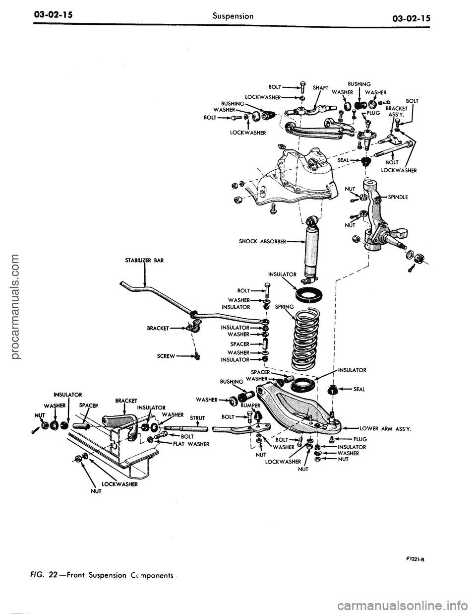
FIG. 22—Front Suspension Componentsprocarmanuals.com
Page 92 of 413
03-02-16
Suspension
03-02-16
2.
Place a jack under the outer end
of the arm.
3.
Tape the upper and lower spring
insulators to the spring.
4.
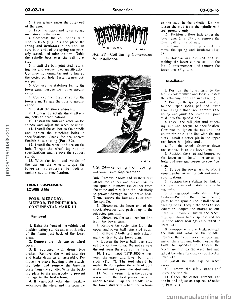
Compress the coil spring with
Tool 5310-A (Fig. 23) and place the
spring and insulators in position. Be
sure both ends of the spring are prop-
erly seated, and raise the arm. Guide
the spindle boss over the ball joint
stud.
5.
Install the ball joint stud retain-
ing nut and torque it to specification.
Continue tightening the nut to line up
the cotter pin hole. Install a new cot-
ter pin.
6. Connect the stabilizer bar to the
lower arm. Torque the nut to specifi-
cation.
7.
Connect the drag strut to the
lower arm. Torque the nuts to specifi-
cation.
8. Install the shock absorber.
9. Tighten the splash shield attach-
ing bolts to specifications.
10.
Install the hub and rotor on the
spindle and adjust the wheel bearings.
11.
Install the caliper to the spindle
and tighten the attaching bolts to
specifications. Check for the correct
flexible hose routing (Part 2-2).
12.
Install the wheel and tire on the
hub.
Torque the wheel lug nuts to
specifications and remove the support
stands.
13.
With the front end weight of
the car on the wheels, torque the
lower arm-to-crossmember bolt at-
taching nut to specification.
FRONT SUSPENSION
LOWER ARM
FORD, MERCURY,
METEOR, THUNDERBIRD,
CONTINENTAL MARK III
Removal
1.
Raise the front of the vehicle and
position safety stands under both sides
of the frame just back of the lower
arms.
2.
Remove the hub cap or wheel
cover.
3.
If equipped with drum type
brakes—Remove the wheel and tire
and brake drum as an assembly. Re-
move the brake backing plate attach-
ing bolts and remove the backing
plate from the spindle. Wire the back-
ing plate to the underbody to prevent
damage to the brake hose.
4.
If equipped with disc brakes-
—Remove the wheel and tire from the
•Tool—5310-A
F 1491-A
FIG. 23—Coil Spring Compressed
for Installation
F1437-A
FIG. 24—Removing Front Spring
—Lower Arm Replacement
hub.
Remove 2 bolts and washers that
attach the caliper and brake hose to
the spindle. Remove the caliper from
the rotor and wire it to the underbody
to prevent damage to the brake hose.
Then, remove the hub and rotor from
the spindle.
5.
Disconnect the lower end of the
shock absorber, and push it up to the
retracted position.
6. Disconnect the stabilizer bar link
from the lower arm.
7.
Remove the cotter pins from the
upper and lower ball joint stud nuts.
8. Remove 2 bolts and nuts attach-
ing the strut to the lower arm.
9. Loosen the lower ball joint stud
nut one or two turns. Do not remove
the nut from the stud at this time.
10.
Install Tool T57P-3OO6-A bet-
ween the upper and lower ball joint
studs (Fig. 7). The tool should be
seated firmly against the ends of both
studs and not against the stud nuts.
11.
With a wrench, turn the adapter
screw until the tool places the stud
under tension. Tap the spindle near
the lower stud with a hammer to loos-
en the stud in the spindle. Do not
loosen the stud from the spindle with
tool pressure only.
12.
Position a floor jack under the
lower arm (Fig. 24) and remove the
lower ball joint stud nut.
13.
Lower the floor jack and re-
move the sprina and insulator (Fie.
25).
14.
Remove one nut and bolt at-
taching the lower control arm to the
No.
2 crossmember and remove the
lower arm (Fig. 24).
Installation
1.
Position the lower arm to the
No.
2 crossmember and loosely install
the attaching bolt and nut (Fig. 1).
2.
Position the spring and insulator
to the upper spring pad and lower
arm. Using a floor jack, compress the
spring and guide the lower ball joint
stud into the spindle hole.
3.
Install the ball joint stud attach-
ing nut and torque to specification.
Continue to tighten the nut until the
cotter pin hole is in line with the nut
slots.
Install a cotter pin in the upper
and lower ball joint studs.
4.
Pull the shock absorber down
and connect it to the lower arm.
5.
Position the strut and bumper to
the lower arm. Install the attaching
bolts and nuts and torque to specifica-
tion.
6. Torque the lower arm to No. 2
crossmember attaching bolt and nut to
specifications.
7.
Position the stabilizer bar link to
the lower arm and install the attach-
ing nuts.
8. If equipped with drum type
brakes—Position the brake backing
plate to the spindle and install the at-
taching bolts. Torque the bolts to spe-
cification. Adjust the brakes as out-
lined in Group 2. Install the wheel,
tire,
and drum to the spindle and ad-
just the wheel bearings as outlined in
Part 3-12.
If equipped with disc brakes-Install
the hub and rotor on the spindle.
Position the caliper over the rotor and
install the attaching bolts. Torque the
bolts to specification. Install the
wheel and tire on the wheel hub and
adjust the wheel bearings as outlined in
Part 3-12.
9. Install the hub cap or wheel
cover.
10.
Remove the safety stands and'
lower the vehicle.
11.
Check the caster, camber, and
toe-in and adjust as required (Section
2,
Part 3-1).procarmanuals.com
Page 93 of 413
03-02-17
Suspension
03-02-17
BOLT
REAR
ADJUSTMENT
5A486
NUT
BUSHING
OUTER
SLEEVE
3A187 3B282
CASTELLATED
FRONT
ADJUSTMENT
NUT
NUT
LOWER BALL JOINT
3042
F
1152-
E
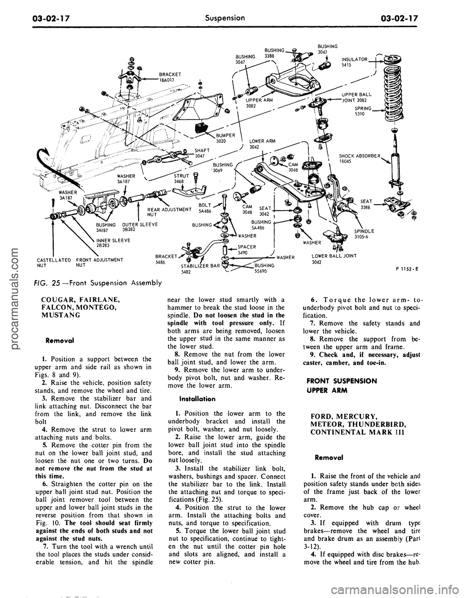
FIG.
25—
Front
Suspension Assembly
COUGAR, FAIRLANE,
FALCON, MONTEGO,
MUSTANG
Removal
1.
Position a support between the
upper arm and side rail as shown in
Figs.
8 and 9).
2.
Raise the vehicle, position safety
stands,
and remove the wheel and tire.
3.
Remove the stabilizer bar and
link attaching nut. Disconnect the bar
from the link, and remove the link
bolt
4.
Remove the strut to lower arm
attaching nuts and bolts.
5.
Remove the cotter pin from the
nut on the lower ball joint stud, and
loosen the nut one or two turns. Do
not
remove the nut from the stud at
this
time.
6.
Straighten the cotter pin on the
upper ball joint stud nut. Position the
ball joint remover tool between the
upper and lower ball joint studs in the
reverse position from that shown in
Fig.
10. The tool should seat firmly
against the ends of both studs and not
against the stud nuts.
7.
Turn the tool with a wrench until
the tool places the studs under consid-
erable tension, and hit the spindle
near the lower stud smartly with a
hammer to break the stud loose in the
spindle. Do not loosen the stud in the
spindle with tool pressure only. If
both arms are being removed, loosen
the upper stud in the same manner as
the lower stud.
8. Remove the nut from the lower
ball joint stud, and lower the arm.
9. Remove the lower arm to under-
body pivot bolt, nut and washer. Re-
move the lower arm.
Installation
1.
Position the lower arm to the
underbody bracket and install the
pivot bolt, washer, and nut loosely.
2.
Raise the lower arm, guide the
lower ball joint stud into the spindle
bore,
and install the stud attaching
nut loosely.
3.
Install the stabilizer link bolt,
washers,
bushings and spacer. Connect
the stabilizer bar to the link. Install
the attaching nut and torque to speci-
fications (Fig. 25).
4.
Position the strut to the lower
arm. Install the attaching bolts and
nuts,
and torque to specification.
5.
Torque the lower ball joint stud
nut to specification, continue to tight-
en the nut until the cotter pin hole
and slots are aligned, and install a
new cotter pin.
6. Torque the lower arm- to
underbody pivot bolt and nut to speci-
fication.
7.
Remove the safety stands and
lower the vehicle.
8. Remove the support from be-
tween the upper arm and frame.
9.
Check and, if necessary, adjust
caster, camber, and toe-in.
FRONT
SUSPENSION
UPPER
ARM
FORD,
MERCURY,
METEOR,
THUNDERBIRD,
CONTINENTAL
MARK III
Removal
1.
Raise the front of the vehicle and
position safety stands under both sides
of the frame just back of the lower
arm.
2.
Remove the hub cap or wheel
cover.
3.
If equipped with drum type
brakes—remove the wheel and tire
and brake drum as an assembly (Part
3-12).
4.
If equipped with disc brakes—re-
move the wheel and tire from the hub.procarmanuals.com
Page 94 of 413
03-02-18
Suspension
03-02-18
5.
Remove the cotter pin from the
upper ball joint stud nut.
6. Loosen the upper ball joint stud
nut one or two turns. Do not remove
the nut from the stud at this time.
7.
Install tool T57P-3006-A be-
tween the upper and lower ball joint
studs with the adapter screw on top
(Fig. 13). The tool should be seated
firmly against the ends of both studs
and not against the nuts or lower stud
cotter pin.
8. With a wrench, turn the adapter
screw until the tool places the stua
under tension. Tap the spindle near
the upper stud with a hammer to loos-
en the stud in the spindle. Do not
loosen the stud from the spindle with
tool pressure only.
9. Remove the tool from between
the ball joint studs and place a floor
jack under the lower arm.
10.
Raise the floor jack to relieve
the pressure from the upper ball joint
stud nut and remove the nut.
11.
Remove the upper arm inner
shaft attaching bolts. Remove the
upper arm and inner shaft as an as-
sembly (Fig. 1).
12.
Remove the bumpei from the
upper arm.
Installation
1.
Position the bumper to the upper
arm and install the nut and washer.
Torque the nut to specifications.
2.
Position the upper arm inner
shaft to the frame side rail and install
the 2 attaching bolts and washers
snug.
3.
Connect the upper ball joint stud
to the spindle and install the attaching
nut. Torque the nut to specification
and continue to tighten the nut until
the cotter pin hole in the stud is in
line with the nut slots. Then, install
the cotter pin.
4.
If equipped with drum type bra-
kes—Adjust the brakes as outlined in
Part 2-2. Install the wheel, tire, and
drum to the spindle and adjust the
wheel bearings as outlined in Part
3-12.
5.
If equipped with disc brak-
es—Install the wheel and tire on the
hub and adjust the wheel bearings as
outlined in Part 3-12.
6. Install the hub cap or wheel
cover.
7.
Remove the safety stands and
lower the front of the vehicle.
8. Check caster, camber, and toe-in
and adjust as required (Section 2, Part
3-D.
COUGAR, FAIRLANE,
FALCON, MONTEGO,
MUSTANG
Removal
1.
Raise the front of the vehicle,
position safety stands under the
frame, and lower the vehicle slightly.
2.
Remove the wheel and tire.
3.
Remove the shock absorber
lower attaching nuts and washers.
4.
Remove the shock absorber
upper mounting bracket attaching
nuts,
and remove the shock absorber
and bracket as an assembly (Fig. 26).
On all 8-cylinder vehicles, remove
the air cleaner to obtain access for
tool installation.
5.
Install the spring compressor
tool and compress the spring (Figs.
19,
20 and 21).
6. Position a safety stand under the
lower arm.
7.
Remove the cotter pin from the
nut on the upper ball joint stud, and
loosen the nut one or two turns. Do
not remove the nut from the stud at
this time.
8. Position the ball joint remover
tool between the upper and lower ball
joint studs as shown in Fig. 10. The
tool should seat firmly against the
ends of both studs and not against the
stud nuts.
9. Turn the tool with a wrench until
the tool places the studs under consid-
erable tension; then, hit the spindle
smartly near the upper stud with a
hammer to break the stud loose in the
spindle. Do not loosen the stud in the
spindle with tool pressure only. If
both arms are being removed, loosen
the lower stud in the same manner as
the upper stud.
10.
Remove the nut from the upper
stud and lift the stud out of the
spindle.
11.
Remove the upper arm inner
shaft attaching nuts from the engine
compartment, and remove the upper
arm.
12.
Wipe off all loose dirt from the
upper arm parts. Do not wash the ball
joint with a solvent.
Installation
1.
Position the upper arm on the
underbody mounting bracket, and in-
stall the nuts and lock washers on the
two inner shaft attaching bolts. The
specified keystone-type lock washers
must be used. Torque the nuts to
soecification.
2.
Position the upper ball joint stud
in the top of the wheel spindle, and in-
stall the stud nut. Torque the nut to
specification, and continue to tighten
it until the cotter pin hole and slots
line up. Install a new cotter pin.
3.
Release the coil spring, remove
the tool, and install the front shock
absorber and the wheel and tire.
LINCOLN CONTINENTAL
Removal
1.
Place a jack under the outer end
of the suspension lower arm and raise
the arm. Refer to Fig. 22.
2.
Remove the wheel and tire.
3.
Remove the cotter pin from the
upper ball joint stud. Loosen the nut
one or two turns.
4.
Place a box wrench over the
lower end of the ball joint remover
tool, and position the tool as in Fig.
13.
The tool should seat firmly against
the ends of both studs, and not
against the upper stud nut.
5.
Turn the wrench until both studs
are under tension, and then, tap the
spindle with a hammer near the upper
stud to loosen it from the spindle. Do
not loosen the stud with tool pressure
alone. Remove the nut.
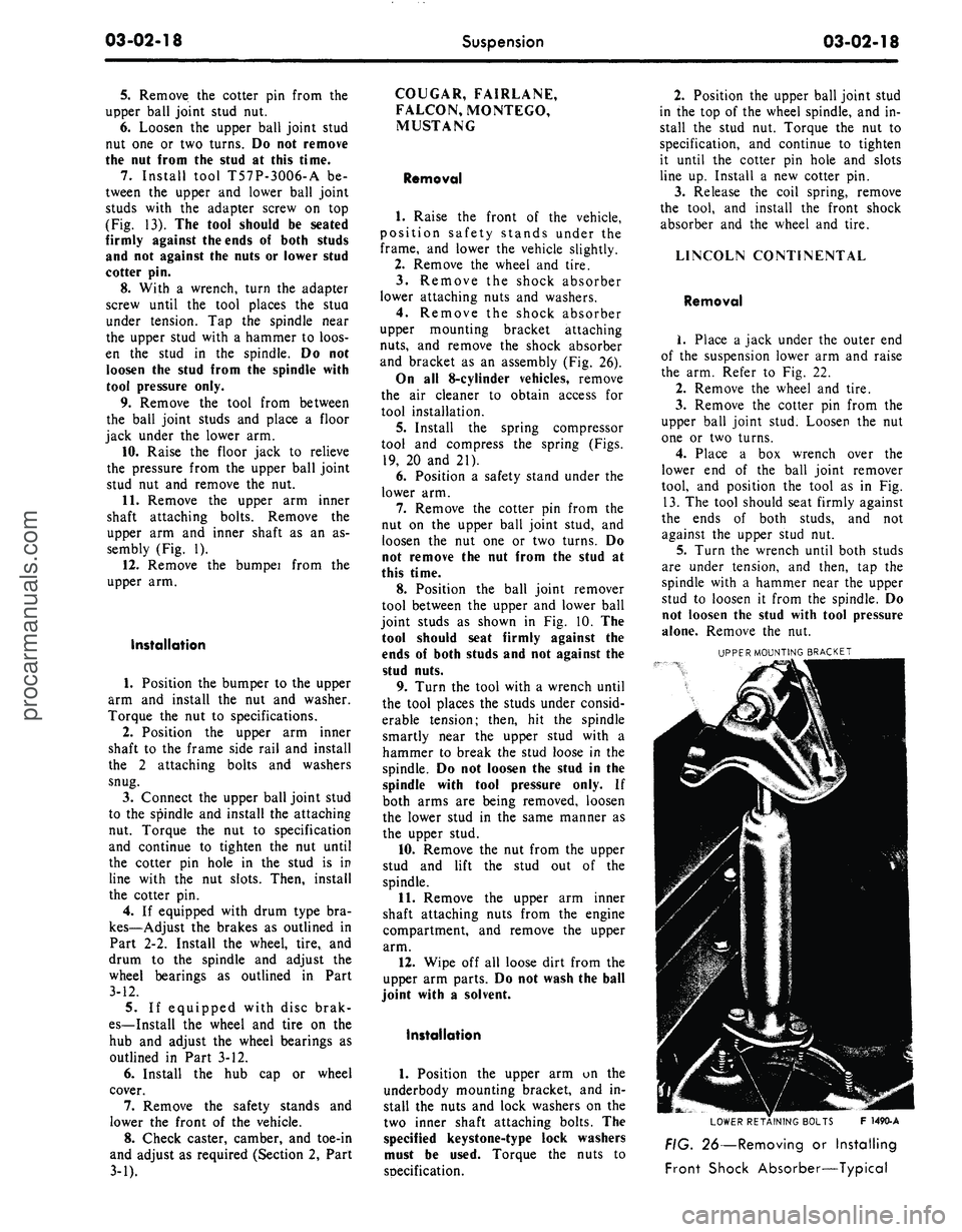
UPPER MOUNTING BRACKET
LOWER RETAINING BOLTS F 1490-A
FIG. 26—Removing or Installing
Front Shock Absorber—Typicalprocarmanuals.com
Page 95 of 413
03-02-19
Suspension
03-02-19
6. Raise the upper arm to free the
ball joint stud from the spindle. Wire
the upper end of the spindle to the un-
derbody to prevent damage to the
brake hose.
7.
Mark the position of the upper
arm shaft on the underbody member
to facilitate making caster and camber
adjustments after installation of the
upper arm.
8. Remove the suspension upper
arm-to-underbody attaching bolts,
lock washers, and attaching nuts.
Then, remove the upper arm.
Installation
1.
Position the upper arm shaft on
the underbody member. Line up the
shaft with the marks made before re-
moval of the arm.
2.
Install the attaching bolts and
lock washers. FABRICATE A
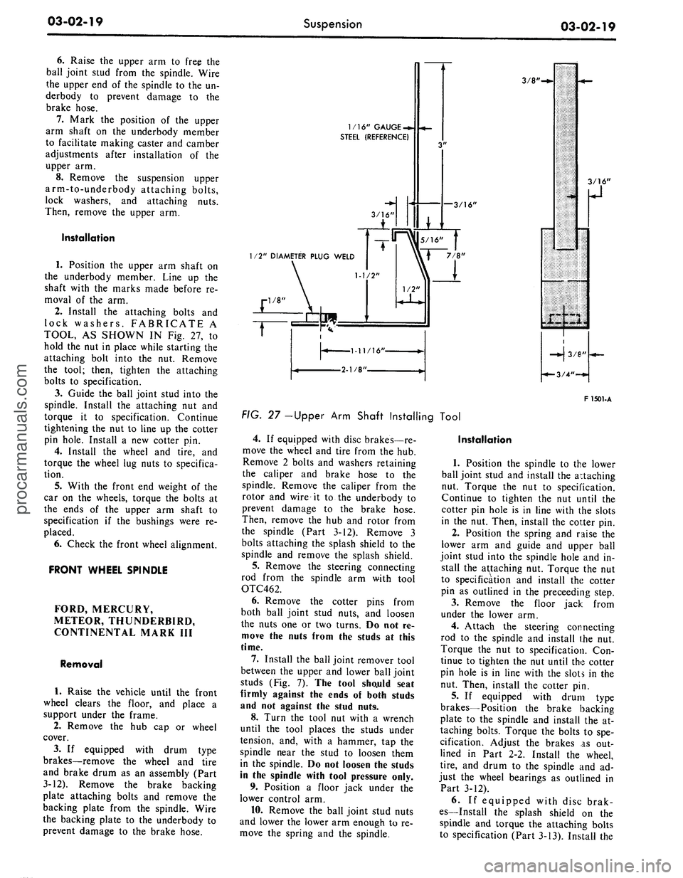
TOOL, AS SHOWN IN Fig. 27, to
hold the nut in place while starting the
attaching bolt into the nut. Remove
the tool; then, tighten the attaching
bolts to specification.
3.
Guide the ball joint stud into the
spindle. Install the attaching nut and
torque it to specification. Continue
tightening the nut to line up the cotter
pin hole. Install a new cotter pin.
4.
Install the wheel and tire, and
torque the wheel lug nuts to specifica-
tion.
5.
With the front end weight of the
car on the wheels, torque the bolts at
the ends of the upper arm shaft to
specification if the bushings were re-
placed.
6. Check the front wheel alignment.
FRONT WHEEL SPINDLE
FORD, MERCURY,
METEOR, THUNDERBIRD,
CONTINENTAL MARK III
Removal
1.
Raise the vehicle until the front
wheel clears the floor, and place a
support under the frame.
2.
Remove the hub cap or wheel
cover.
3.
If equipped with drum type
brakes—remove the wheel and tire
and brake drum as an assembly (Part
3-12). Remove the brake backing
plate attaching bolts and remove the
backing plate from the spindle. Wire
the backing plate to the underbody to
prevent damage to the brake hose.
1/16" GAUGE
-*.
STEEL (REFERENCE)
—3/16'
3/8'
1/2" DIAMETER PLUG WELD
F 1501-A
FIG. 27 -Upper Arm Shaft Installing Tool
4.
If equipped with disc brakes—re-
move the wheel and tire from the hub.
Remove 2 bolts and washers retaining
the caliper and brake hose to the
spindle. Remove the caliper from the
rotor and wire it to the underbody to
prevent damage to the brake hose.
Then, remove the hub and rotor from
the spindle (Part 3-12). Remove 3
bolts attaching the splash shield to the
spindle and remove the splash shield.
5.
Remove the steering connecting
rod from the spindle arm with tool
OTC462.
6. Remove the cotter pins from
both ball joint stud nuts, and loosen
the nuts one or two turns. Do not re-
move the nuts from the studs at this
time.
7.
Install the ball joint remover tool
between the upper and lower ball joint
studs (Fig. 7). The tool sho.uld seat
firmly against the ends of both studs
and not against the stud nuts.
8. Turn the tool nut with a wrench
until the tool places the studs under
tension, and, with a hammer, tap the
spindle near the stud to loosen them
in the spindle. Do not loosen the studs
in the spindle with tool pressure only.
9. Position a floor jack under the
lower control arm.
10.
Remove the ball joint stud nuts
and lower the lower arm enough to re-
move the spring and the spindle.
Installation
1.
Position the spindle to the lower
ball joint stud and install the attaching
nut. Torque the nut to specification.
Continue to tighten the nut until the
cotter pin hole is in line with the slots
in the nut. Then, install the cotter pin.
2.
Position the spring and raise the
lower arm and guide and upper ball
joint stud into the spindle hole and in-
stall the attaching nut. Torque the nut
to specification and install the cotter
pin as outlined in the preceeding step.
3.
Remove the floor jack from
under the lower arm.
4.
Attach the steering connecting
rod to the spindle and install the nut.
Torque the nut to specification. Con-
tinue to tighten the nut until the cotter
pin hole is in line with the slots in the
nut. Then, install the cotter pin.
5.
If equipped with drum type
brakes—Position the brake backing
plate to the spindle and install the at-
taching bolts. Torque the bolts to spe-
cification. Adjust the brakes as out-
lined in Part 2-2. Install the wheel,
tire,
and drum to the spindle and ad-
just the wheel bearings as outlined in
Part 3-12).
6. If equipped with disc brak-
es—Install the splash shield on the
spindle and torque the attaching bolts
to specification (Part 3-13). Install theprocarmanuals.com
Page 96 of 413
03-02-20
Suspension
03-02-20
hub and rotor on the spindle. Position
the caliper over the rotor and install
the attaching bolts. Torque the bolts
to specification (Part 3-13). Install the
wheel and tire on the hub and adjust
the wheel bearings as outlined in Part
3-12 .
7.
Install the hub cap or wheel
cover. Then, remove the support stand
and lower the vehicle.
8. Check caster, camber, and toe-in
(Part 3-1) and adjust as necessary.
COUGAR, FAIRLANE,
FALCON, MONTEGO,
MUSTANG
Drum Brakes
Removal
1.
Position a support between the
upper arm and frame as shown in
Figs.
8 and 9; then, raise the vehicle
and position safety stands.
2.
Remove the hub cap or wheel
cover.
3.
Remove the grease cap from the
hub;
then, remove the adjusting nut,
washer, and outer bearing cone and
roller assembly.
4.
Pull the wheel, hub, and drum
assembly off the wheel spindle.
5.
Remove the brake backing plate
from the spindle. Support the plate to
prevent damage to the brake hose.
6. Disconnect the spindle connect-
ing rod end from the spindle arm
using Tool 3290-C.
7.
Remove the cotter pins from
both ball joint stud nuts, and loosen
the nuts one or two turns. Do not re-
move the nuts from the studs at this
time.
8. Position the ball joint remover
tool between the upper and lower ball
joint studs (Fig. 10). The tool should
seat firmly against the ends of both
studs and not against the stud nuts.
9. Turn the tool with a wrench until
the tool places the studs under consid-
erable tension, and, with a hammer,
hit the spindle smartly near the studs
to break them loose in the spindle. Do
not loosen the studs in the spindle
with tool pressure alone.
10.
Remove the stud nuts and re-
move the spindle from both studs.
Installation
1.
Position the spindle on the lower
ball joint stud and install the stud nut
(Fig. 25).
2.
Raise the lower suspension arm
and guide the upper ball joint stud
into the spindle. Install the stud nut.
3.
Torque the upper stud nut and
then the lower stud nut to specifica-
tion. Continue to tighten both nuts
until the cotter pin holes and slots line
up.
Install new cotter pins.
4.
Connect the spindle connecting
rod end to the spindle arm.
5.
Install the brake backing plate
on the spindle, and torque the bolts to
specification.
6. Install the wntel and drum and
adjust the wheel bearing (Part 3-12).
7.
Remove the safety stands, and
lower the vehicle.
8. Remove the support from be-
tween the upper arm and frame.
9. Check and, if necessary, adjust
caster, camber, and toe-in.
Disc Brakes
Removal
1.
Remove the hub cap or wheel
cover, and remove the wheel and tire
from the hub.
2.
Remove two bolts attaching the
caliper to the spindle. Remove the cal-
iper from the rotor and wire it to the
underbody to prevent damage to the
brake hose.
3.
Remove the grease cap from the
hub,
then, remove the adjusting nut,
washer, and outer bearing cone and
roller assembly.
4.
Pull the hub and rotor assembly
off the wheel spindle.
5.
Remove the three caliper shield
attaching bolts and remove the shield.
6. Disconnect the spindle connect-
ing rod end from the spindle arm
using Tool-3290-C.
7.
Remove the cotter pins from
both ball joint stud nuts, and loosen
the nuts one or two turns. Do not re-
move the nuts from the studs at this
time.
8. Position the ball joint remover
tool between the upper and lower ball
joint studs (Fig. 10). The tool should
seat firmly against the ends of both
studs and not against the stud nuts.
9. Turn the tool with a wrench until
the tool places the studs under consid-
erable tension, and, with a hammer,
hit the spindle smartly near the studs
to break them loose in the spindle. Do
not loosen the studs in the spindle
with tool pressure alone.
10.
Position a floor jack under the
lower suspension arm.
11.
Remove the upper and lower
ball joint stud nuts; lower the jack
and remove the spindle.
Installation
1.
Position the spindle on the lower
ball joint stud and install the stud nut
(Fig. 25). Torque the nut to specifica-
tion and install the cotter pin.
2.
Raise the lower suspension arm,
and guide the upper ball joint stud
into the spindle. Install the stud nut.
3.
Torque the nut to specifications
and install the cotter pin. Then, re-
move the floor jack.
4.
Connect the spindle connecting
rod end to the spindle arm and install
the attaching nut. Torque the nut to
specification and install the cotter pin.
5.
Position the caliper splash shield
to the spindle and install the attaching
bolts and nuts. Torque the nuts and
bolts to specification.
6. Install the hub and rotor on the
spindle.
7.
Position the caliper to the rotor
and spindle and install the attaching
bolts.
Torque the bolts to specification
and install the safety wire.
8. Install the wheel and tire on the
hub and adjust the wheel bearing
(Part 3-12).
9. Install the hub cap or wheel
cover.
10.
Before driving the vehicle,
pump the brake pedal several times to
obtain normal brake lining-to-rotor
clearance and restore normal brake
pedal travel.
LINCOLN CONTINENTAL
Removal
1.
Raise the vehicle. Place a sup-
port under each side rail to the rear of
the lower arm in the lifting pad area.
2.
Remove the wheel and tire from
the hub.
3.
Remove 2 bolts and washers that
attach the caliper to the spindle. Re-
move the caliper from the rotor and
wire it to the underbody to prevent
damage to the brake hose.
4.
Remove the hub and rotor from
the spindle.
5.
Remove the splash shield and
gasket from the spindle.
6. Disconnect the spindle arm con-
necting rod from the spindle arm with
Tool 3290-C. See Fig. 23.
7.
Remove the cotter pins from
both ball joint stud nuts. Loosen the
nuts one to two turns.procarmanuals.com
Page 97 of 413
03-02-21
Suspension
03-02-21
8. Place a box wrench over the
lower end of the ball joint remover
tool, and position the tool as in Fig.
13.
The tool should seat firmly against
the ends of both studs, and not
against the stud nuts.
9. Turn the wrench until both studs
are under tension, and then, tap the
spindle with a hammer near the studs
to loosen them from the spindle. Do
not loosen
the
studs with tool pressure
alone.
10.
Place a jack under the outer
end of the lower arm, and raise the
arm several inches. Remove both ball
stud nuts, and remove t^e spindle.
Installation
1.
Position the new spindle onto the
upper and lower ball joint studs, in-
stall the stud nuts and tighten the nuts
to specifications. Continue to tighten
both nuts until the cotter pin holes
line up with the slots, then install new
cotter pines.
2.
Connect the spindle connecting
rod to the spindle arm. Install the re-
taining nut and tighten the nut to
specification. Continue to tighten the
nut until the cotter pin hole lines up
with the slot, then install a new cotter
pin.
3.
Install the gasket and splash
shield on the spindle. Tighten the at-
taching bolts to specifications.
4.
Install the hub and rotor on the
spindle.
5.
Install the caliper to the spindle
and tighten the attaching bolts to spe-
cifications. Check for the correct flex-
ible hose routing (Part 2-2).
6. Install the wheel and tire and ad-
just the wheel bearings (Part 3-12).
7.
Lubricate the steering stop on
the lower arm and the mating flat on
the spindle with the specified lubri-
cant.
8. Remove the safety stands, lower
the car and check camber, caster and
toe-in.
FRONT SHOCK ABSORBER
REPLACEMENT
FORD, MERCURY,
METEOR, THUNDERBIRD,
CONTINENTAL MARK III
1.
Remove the nut, washer, and
bushing from the shock absorber
upper end.
2.
Raise the vehicle on a hoist and
install safety stands.
3.
Remove 2 bolts attaching the
shock absorber to the lower arm and
remove the shock absorber.
4.
Place a washer and bushing on
the shock absorber top stud and posi-
tion the shock absorber inside the
front spring. Install the 2 lower at-
taching bolts and torque them to spe-
cifications.
5.
Remove the safety stands and
lower the vehicle.
6. Place a bushing and washer on
the shock absorber top stud and in-
stall the attaching nut. Torque it to
specification.
COUGAR, FAIRLANE,
FALCON, MONTEGO,
MUSTANG
Removal
1. Raise the hood and remove 3
shock absorber upper mounting
bracket-to-spring tower attaching
nuts.
2.
Raise the front of the vehicle and
place safety stands under the lower
arms.
3.
Remove 2 shock absorber lower
attaching nuts and washers.
4.
Lift the shock absorber and
upper bracket from the spring tower
(Fig. 26) and remove the bracket from
the shock absorber.
Installation
1. Install the upper mounting
bracket on the shock absorber and
torque to specification.
2.
Position the shock absorber and
upper mounting bracket in the spring
tower, making sure the shock absor-
ber lower studs are in the pivot plate
holes.
3.
Install the 2 washers and attach-
ing nuts on the shock absorber lower
studs and torque to specification.
4.
Install the 3 shock absorber
upper mounting bracket-to-spring
tower attaching nuts and torque to
specification. Then, remove the safety
stands and lower the vehicle.
LINCOLN CONTINENTAL
Removal
1.
Remove the stud nut at the
upper eye of the shock absorber. Re-
move the upper eye stud bracket to
crossmember attaching bolt and re-
move the stud bracket. Refer to Fig.
22.
2.
Remove the bolts which attach
the shock absorber to the suspension
lower arm. Lower, and remove the
shock absorber.
3.
Examine the shock absorber unit
and rubber bushings. Replace parts
that are defective, deteriorated, or
worn.
Installation
1. Fully extend the shock absorber
and position it inside the coil spring.
Connect the lower end of the shock
absorber to the suspension lower arm.
Torque the attaching nuts to specifica-
tion.
2.
Insert the upper bracket stud
through the bushing in the shock ab-
sorber upper eye. Install the stud
bracket to crossmember attaching
bolt. Do not tighten the bolt: at this
time.
3.
Install the upper eye bracket
stud nut. Torque the nut to specifica-
tion.
4.
Torque the stud bracket- to-
crossmember attaching bolt to specifi-
cation.
The
shock absorber upper
eye
stud
nut
must
be
tightened
to com-
press
the
rubber bushing before
the
stud bracket
is
bolted
to the
crossmember;
otherwise,
the
upper
at-
tachment could
be
loose
and
noisy.
REAR SHOCK ABSORBER
REPLACEMENT
FORD, MERCURY,
METEOR, THUNDERBIRD,
CONTINENTAL MARK 1(11
1.
Raise the vehicle on a hoist.
2.
Remove the shock absorber at-
taching nut, washer and insulator
from the upper stud at the upper side
of the spring upper seat. Compress the
shock absorber to clear the hole in the
spring seat, and remove the inner in-
sulator and washer from the upper at-
taching stud.
3.
Remove the self-locking attach-
ing nut, and disconnect the shock ab-
sorber lower stud from the mounting
bracket on the rear axle housing (Fig.
4).
4.
Expel all air by performing step
3 On Vehicle Tests in Part 3-1.
5.
Place the inner washer and insu-
lator on the upper attaching stud, and
position the shock absorber so that
the upper attaching stud enters the
hole in the spring upper seat. While
holding the shock absorber in this po-
sition, install the outer insulator andprocarmanuals.com
Page 98 of 413
03-02-22
Suspension
03-02-22
washer and the nut on the upper stud
from the upper side of the spring
upper seat. Torque the nut to specifi-
cations.
6. Extend the shock absorber and
locate the lower stud in the hole in
mounting bracket on the rear axle
housing. Install a new self-locking at-
taching nut and torque to specifica-
tion.
MUSTANG AND COUGAR
Removal
1.
Disconnect the shock absorber
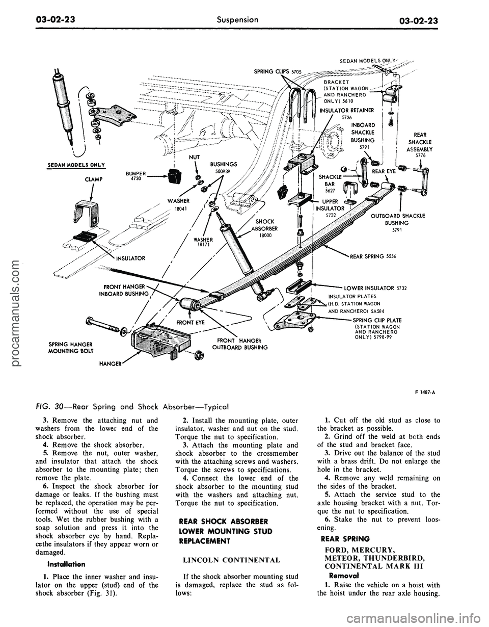
from the spring clip plate (Fig. 30).
2.
Remove the shock absorber ac-
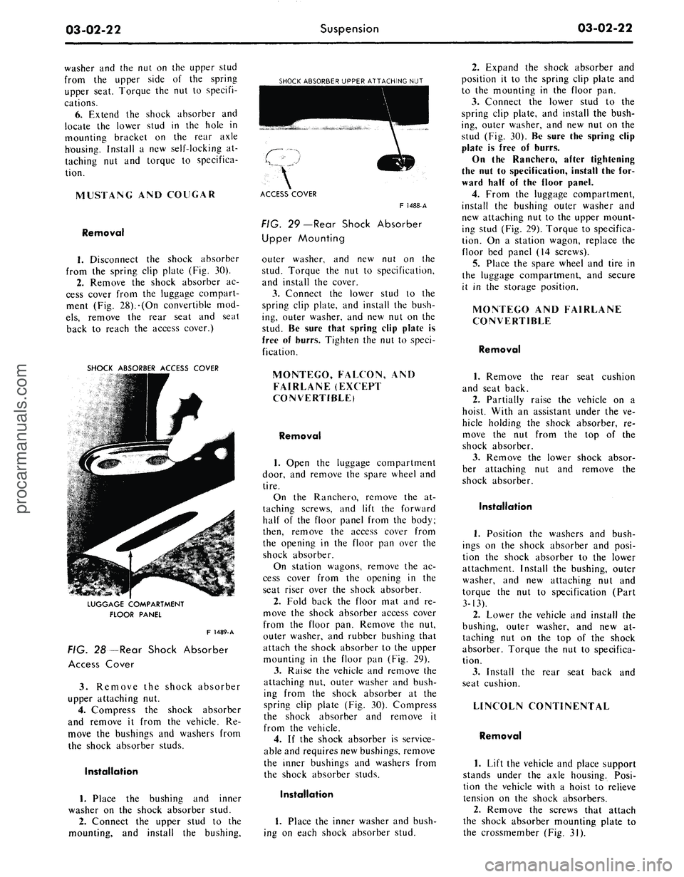
cess cover from the luggage compart-
ment (Fig. 28).-(On convertible mod-
els,
remove the rear seat and seat
back to reach the access cover.)
SHOCK ABSORBER ACCESS COVER
SHOCK ABSORBER UPPER ATTACHING NUT
LUGGAGE COMPARTMENT
FLOOR PANEL
F 1489-A
FIG. 28—Rear Shock Absorber
Access Cover
3.
Remove the shock absorber
upper attaching nut.
4.
Compress the shock absorber
and remove it from the vehicle. Re-
move the bushings and washers from
the shock absorber studs.
Installation
1.
Place the bushing and inner
washer on the shock absorber stud.
2.
Connect the upper stud to the
mounting, and install the bushing,
ACCESS COVER
F 1488-A
FIG. 29—Rear Shock Absorber
Upper Mounting
outer washer, and new nut on the
stud. Torque the nut to specification,
and install the cover.
3.
Connect the lower stud to the
spring clip plate, and install the bush-
ing, outer washer, and new nut on the
stud. Be sure that spring clip plate is
free of burrs. Tighten the nut to speci-
fication.
MONTEGO, FALCON, AND
FAIRLANE (EXCEPT
CONVERTIBLE)
Removal
1.
Open the luggage compartment
door, and remove the spare wheel and
tire.
On the Ranchero, remove the at-
taching screws, and lift the forward
half of the floor panel from the body;
then, remove the access cover from
the opening in the floor pan over the
shock absorber.
On station wagons, remove the ac-
cess cover from the opening in the
seat riser over the shock absorber.
2.
Fold back the floor mat and re-
move the shock absorber access cover
from the floor pan. Remove the nut,
outer washer, and rubber bushing that
attach the shock absorber to the upper
mounting in the floor pan (Fig. 29).
3.
Raise the vehicle and remove the
attaching nut, outer washer and bush-
ing from the shock absorber at the
spring clip plate (Fig. 30). Compress
the shock absorber and remove it
from the vehicle.
4.
If the shock absorber is service-
able and requires new bushings, remove
the inner bushings and washers from
the shock absorber studs.
Installation
1.
Place the inner washer and bush-
ing on each shock absorber stud.
2.
Expand the shock absorber and
position it to the spring clip plate and
to the mounting in the floor pan.
3.
Connect the lower stud to the
spring clip plate, and install the bush-
ing, outer washer, and new nut on the
stud (Fig. 30). Be sure the spring clip
plate is free of burrs.
On the Ranchero, after tightening
the nut to specification, install the for-
ward half of the floor panel.
4.
From the luggage compartment,
install the bushing outer washer and
new attaching nut to the upper mount-
ing stud (Fig. 29). Torque to specifica-
tion. On a station wagon, replace the
floor bed panel (14 screws).
5.
Place the spare wheel and tire in
the luggage compartment, and secure
it in the storage position.
MONTEGO AND FAIRLANE
CONVERTIBLE
Removal
1.
Remove the rear seat cushion
and seat back.
2.
Partially raise the vehicle on a
hoist. With an assistant under the ve-
hicle holding the shock absorber, re-
move the nut from the top of the
shock absorber.
3.
Remove the lower shock absor-
ber attaching nut and remove the
shock absorber.
Installation
1.
Position the washers and bush-
ings on the shock absorber and posi-
tion the shock absorber to the lower
attachment. Install the bushing, outer
washer, and new attaching nut and
torque the nut to specification (Part
3-13).
2.
Lower the vehicle and install the
bushing, outer washer, and new at-
taching nut on the top of the shock
absorber. Torque the nut to specifica-
tion.
3.
Install the rear seat back and
seat cushion.
LINCOLN CONTINENTAL
Removal
1.
Lift the vehicle and place support
stands under the axle housing. Posi-
tion the vehicle with a hoist to relieve
tension on the shock absorbers.
2.
Remove the screws that attach
the shock absorber mounting plate to
the crossmember (Fig. 31).procarmanuals.com
Page 99 of 413
03-02-23
Suspension
03-02-23
SEDAN MODELS ONLY-
SPRING CLIPS
5705
,^-::^^^^SSSS^
^CS^.-''' .--'""-.'.'""'"* D D
A
f~
V
C
T
BRACKET
(STATION WAGON-
AND RANCHERO
ONLY) 5610
INSULATOR RETAINER
5736
INBOARD
SHACKLE
BUSHING
5791
... ».IA-
vae.
FRONT HANGER
INBOARD BUSHING
FRONT HANGER
OUTBOARD BUSHING
REAR
SHACKLE
ASSEMBLY
5776
OUTBOARD SHACKLE
BUSHING
5791
LOWER INSULATOR 5732
INSULATOR PLATES
(H.D.
STATION WAGON
AND RANCHERO) 5A584
SPRING CLIP PLATE
(STATION WAGON
AND RANCHERO
ONLY) 5798-99
SPRING HANGER
MOUNTING BOLT
HANGER
FIG. 30—Rear Spring and Shock Absorber—Typical
3.
Remove the attaching nut and
washers from the lower end of the
shock absorber.
4.
Remove the shock absorber.
5.
Remove the nut, outer washer,
and insulator that attach the shock
absorber to the mounting plate; then
remove the plate.
6. Inspect the shock absorber for
damage or leaks. If the bushing must
be replaced, the operation may be per-
formed without the use of special
tools.
Wet the rubber bushing with a
soap solution and press it into the
shock absorber eye by hand. Repla-
cethe insulators if they appear worn or
damaged.
Installation
1.
Place the inner washer and insu-
lator on the upper (stud) end of the
shock absorber (Fig. 31).
2.
Install the mounting plate, outer
insulator, washer and nut on the stud.
Torque the nut to specification.
3.
Attach the mounting plate and
shock absorber to the crossmember
with the attaching screws and washers.
Torque the screws to specifications.
4.
Connect the lower end of the
shock absorber to the mounting stud
with the washers and attaching nut.
Torque the nut to specification.
REAR SHOCK ABSORBER
LOWER MOUNTING STUD
REPLACEMENT
LINCOLN CONTINENTAL
If the shock absorber mounting stud
is damaged, replace the stud as fol-
lows:
F 1487-A
1.
Cut off the old stud as close to
the bracket as possible.
2.
Grind off the weld at both ends
of the stud and bracket face.
3.
Drive out the balance of the stud
with a brass drift. Do not enlarge the
hole in the bracket.
4.
Remove any weld remaining on
the sides of the bracket.
5.
Attach the service stud to the
axle housing bracket with a nut. Tor-
que the nut to specification.
6. Stake the nut to prevent loos-
ening.
REAR SPRING
FORD, MERCURY,
METEOR, THUNDERBIRD,
CONTINENTAL MARK III
Removal
1.
Raise the vehicle on a hoist with
the hoist under the rear axle housing.procarmanuals.com
Page 100 of 413
03-02-24
Suspension
03-02-24
LOCK NUT
INSULATOR
NG
NUT
MOUNTING STUD
WASHER
LOCK WASHER
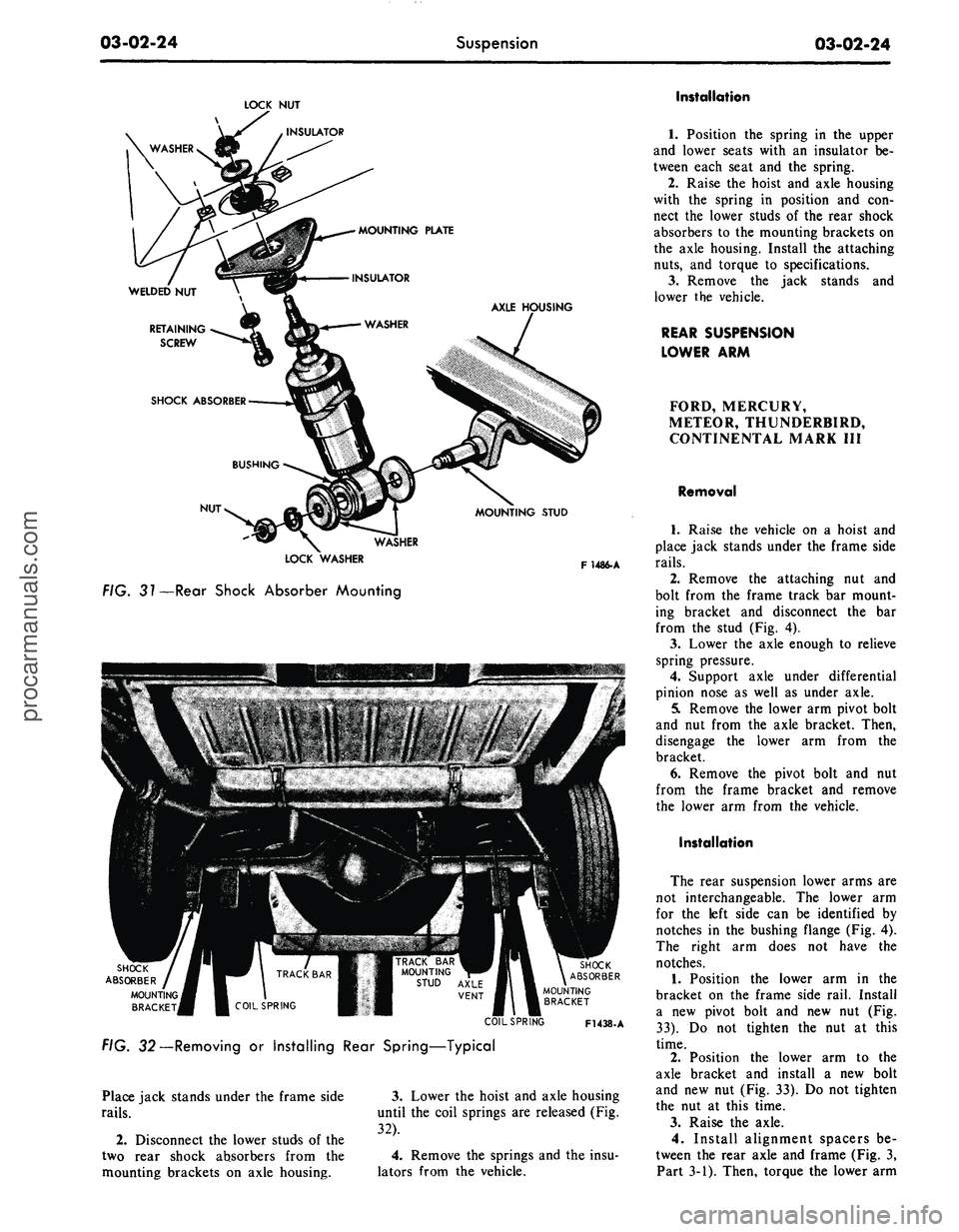
FIG. 31—Rear Shock Absorber Mounting
F1486-A
TRACK BAR
MOUNTING
STUD AXLE
VENT
SHOCK
ABSORBER
MOUNTING
BRACKET
SHOCK
ABSORBER
MOUNTING
BRACKET
V-V.
FIG. 32—Removing or Installing Rear Spring—Typical
COIL SPRING
F1438-A
Place jack stands under the frame side
rails.
2.
Disconnect the lower studs of the
two rear shock absorbers from the
mounting brackets on axle housing.
3.
Lower the hoist and axle housing
until the coil springs are released (Fig.
32).
4.
Remove the springs and the insu-
lators from the vehicle.
Installation
1.
Position the spring in the upper
and lower seats with an insulator be-
tween each seat and the spring.
2.
Raise the hoist and axle housing
with the spring in position and con-
nect the lower studs of the rear shock
absorbers to the mounting brackets on
the axle housing. Install the attaching
nuts,
and torque to specifications.
3.
Remove the jack stands and
lower the vehicle.
REAR SUSPENSION
LOWER ARM
FORD, MERCURY,
METEOR, THUNDERBIRD,
CONTINENTAL MARK III
Removal
1.
Raise the vehicle on a hoist and
place jack stands under the frame side
rails.
2.
Remove the attaching nut and
bolt from the frame track bar mount-
ing bracket and disconnect the bar
from the stud (Fig. 4).
3.
Lower the axle enough to relieve
spring pressure.
4.
Support axle under differential
pinion nose as well as under axle.
5.
Remove the lower arm pivot bolt
and nut from the axle bracket. Then,
disengage the lower arm from the
bracket.
6. Remove the pivot bolt and nut
from the frame bracket and remove
the lower arm from the vehicle.
Installation
The rear suspension lower arms are
not interchangeable. The lower arm
for the left side can be identified by
notches in the bushing flange (Fig. 4).
The right arm does not have the
notches.
1.
Position the lower arm in the
bracket on the frame side rail. Install
a new pivot bolt and new nut (Fig.
33).
Do not tighten the nut at this
time.
2.
Position the lower arm to the
axle bracket and install a new bolt
and new nut (Fig. 33). Do not tighten
the nut at this time.
3.
Raise the axle.
4.
Install alignment spacers be-
tween the rear axle and frame (Fig. 3,
Part 3-1). Then, torque the lower armprocarmanuals.com