ignition HONDA INTEGRA 1998 4.G Repair Manual
[x] Cancel search | Manufacturer: HONDA, Model Year: 1998, Model line: INTEGRA, Model: HONDA INTEGRA 1998 4.GPages: 1681, PDF Size: 54.22 MB
Page 331 of 1681
F
I
Fuel Supply
PGM-Fl Main
System
Relay (cont'd)
\
lb
i
(From page 11 125)
- Reprir open or short in thewire between the PGM-FI mainrelay and the No. 31 STARTERSIGNAL {7.5 A} tuse.- RoDlace the No. 31 STARTERSIGNAL {7.5 A) fuse in theunder-dash luse/relav box,
Check for an open in the wire
{FLR line}:1. Turn the ignation switch OFF.2. Disconnect the ECM connector A (32P).
3. Check for continuity betweenthe PGM-FI main relay 7P con-nector terminal No. 1 and ECMconnector terminal A16-
Repair open in the wire betweenthe ECM (A161 and the PGM-FImein relay,ls there continuity?
Check for an open in the wires{lGPl, lGP2lines}:1. Reconnect the ECM connectorA (32P).
2. Reconnect the PGM-Fl mainrelay 7P connector.3. Turn the ignition switch ON {ll).4. Measure vo ltage betweenECM connector terminals A10and A11, and between A10and 424.
- Repaar open in lhe wir€ bet-ween the ECM 1A11, A24l andthe PGM-FI main relay.- Repldce the PGM-FI main relay.
ls there battery voltage?
Substitute a known-good ECMand recheck. It prescribed vohageis now available. roplace lhe o.ig-inalECM.
ls there 1.0 V or less?
Check the PGM-Fl main relaylsee page 11-124).
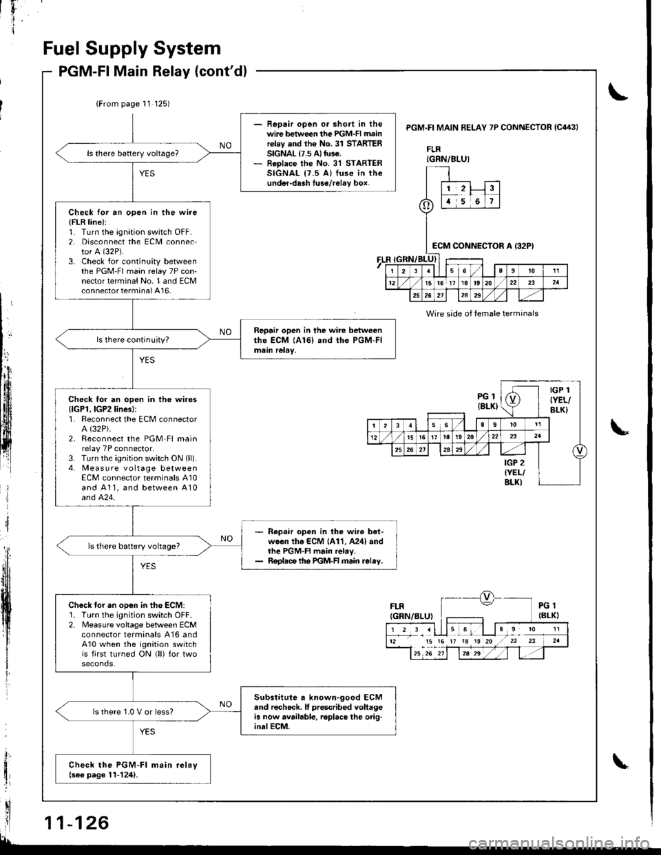
PGM.FI MAIN BELAY 7P CONNECTOR IC443I
FLR
FLR
Wire side of temale terminals
Check tor en open in the ECM:1. Turn the ignition switch OFF.2. Measure voltage betlveen ECMconnector termanals A16 andA10 when the ignition switchis first turned ON (ll) for two
IGRN/BLU}
o
1,2!t5i6
:cM CONNEi)TOR A I32P)
I23sl6a9to11
1215lor 17 18t920/22232a
25262l12329
PGl(8LKI
IGP 1
{YEL/BLK}
(
t356I
t5161t la192022
25a
IGP 2{YEL/BLKI
12 15 15 17 18 19 20 .r 22 23
Page 340 of 1681
Troublsshooting
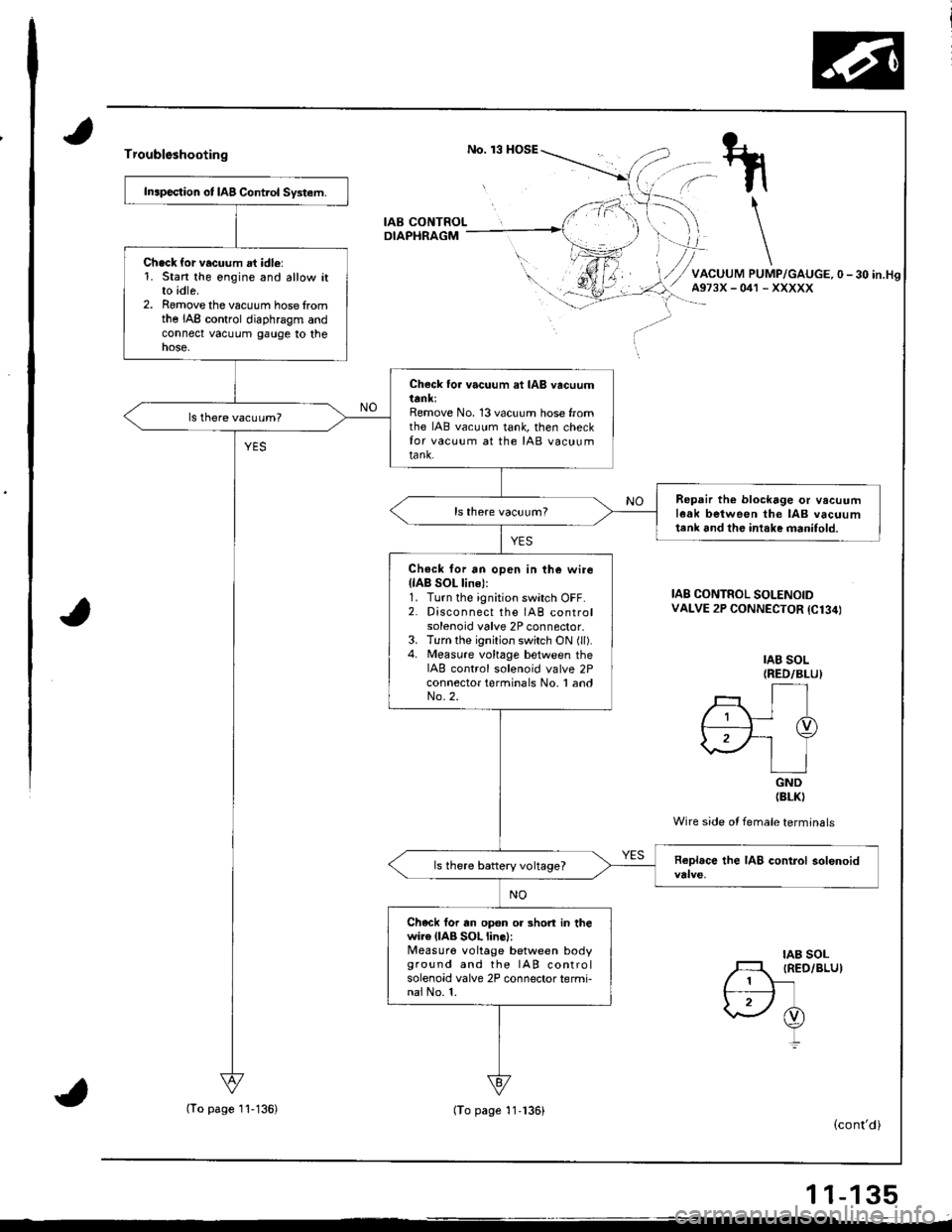
IAB CONTROLDIAPHRAGM
Inapection ot IAB Control System.
Chack {or vacuum at idle:1. Stan the engine and allow itto idle.2. Romove the vacuum hose fromthe IAB control diaphragm andconnect vacuum gauge to thenose,
Check to. vacuum at IAB vacuumttnl;Remove No. 13 vacuum hose fromthe IAB vacuum tank, then checkfor vacuum at the IAB vacuumtank.
Repair th€ blockage or vacuuml6ak between the IAB vacuumtenk 6nd the intake manifold.
Check for an open in the wirellAB SOL line):1. Turn the ignition switch OFF.2. Disconnect the IAB controlsolenoid valve 2P connector.3. Turn the ignition switch ON (ll).4. Measure vohage between theIAB control solenoid valve 2Pconnector terminals No, 1 andNo.2.
ls there battery voltage?
Chack for rn op€n or 3hort in thewire (lAB SOL line):Measuro voltage between bodyground and the IAB controlsolenoid valve 2P connector termi-nai No. 1.
IAB SOL(RED/BLUI
rt./; Ir I-TD,2F-' Y\.\/ | ]IGND(BLKI
Wire side ot female terminals
IAB CONTROL SOLENOIDVALVE 2P CONNECTOR {C134)
IAB SOLIRED/BLU)
(cont'd)
11-135
(To page I'l-136)(To page 11.136)
Page 341 of 1681
I
lntake
lntake
Air System
Air Bypass (lABl ControlSystem tB18C1 enginel (cont'd)
(From page 11i135)(From page 11 135)
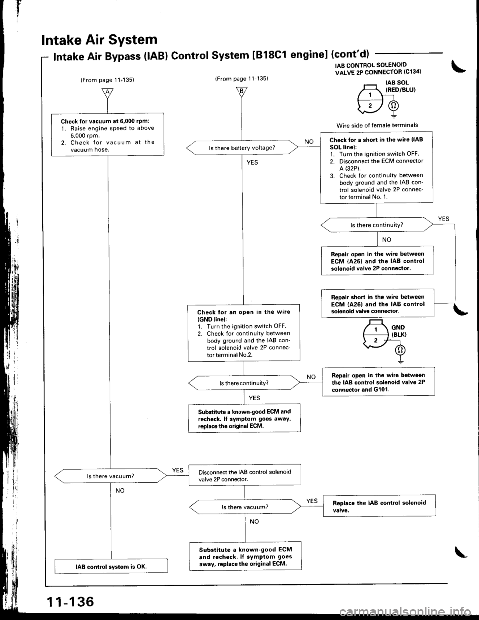
IAB CONTROL SOLENOID
VALVE 2P CONNECTOR (C13ir)
'._r taB sol-H, IRED/ALUI// 1 \-'lf---:----l /A\
\2Y
Wire side o{ female terminals
\
.t
Check {or vacuum at 6,000 rpm:
1, Raise engane speed to above
6,000 rpm.2. Check for vacuum at the
vacuum hose,
Disconnect the IAB control solenoidvalve 2P connector.ls there vacuum?
Substitute a known-good ECM
and recheck. lf symptom goes
away, replace the original ECM.IAB control svstom is OK.
Check lor a shon in the wire (lAB
SOL line):1. Turn the ignition switch OFF.2. Disconnect the ECM connector
A (32P).
3. Check for continuity betweenbody ground and the IAB con'
trol solenoid valve 2P connec-
torterminalNo. 1.
ls there battery voltage?
Repair open in the wire betwaonECM lA26) and the IAB controlsolenoid valve 2P connectoa.
Check tor an open in the wiro
{GND line)r1. Turn the ignition switch OFF.2. Check for continuity betweenbody ground and the IAB con-
trol solenoid valve 2P connector terminal No.2.
Repair open in the wire betweenthe IAB control solenoid valve 2Pconnector and G101.
Subdhnte a known-good ECM andrecheck. ll symptom goes away,r€place the original ECM.
\
Page 347 of 1681
lT
Emission Control System
YES
{To page 11-143}
Fu€l Tank Pressure Sensor
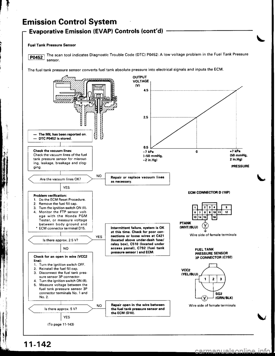
The scan tool indicates Diagnostic Trouble Code (DTC) P0452: A low voltage problem in the Fuel Tank Pressure
sensor.
The fuel tank pressure sensor converts tuel tank absolute pressure into electrical signals and inputs the ECM.
Evaporative Emission (EVAP) Controls (cont'dl
OUTPUTVOLTAGE(vl
4.5
0.5-7 kPel-50 mmHg,-2 in.Hgl
+7 lPe
l5o mmHg,2 in.Hgl
PRESSURE
\*
Eclrl CONNECToR o {lEPl
PTANK(wltT/BLul
vcc2IYEL/BLU}
Wire side of lemale terminals
FUEL TANKPRESSURE SENSOR
3P CONNECTOR (C792)
The MIL ha3 beon roportod on.OTC F0452 i3 storad.
Chock the vscuum lines:Check the vacuum lines otthe fueltank pressure sensor for misrout-ing, leakage, breakage and clog-ging.
Are the vacuum lines OK?
Problgm verilication:1. Do the ECM Reset Procedure.2. Remove the fuel fill cap.3. Turn the ignition switch ON lll).4. Monitor the FTP sensor volt-age with the Honda PGMTester, or measure voltagebotween body ground and' ECM connector terminal D15.Int6rmittent tailure, 3ystem i3 OKat thb tirn6. Chock lor poor con-n.clions or loo3e wire3 ot C421{locltod rbovo under-d!.h fuso/r.lay boxl, C510 lloc.ted undo.rcc.rs panoll, C?92 Ituel trnko.6sura i€nior I lnd ECM.
ls there approx.2.5 V?
Check to. an opon in wi.a {VCC2line):1. Turn the ignition switch OFF.2. Reinstall the fuel fill cap.3. Disconnect the luel tank pres'su re sensor 3P connector.4. Turnthe ignition switch ON (ll).
5. Measure voltage between thetuel tank pressure sensor 3Pconnector terminals No, 1 andNo.2.
R.pai. opcn in thg wir6 bdtwoonthc fual tank pro$ure 3enlor andtho EcM lDlo).ls there approx. 5 V?
11-142
Wire side oI temale terminals
Page 348 of 1681
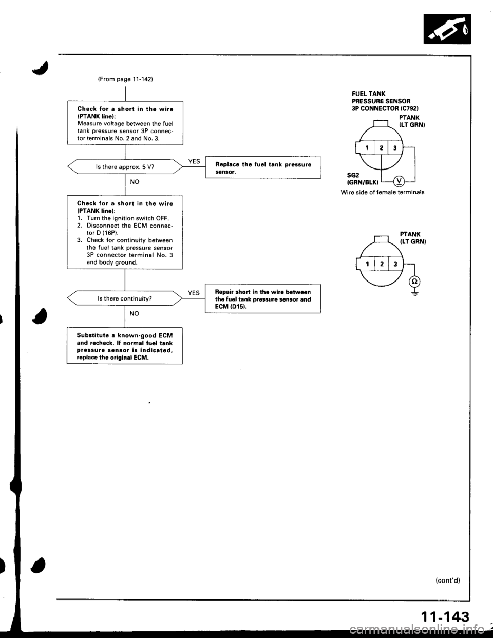
{From page 11-142i
Chock lor a short in tho wi.oIPTANK linel:Measure voltage between the fueltank pressure sensor 3P connec-tor terminals No. 2 and No. 3.
ls there approx. 5 V?
Chock for.3hort in th6 wi.e(PTANK lincl:1. Turn the ignition switch OFF.2. Disconnect the ECM connec,tor D (16P).
3. Check lor continuity betweenthe {uel tank pr€sslrre sensor3P connector terfiinal No. 3and body ground.
Ropri. 3hon in tho wira betwaGnthe fuel t.nk prosaura san3or andECM tD15t.
Substituta s known-good ECM.nd recheck. It normel fuel tenkpressure son30r is indicatod,raplacg tho o.iginal ECM.
FUEL TANKPRESSURC SENSOR3P CONNECTOR lc792l
PTANKILT GRN}
sG2IGRN/BLKI
Wire sido of temale terminals
(cont'd)
11-143
Page 349 of 1681
rI
Emission Control System
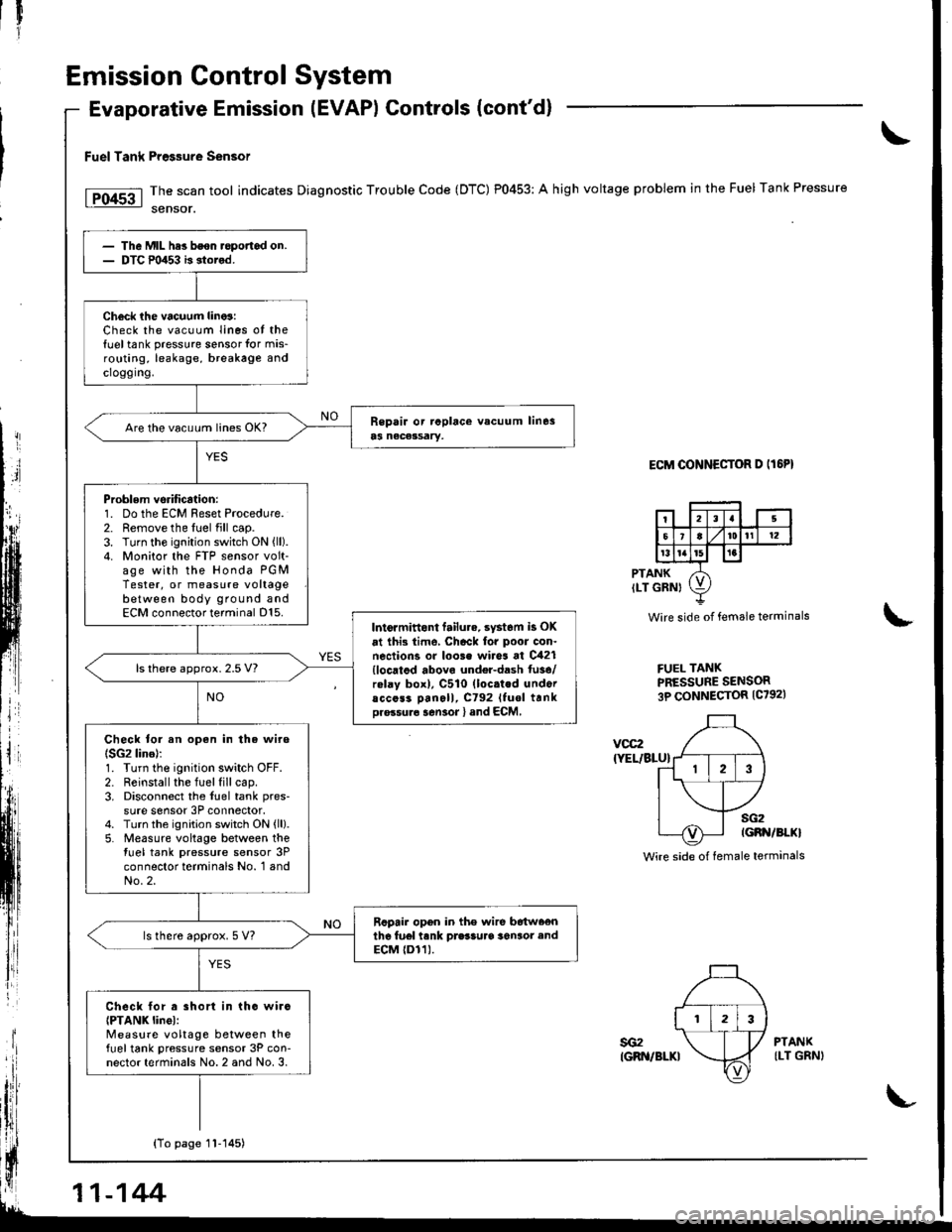
Evaporative Emission (EVAPI Controls (cont'd)
Fuel Tank Pre$ure sensor
The scan tool indicates Diagnostic Trouble Code (DTC) P0453: A high voltage problem in the Fuel Tank Pressure
sensor.
ECM OONNECTOR D IT6PI
PTANKILT GRNI
Wire side of female terminals
FUEL TANKPRESSURE SENSOR3P CONNECTOR {C7921
\
voc2
{YEL/BLU}
sG2IGBN/BI.KI
Wire side of female terminals
The Mll- hes bson.opofiad on.DTC m453 b stored.
Check ihe vacuum lino3:Check the vacuum Iines ot the{uel tank pressure sensor for mis-routing, leakage, breakage andcroggrng.
Are the vacu!m lin€s OK?
Problem vsrification:1. Do the ECM Reset Procedure.2. Remove the fuel fill cap.3. Turn the ignition switch ON {ll).4. Monitor the FTP sensor volt-age with the Honda PGMTester, or measure voltagebetween body ground andECM connector terminal D15.Intormittont failu.e. syst6m is OK
at ihi3 time, Chack for poor con.nections or loo3e wires at C421{locatod abovo undel-dash fu3e/rolay box), C510 (loc.ted undoracc6s3 Dan6ll, C792 Ituol trnkDro.su.6 sen3or l and ECM,
ls there approx. 2.5 V?
Check tor an open in the wire(SG2 lino):1. Turn the ignition switch OFF.2. Reinstall the fuel fill cap.3. Disconnect the fuel tank pres-
sure sensor 3P connector.4. Turn the ignition switch ON {ll}.5. Measure voltage between thetuel tank pressure sensor 3Pconnector terminals No. 1 andNo.2.
Rcpair opon in the wire b6tw66nthe fu6l tank prasSuaa 36n3or endECM {Dr1).ls there approx. 5 V?
Check lor a short in tho wirc{PTANK linel:Measure voltage between thefueltank pressure sensor 3P con-nector terminals No. 2 and No. 3.
YES
sG2IGRN/BLKI
PTANKILT GRNI
{To page 1l-145)
11-144
Page 351 of 1681
Il
1l
Iil
Emission Control SYstem
EVAPrHREEWAYVALVE
tFi4s6l
fPf 45? I
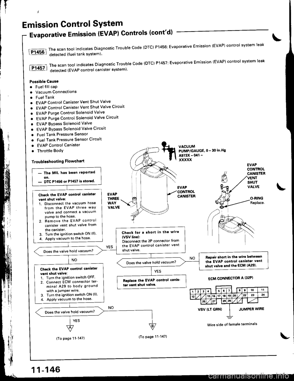
Evaporative Emission {EVAP) Controls (cont'd)
Possible Csuse
. Fuel fill cap
. Vacuum Connections
. FuelTank
. EVAP Control Canister Vent Shut Valve
. EVAP Control Canister Vent Shut Valve Circuit
. EVAP Purge control Solenoid Valve
. EVAP Purge Control Solenoid Valve Circuit
. EVAP Bypass Solenoid Valve
. EVAP Bypass Solenoid Valve Circuit
o FuelTank Pressure Sensor
. Fuel Tank Pressure Sensor Circuit
. EVAP Control Canister
. Throftle Body
Troubloshooling Flowchart
The scan tool indicates Diagnostic Trouble Code {DTC) P1456: Evaporative Emission (EVAP) control system leak
detected (fuel tank system).
ThescantoolindicatesDiagnosticTroubleCode(DTC)P't457:EvaporativeEmission(EVAP)controlsystemleak
detected (EVAP control canister system)'
VACUUMPUMP/GAUGE,0 - 30 in.Bs
A973X - 041 -
xxxxx
EVAP
CANISTER
EVAPCONTROLCANISTERVENTSHUTVALVE
O-RINGReplace.
ECM CONNECTOR A I32P)
(To page 11-147)
- Tho MIL ha3 bcan t6po.tod
on.- DTC P1,t56 or P1457 i! 3toLd.
Chcck the EVAP contiol canittc.
vont shut valva:1. Disconnect the vacuum hose
Irom the EVAP three way
valve and conned a vacuumpump to the hose
2. Remove the EVAP control
canister vent shut valve {rom
the canister.3. Turn the ignition switch ON lll)
4. Apply vacuum to the hose
Chack tor a lhort in tho wire
lVSv linol:Disconnect the 2P conn€ctor from
the EVAP control canister vent
Does the valve hold vacuum?
Rcp.i. ahoft in thc wir. bctw.cn
th6 EVAP conlrol caniator v.nt
3hut valve snd the ECM lA29).Does the valve hold vacuum?
Check tha EVAP coitlol canittcr
vent 3hut valvo:1. Turn the ignition switch OFF
2. Connect ECM connoctor ter'
minal A29 to bodY ground
whh a iumPer wlre
3. Turn the ignition switch ON (ll).
4. Apply vacuum to the hose.
Baplaca tha EVAP control c!ni!'
td vant 3hul Yalvc.
Does the valve hold vacuum?
38t0tl
1215[6'tat92Au232a
2t27a22
VSV {LT GRN) I JUMPER WIRE
Wire side o{ {emale terminals
11-146
{To page 11'147)
Page 352 of 1681
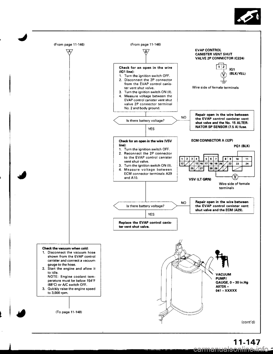
(From psge 11-146)
(To page 11-148)
Chack tho vldlum wh.n cold:'1. Disconnscl the vacuum hoseshown from the EVAP controlcanrster ano connect a vacuumgauge to the hose.2. Start the engine and aliow itto idls.NOTE: Engine coolant tem-porat{rre must be below 154"F{68'C} or A/C switch OFF.3. Ouickly raise the engine speedto 3,000 rpm.
lFrom page 11-146)
Check lor an opon in lhe wir€(lG1 lin6l:1. Turn the ignition switch OFF.2. Disconnect the 2P connectorlrom the EVAP control canis-ter vent shut valve.3. Turn the ignition switch ON (ll).
4. Measure voltage between theEVAP control canister vent shutvalve 2P connector terminalNo. 2 and body ground.
Ropair open in the wir6 betweonthe EVAP control canistor v6ntshut valve end the No. 15 ALTER-NATOR SP SENSOR 17.5 Al tu!e.
Ch€ck tor rn op€n in iho wire IVSVline):1. Turn tho ignition switch OFF.2. Reconnect the 2P connectorto the EVAP control canistervent shut valve,3. Turn the ignition switch ON (ll).
4, Measure vo ltage betweenECN/l connector terminals A29and A10.
Repair open in the wire beiwa€nthe EVAP cont.ol cenister ventshut valve and the EcM {4291.ls there baftery vohage?
ReDlacs tho EVAP cont.ol canis"ter vent shut valve.
EVAP CONTROLCANISTER VENT SHUIVALVE 2P CONNECTOR IC224)
.FJ.\1121-T rcl
(D (BLK/YEL)
I
Wire side ot female terminals
ECM CONNECIOR A {32P}
VSV ILT GRNI
Wire side of femaletermtnars
VACUUMPUMP/GAUGE,0 - 30 in.H94973X -
0a1 - xxxxx
(cont'd )
11-147
PG1 (BLKI
rl
4lq-r'rri l12t5t6t?l8r@llzzlzslul
25212a2
__l
Page 353 of 1681
Emission Control System
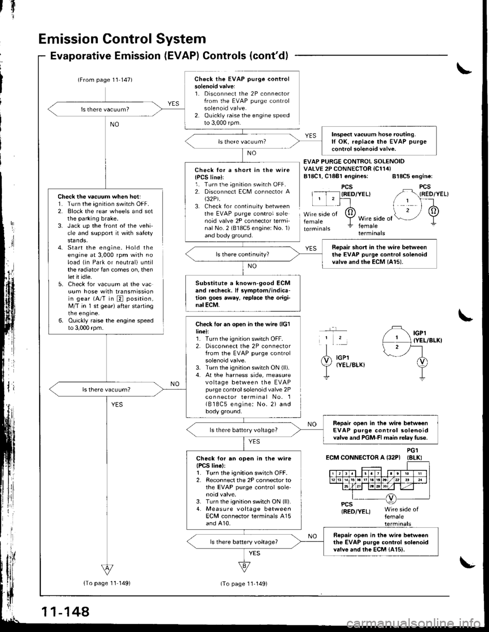
Check the vacuum when hot:1. Turn the ignition switch OFF.2. Block the rear wheels and setthe parking brake.3. Jack up the front of the vehi-cle and support it with safetystands.4- Start the engine. Hold theengine at 3,000 rpm with noload (in Park or neutral) untilthe radiator fan comes on, thenlet it idle.5. Check for vacuum at the vacuum hose with transmissionin gear (A/T in E position,M/T in 'l st gear) after startingrne engrne.6. Ouickly raise the engine speedto 3,000 rpm.
Evaporative Emission (EVAP) Controls (cont'd)
(From page 1'l 147)Check the EVAP purge controlsolenoid valve:1. Disconnect the 2P connectorfrom the EVAP purge controlsolenoid valve.2. Ouickly raise the engine speedto 3,000 rpm.
{To page 11 149)
tfl'I
Check lor a short in the wire{PCS line}l1. Turn the ignition switch OFF.2. Disconnect ECM connector A(32P).
3. Check for continuity betweenthe EVAP purge control solenoid valve 2P connector termi-nal No. 2 (818C5 engine: No. 1)and body ground.
Check for an open in the wire llclline):1. Turn the ignition switch OFF.2, Disconnect the 2P connectorfrom the EVAP purge controlsolenoid valve.3. Turn the ignition switch ON (ll).
4. At the harness side, measurevo ltage between the EVAPpurge controlsolenoid valve 2Pco n nector terminal No. 1( B 18C5 engine: No. 2) andbody ground.
EVAP PURGE CONTROI SOLENOIDVALVE 2P CONNECTOR IC114)B18C1, Cl8Bl engines: 818C5 engine:
PCSIRED/YEL}
femaleWire side offemaleterminals
YES
IGPl{YEL/BLKI
IGPlIYEL/BLKI
ECM CONNECTOR A {32PIPG1IBLKI
Insp€ct vacuum hose routing.lf OK, replace the EVAP purge
control solenoid valve.
neDair short in the wire betweenthe EVAP purge control solenoidvalve and the ECM lAl5).
Substitute a known-90od ECMand recheck. lI symptom/indica-tion goes away, replace the origi-nal ECM.
Repair open in the wirc betweenEVAP purge control solenoidvalve and PGM-FI main relav fuse.ls there battery voltage?
Check for an open in the wireIPCS linel:1. Turn the ignition switch OFF.2. Reconnect the 2P connector tothe EVAP purge control sole'noid valve.3. Turn the ignition switch ON (ll).
4. Measure voltage betweenECM connector terminals A15and A10.
Bopair open in the wiro betweenthe EVAP purgo control 3olanoidvalvo and the EcM {415).
11-144
(To page 11-149)
Page 354 of 1681
{From1 1-148)page
v
(From page 11 148)
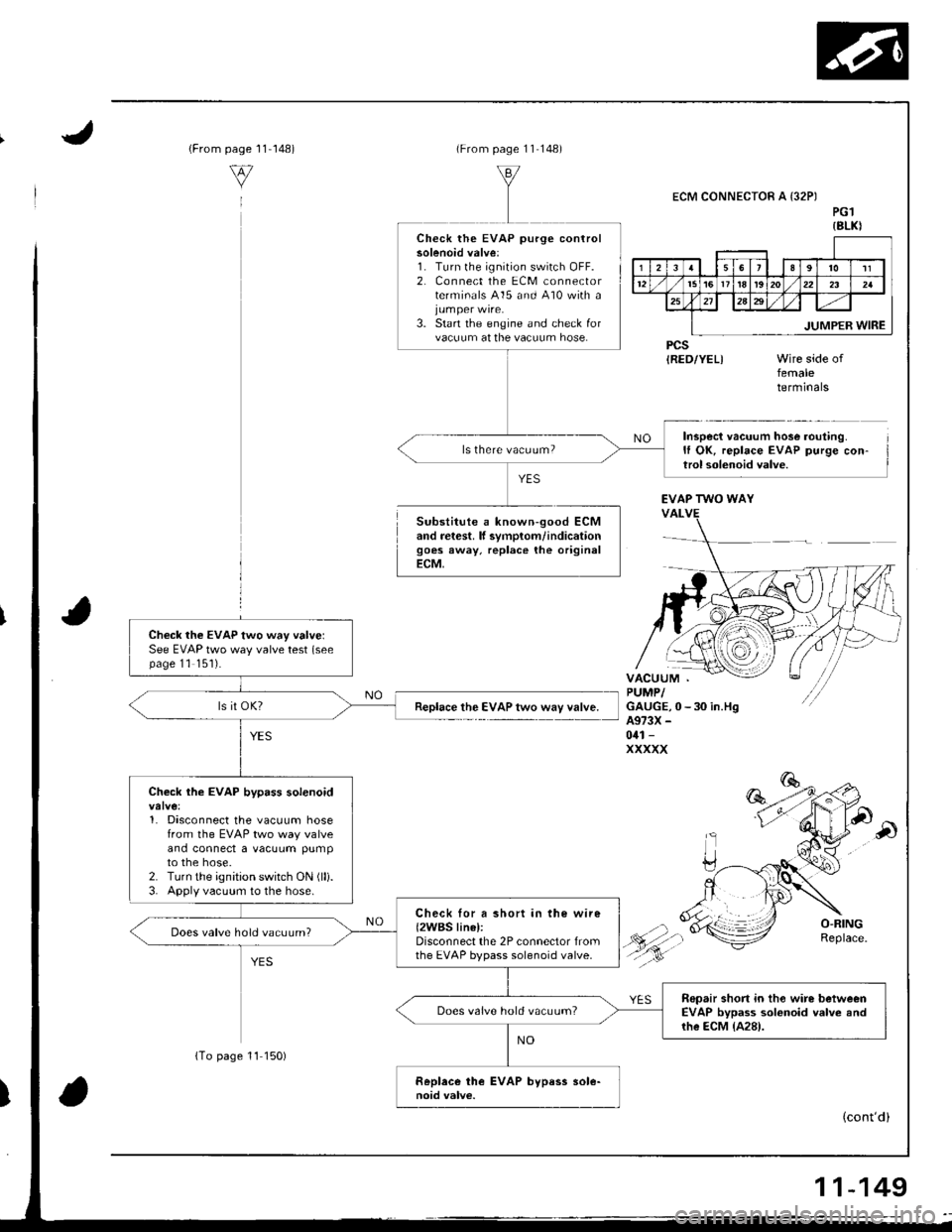
Substitute a known-good ECMand retest. lf svmplom/indicationgoes away, replace the originalECM,
ECM CONNECTOR A {32PIPG1{8LKI
PCSIRED/YEL)femaletermrnars
Inspect vacuum hose routing.It OK, replace EVAP purge con-trol solenoid valve.
Check the EVAP purge controlsolenoid valve:1. Turn lhe ignition switch OFF.2, Connect the ECM connectorterminals 415 and 410 with a
3. Start the engine and check forvacuum at the vacuum hose.
ls there vacuum?
EVAP TWO WAY
Check the EVAP two way valvelSee EVAP two way valve test (seepage 11 '151).
Replace the EVAP two way valve.
Check the EVAP bypass solenoid
1. Disconnect the vacuum hosefrom the EVAP two way valveand connect a vacuum pumpto the hose.2. Turn the ignition switch ON (lli.
3. Apply vacuum to the hose.
Check lor a short in the wire{2WBS linel:Disconnect the 2P connector fromthe EVAP bypass solenoid valve.
Does valve hold vacuum?
Repair short in tho wire betweenEVAP bypass solonoid valve andrhe ECM {A28).
Does valve hold vacuum?
(cont'd)
{To page 11 150)
11-149