ignition HONDA INTEGRA 1998 4.G Manual Online
[x] Cancel search | Manufacturer: HONDA, Model Year: 1998, Model line: INTEGRA, Model: HONDA INTEGRA 1998 4.GPages: 1681, PDF Size: 54.22 MB
Page 475 of 1681
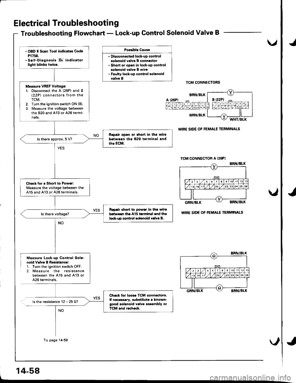
Electrical Troubleshooti n g
Troubleshooting Flowchart - Lock-up Control Solenoid Valve B
Poitibl. Cau3o
. Dbconn.stsd lock-up controlsolenoid valv6 B connectol. Short or open in lock-up cont.ol3olonoid valva B wiro. Faulty lock-up conttol solcnoidvalva BTCM CONNECTORS
WIRE SIDE OF FEMALE TERMINALS
wlRE SIDE OF FEMAIE TERMINALS
Moa3ure Lock-up Control Sol.-noid Vrlv. B R$btanco:1. Turn the ignition switch OFF.2. Measure the reslstancebotween the A15 and A13 or426 terminals.
.. ls the r€sistance 12 -25A?
14-58
u,
NO
. OBD ll Scrn Tool indicrt.3 Cod.P1758.. Self-Oiagnosis E indicato.light blink3 twics.
Moasuro VREF Vohago:1. Disconnect the A (26P) and B(22P) connectors from theTCM.2. Turn the ignition switch ON (ll).
3. Measure tho voltage betweenthe 820 and A13 or 426 termi-nats.
Rapair opan or lhort in iho wirobatwaan tho 820 terminal andth. ECM.ls there approx. 5 V?
Check for a Shon to Powar:Measure the voltage between th€A15 and A13 or A26 terminals.
Rapair .hort to powar in tha wircbatr.,aon tha A15 ta.mlnal and thalock.up control rol.noid valva B.
Chack for loo.. TCM connactoB.It necassrry, 3ub3thuta ! known-good 3olcnoid valve .ir€mbly olTCM .nd r6ch.ck.
To page 14-59
*d
*,
Page 477 of 1681
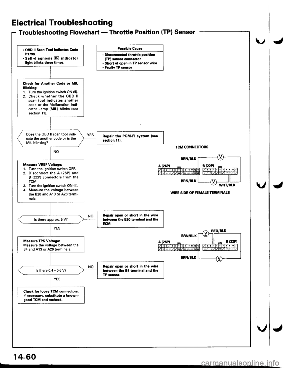
Electrical Troubleshooting
Troubleshooting Flowchart - Throttle PositionITP}Sensor
Po3Cblc C!us.
. Dirc.nn.c.t d throttlo pothion
lTPl ranaor connac'tor. Shon of opan in TP aanror wiro. Faulty TP ianror
TCM CONNECTORS
WIRE SII'E OF FEMAI.I TERMI'TALS
' OBD ll Sc.n Tool indlclto3 CodcP1790.. Soll-di.gnosi. E indic.tollighi blinks tht.e tim*,
Check tor Anoth.r Code or MILBlinking:1. Turn the ignition switch oN (ll).
2. Check whether rhe OBD llscan tool indicatss anothercode or the Malfunction lndi-cator Lamp (MlL) blinks (seo
soction l1).
Ooes the OBD ll scan tool indi-cate the anothor code or is theMIL blinking?
Morrur. VBEF Vohag.:1. Turn the ignition switch OFF.2. Disconnect the A (26P) andB (22P) connectors trom theTCM.3. Turn the ignition switch ON (ll).
4. Measure the voltage b6twsonthe 820 and A13 or 426 termi-nats.
RcpaiJ opon or thort in tha wlJab.tt r..n lho 840 t rlnlnal md lh.ECM.ls there approx. 5 V?
Mer3uro TPs vohrg.:Measure th€ voltage between th684 and A13 or A26 terminals.
Rapair opon oa rhoat in thr wlrab.tw.cn th. B4 t.rmln.l .nd th.TP aansor.ls there 0.4 - 0.6 V?
Ch.ck lor loosa TcM connactorr.ll nocassary, rubditut. r known-good TCM and r.chock.
t26Pl
U
\./
\"/
14-60
.d
{
4
Page 478 of 1681
IJ
v
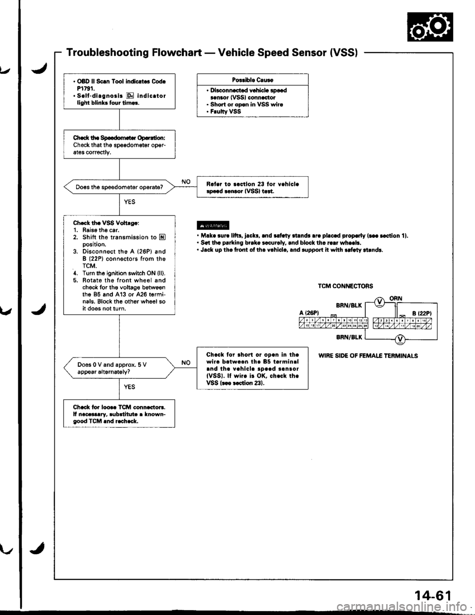
Troubleshooting Flowchart - Vehicle Speed Sensor {VSS)
Pos.ibl. C.u3o
. D|""."-"t"d .r"hl"L 3p*daanaor (VSSI connactol. Short or opan in VSS wira. F.ulty VSS
@. M.k. .ur. 11ft3, l.cl(., .nd ilt ty .l.nds .r. pl.c.d prop€rly (t€a .cction 11.. Srt th. p!.king b..ko rlcur.ly, lnd block thr r..r wh..b.. J.ck up th. t?ont ol ih. yohlcl., lnd .upport it whh rdlty rt.ndr.
WIRE SIDE OF FEMAI.C TERMINALS
. OBD ll Sc.n Tool indlcrt . Cod.Pl791.. s.lt-dl.gno.i. E indicrtorllghi blinkr four tirn.r.
Ch.d( tho Sp..dom.t r Op.r.don:Checkthat the spoedometgr opeFat€s corrsctlv.
R.t.r io ..ctlon 23 lor v.hlcl.!p.!d tlnto. IVSSI t rt.
Ch.ck thr VSS Voh.g.:1. Baise th6 car.2. Shift the transmission to Eposition.
3. Disconn€ct tho A (26P) andB (22P1 conn€ctors from theTCM.4. Turn the ignition switch ON (ll).
5. Rotate the front wheel sndcheck for th6 voltage botws€nthe 95 and A'13 or 426 termi-nals. Block th€ oth6r wheel soit does not turn.
Chack tor ahorl or opan in ihawlra batwaan tha 85 tarmin.land tha vahicla tpaad tanror{VSSI. ll wirc i! OK, ch.ck th.VSSk ot ction 23).
Chack io. loo.c TCM conn.ctors.It nacasaary. rubditut . known-good TCM .nd r.ch.ck.
TCM CONNECTORS
14-61
Page 479 of 1681
Electrical Troubleshootin g
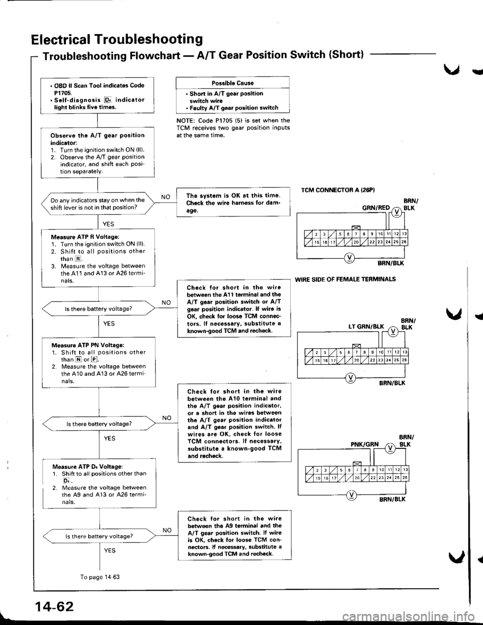
Troubleshooting Flowchart - A/T Gear Position Switch (Short)
Llu
Po$ible Cause
' Shon in A/T gea. position
switch wire. F.ulty A/T g€at position switch
NOTE: Code P1705 (5) is set when theTCM receives two gear position inputs
at the same time.
TCM CONNECTOR A {26FI
WIRE SIDE OF FEMALE TERMINALS
{
Measure ATP D. Voltagel1. Shift to all positions other than
o;.2. Measure the voltage betweenthe Ag and 413 or A26 termi'nals.
{
14-62
. OBO ll Scan Tool indicates CodeP1705.. S6lt-diagnosis Pr-,.. indicatorlight blinks five times.
Observe the A/T gear position
indicator:1. Turn the ignition switch ON {ll).2. Observe the A/T gear position
indicator, and shift each Posi-tion separately.
The syslem is OK at this time.Ch€ck the wite hotn€ss for dam-a9e,
Do any indicators stay on when the
shift lever is not in that position?
Measure ATP R Voltage:1. Turn the ignition switch ON (lli.
2. shitt to all positions otherthan E.3. Measure the voltage betweenthe A11 and 413 or 426 termi-nals.Check for short in ihe wire
betwe€n the 411 termin.l and theA/T gear position switch or A/Tg6ar position indicator. lf wire is
OK, check tor lo6e TCM connec-
tors. lf necessary, substitute a
known-good TCM and rech€ck.
ls there battery voltageT
Measure ATP PN Volt.go:1. Shift to all positions otherthan E or E.2. Measure the voltage betweenthe 410 and A13 or 426 terminals.
Check for 3hort in the wire
between the A10 tetminal andthe A/T gear position indicator,or a short in the wir63 betweenthe A/T gear position indicatorand A/T g€ar position switch. lfwires are oK, check for looseTCM connecto13. lf necessarv,3ubslitute a known-good TCM
and recheck.
Check for 3hort in the wirebetween the Ag terminal and thoA/T gear po3ition switch. lf wireis OK, check tor loose TCM con-neclors. ll necessary, substitute aknown-good TCM and recheck.
To page 14 63
Page 481 of 1681
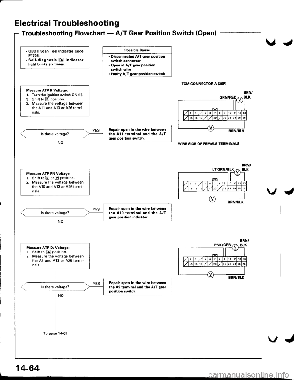
Electrical Troubleshooting
Troubleshooting Flowchart - A/T Gear Position Switch(Openl
Po3.ible Cause
. Di"""."."i"d A/T ,"". p""iti
switch connoctor. Open in A/T ge.r position
switch wire. Faulty A/T gear position switch
TCM CONN€CTOR A (26PI
WIRE SIDE OF FEMAI.E TERMINALS
Measuro ATP D. Voltage:1. Shift to E position.2, Measure the voltage betweenthe Ag and A13 or 426 termi-nals.
ls there voltage?
14-64
BRN/BLK
NO
. OBD ll Scsn Tool indicate. CodeP1706.. Self-diagnosis E indicatorlight blinks six times.
Measuro ATP R Voltago:1. Turn the ignition switch ON (ll).
2. Shift to E position.
3. Nleasure the voltage betweenthe 411 and 413 or 426 terminals.
Repair open in the wire bctweanthe A11 te.minal and the A/Tgear position switch.
Moasure ATP PN Volt.ge:1. Shift to E or E position.
2. Measure the voltage betweenthe 410 and A13 or 426 termi-nals.
Ropai. open in the wirs betweentho A10 terminal snd the A/Tgear position indicator.
Repair open in the wire betweenthe Ag terminal end the A/T g€arpo3ition switch.
To page 14-65
VJ
Page 483 of 1681
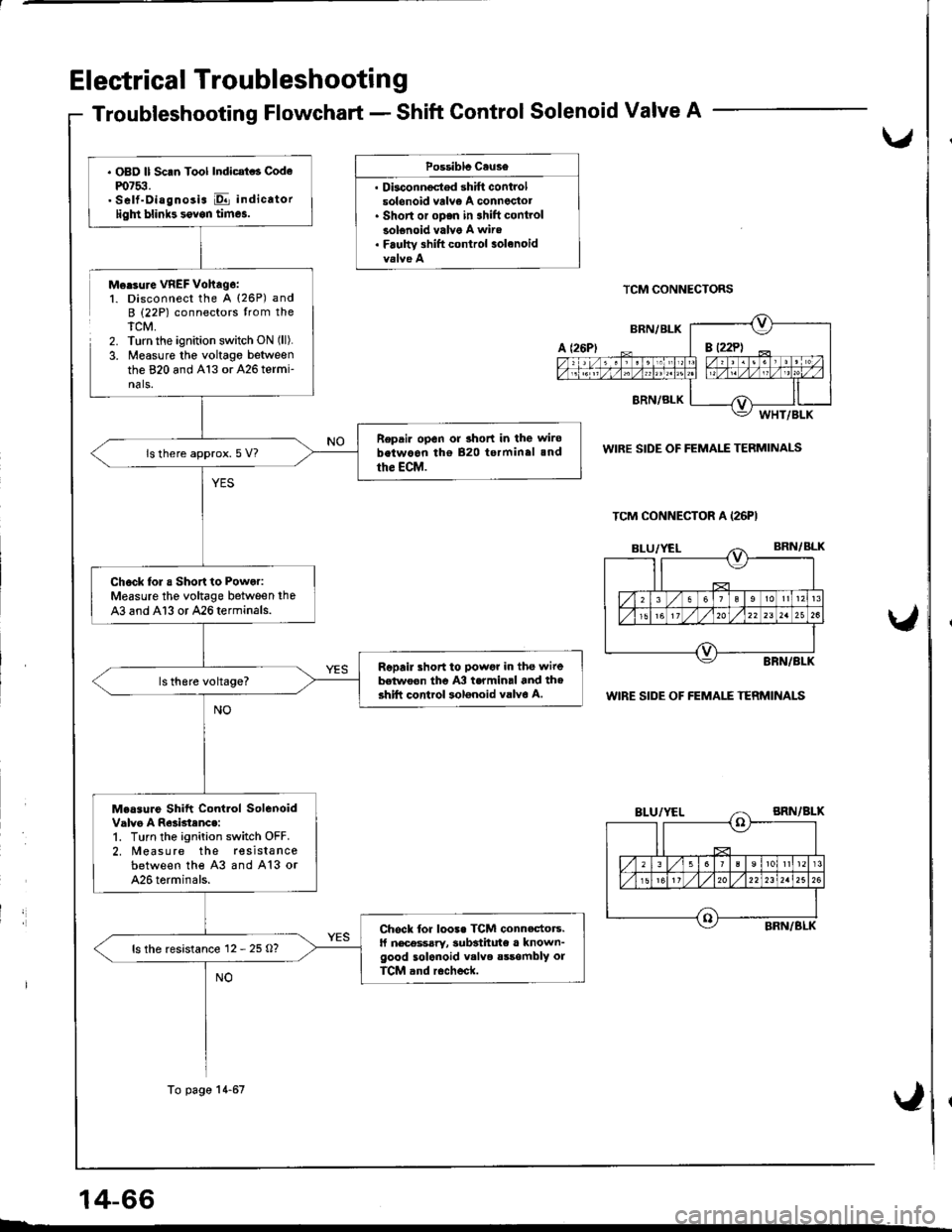
Electrical Troubleshootin g
Troubleshooting Flowchart - Shift Gontrol Solenoid Valve A
,
Possiblc Cause
. Dbconnoctod shift controlsolonoid vrlv€ A conneclot. Short or oDen in 3hift controlsolenoid valve A wire. Faulw 3hift control solanoid
Morsure VREF Vohag6:1. Disconnect the A (26P) andB (22P) connectors trom theTCM,2. Turn the ignition switch ON (ll).
3. Measure the voltage betweenthe 820 and A13 or 426 termi-nals.
TCM CONNECTORS
WIRE SIDE OF FEMALE TERMINALS
WIRE SIDE OF FEMALE TERMINALS
14-66
TCM CONNECTOR A (26PI
. OBD ll Scan Tool Indicat . Codem7$.. Self-Diagnosis E indicatorligln blinb sovon times.
Repair open or 3hort in the wirobetwoon tho 820 terminal 3nd
the ECM.ls there approx. 5 V?
Chock lol a Short to Power:Measure the voltage between the
43 and Al3 or 426terminals.
Repail short to powgr in the wirebelwoon the A3 termin.l and th6shift control solonoid valvo A.
Measure Shift Contlol SolenoidValvo A R63btenc.:1. Turn the ignition switch OFF.2. Measure the resista ncebetween the 43 and A13 or426 torminals.
Chock for loo3. TCM connectors.ll nec€ssary, 3ubsthute a known-good solenoid v.lve sssombly orTCM and r6check.
ls the resistance 12 - 25 O?
To page 14-67
Page 485 of 1681
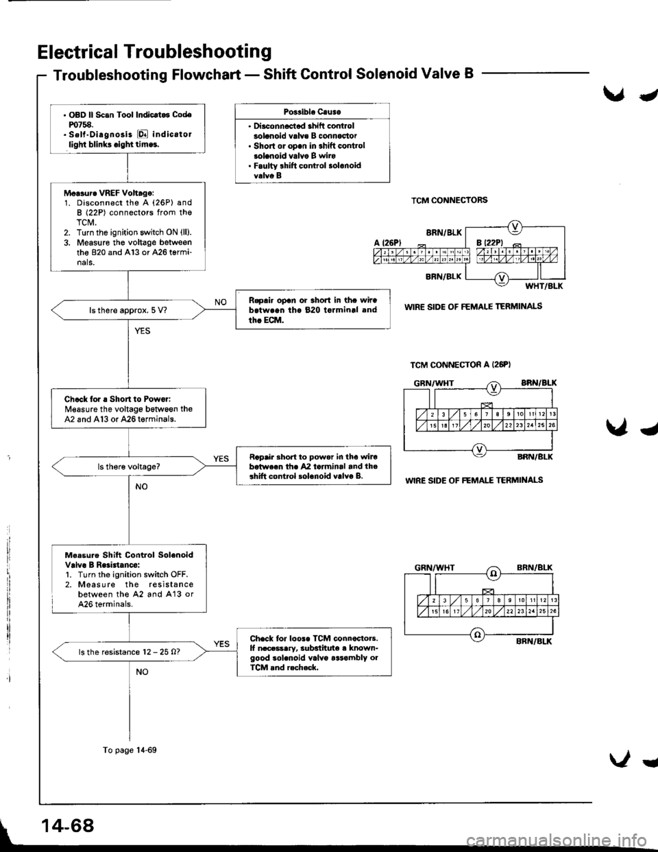
Electrical Troubleshootin g
Troubleshooting Flowchart - Shift Control Solenoid Valve B
Po3sibl. Cauao
' Diaconncctad ahift controlsolanoid valve B connoc'tor. Short ol op.n in shift contlolsolanoid valvo B wiro. Faulty lhift control solonoidvalvo B
TCM CONNECTORS
WIR€ SIDE OF FEMALE TERMINALS
WIRE SIDE OF FEMAI."E TERMII{ALS
Me.sure Shift Control Solenoidvalvo B Raliatanco:l. Turn the ignition switch OFF.2. Measure the resistancebetween the 42 and A'13 orA26 terminals.
J
Ug
TCM CONNECTON A (26PI
. OBD ll Scan Tool Indicrt.3 Codem758.. sell"Diagnosi3 [Q indicatorlight blink3.igl|ttlm.!.
Moasur. VREF Voh.go:1. Disconnect the A (26P) andB (22P) connectors from thoTCM.2. Turn the ignition switch ON (lll.
3. Measure the voltage betweenthe 820 and Al3 or A26 termi-nals.
R.pair opan or 3hort in thc wirab.twrqn th. 820 tormin.l and
th. ECM.ls there approx. 5 V?
Check for . Short to Powor:Measure the voltage bstween theA2 and A13 or 426termin8ls.
Rapair Bhort to power in tho wilobotwecn thr 42 laiminal and th.3hift control solanoid valvo B.
Chack lor loos. TCM connactoB.lf n.ceasary, subsiituto a known-good sol.noid valv6 tasambly olTCM rnd rech.ck.
ls the resistance 12 - 25 O?
To page 14-69
Ug
Page 489 of 1681
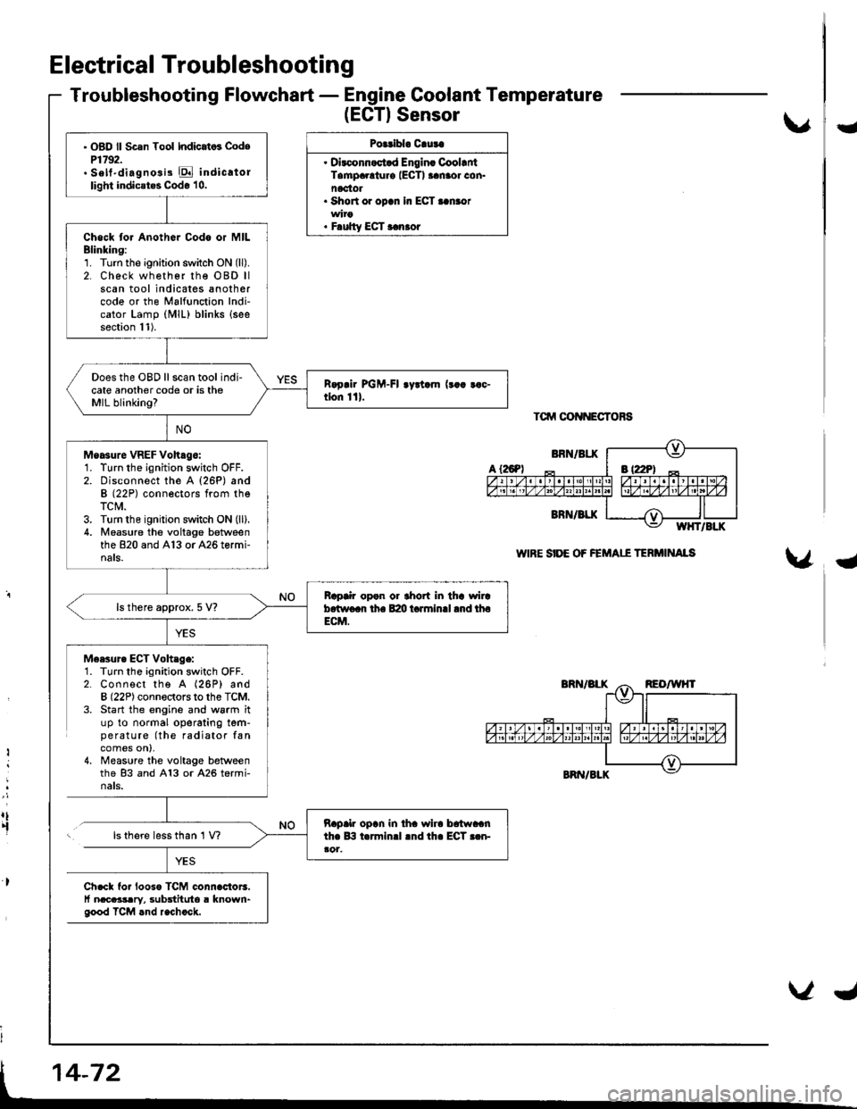
Electrical Troubleshooting
Troubleshooting Flowchart - Engine Coolant Temperature
(EGTISensor
Polribl. Cluta
. Dirconnoct.d Engin. CoollntTampaolur€ IECTI aanaor con.noctot. Short or opcn In ECT..n.or
. F.ulty ECT r.n.or
Tctrrt oot{NEcToRs
WIRE SIDE OF FEMAII TERi'IINAIS
U
{
M6esur. ECT Voh.ge:1. Turn the ignition switch OFF.2. Connect the A (26P) andB (22P) connectors to the TCM.3. Start the engine and w6rm ituP to normal operating tem-pe ratu re (the radiator fancomes on),4, Measure the voltage betweenthe 83 and A13 or A26 termi-nats.
Ii
:
rt.fls there less than 1 V?
Ch.cl fo. looso TCM connac{or3,t nacaasary, substituto a known"good TCM rnd r.chock.
' OBD ll Scsn Tool Indicat6 CodeP1792.. Sett'diagno3i3 E indicatollight indicates Code 10.
Chock tor Anothor Codo or MILBlinking:1. Turn the ignition switch ON (ll).
2. Check wh€ther rhe OBD llscan tool indicates anothercode or the Malfunction Indi-cator Lamp (MlL) blinks (see
section 11).
Does the OBD ll scan tool indi-cate another code or is theMIL blinking?
Moasure VREF Voh.go:1. Turn the ignition switch OFF.2. Disconnect the A {26P) andB (22P) conneotors from theTCM.3. Turn the ignition switch ON (ll).
4. Measu.e the voltage betweenthe 820 and A13 or A26 tormi-nals.
Bap|ir open or thort in tha wircb.two.r th. B:m t.rminll .nd thoECM.
ls there approx. 5 V?
napalr opln in iha wlra brtwaanthe lB t.rminrl lnd th. ECT r.n-ao1.
Page 490 of 1681
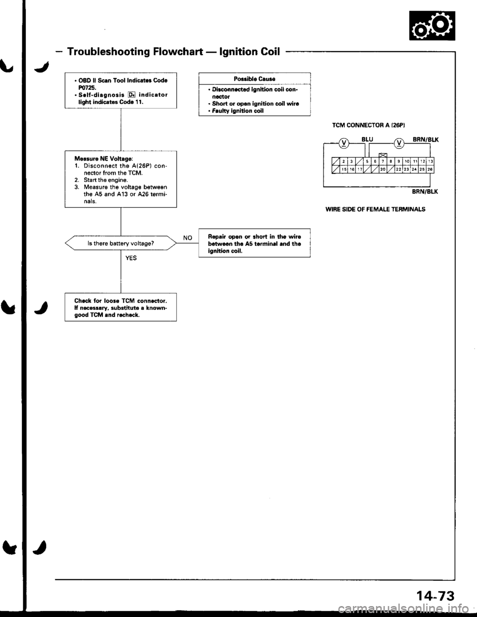
. OBD ll Sc.n Tool Indicrt$ cod.m725.. S.lf.di.gnosi3 E indicetotlight indicet$ Cod. 'l 1.
Motsure NE Vohago:1. Disconnect the A{26P) con-nector from the TcM.2. Stan tha €ngine.3. Measurg the voltage betwegnthe A5 and Al3 or 426 termi-nals.
Rapair opan or lhort in tho wirabctwo6n tho AS tarminal and tholgnhion coil.ls there banery voltage?
Chack tor loose TCM connector.lf necasllry, 3ub3titule a known-good TCM snd recheck.
- Troubleshooting Flowchart - lgnition Coil
JU
Poaaible Cau3€
' Di.conn€c{od ignition coil con.nactot. Short or opcn ignition coil wira. Frulty ignition coil
WIRE SIDE OF FEMAI,T TEBMINALS
tt
tt
BRN/BLK
14-73
Page 491 of 1681
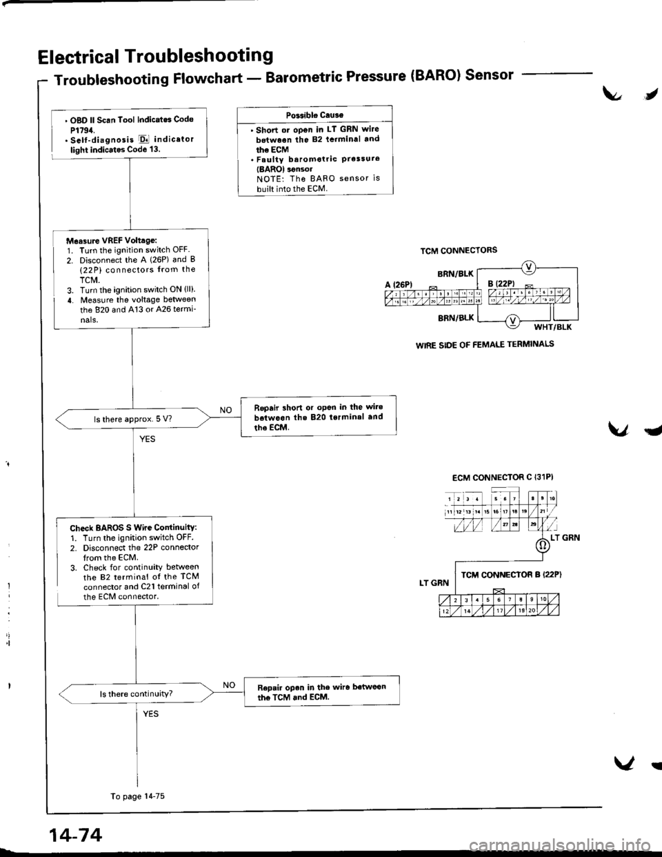
Electrical Troubleshooting
Troubleshooting Flowchart - Barometric Pressure (BARO) Sensor
t\l,
l
'|
. OBD ll Scan Tool lndicatos Code
P1794.. Self-diagnosis El indicator
light indicatos Code 13.
Check BAROS S Wire ContinuitY:1. Turn the ignition switch OFF.
2. Disconnect the 22P connedortrom the ECM.3. Check for continuity betweenthe 82 terminal ot the TCM
connector and C21 terminal of
the ECM connector.
PGsible cau3€
' Short ot oDen in LT GRN wite
betwoen the 82 lcrminal and
ihe ECM. Faulty baromotric PrelsureIBAROI ignsolNOTE: Tho BAFO sensor is
built into the ECM.
VqJ
WIRE SIDE OF FEMALE TERMINALS
Measure VREF Volttge:1. Turn the ignition switch OFF.
2. Disconnect the A (26P) and B(22 P) connectors from the
TCM.3. Turn the ignition switch ON {ll}.
4. Measure the voltage between
the 820 and 413 or 426 termi-
nals,
Repair shon or oPen in the wite
betwcon the 820 tsrminal and
tho EcM.ls there approx.5 V?
Repair open in the wiro betwoon
the TcM and ECM.ls there continuity?
To page 14-75
14-74
V!