HONDA INTEGRA 1998 4.G Workshop Manual
Manufacturer: HONDA, Model Year: 1998, Model line: INTEGRA, Model: HONDA INTEGRA 1998 4.GPages: 1681, PDF Size: 54.22 MB
Page 331 of 1681
F
I
Fuel Supply
PGM-Fl Main
System
Relay (cont'd)
\
lb
i
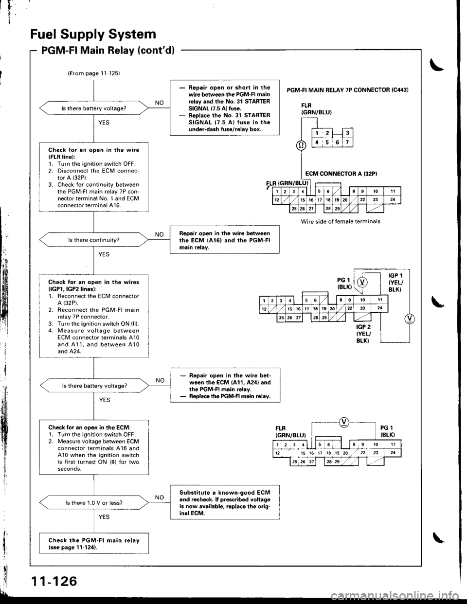
(From page 11 125)
- Reprir open or short in thewire between the PGM-FI mainrelay and the No. 31 STARTERSIGNAL {7.5 A} tuse.- RoDlace the No. 31 STARTERSIGNAL {7.5 A) fuse in theunder-dash luse/relav box,
Check for an open in the wire
{FLR line}:1. Turn the ignation switch OFF.2. Disconnect the ECM connector A (32P).
3. Check for continuity betweenthe PGM-FI main relay 7P con-nector terminal No. 1 and ECMconnector terminal A16-
Repair open in the wire betweenthe ECM (A161 and the PGM-FImein relay,ls there continuity?
Check for an open in the wires{lGPl, lGP2lines}:1. Reconnect the ECM connectorA (32P).
2. Reconnect the PGM-Fl mainrelay 7P connector.3. Turn the ignition switch ON {ll).4. Measure vo ltage betweenECM connector terminals A10and A11, and between A10and 424.
- Repaar open in lhe wir€ bet-ween the ECM 1A11, A24l andthe PGM-FI main relay.- Repldce the PGM-FI main relay.
ls there battery voltage?
Substitute a known-good ECMand recheck. It prescribed vohageis now available. roplace lhe o.ig-inalECM.
ls there 1.0 V or less?
Check the PGM-Fl main relaylsee page 11-124).
PGM.FI MAIN BELAY 7P CONNECTOR IC443I
FLR
FLR
Wire side of temale terminals
Check tor en open in the ECM:1. Turn the ignition switch OFF.2. Measure voltage betlveen ECMconnector termanals A16 andA10 when the ignition switchis first turned ON (ll) for two
IGRN/BLU}
o
1,2!t5i6
:cM CONNEi)TOR A I32P)
I23sl6a9to11
1215lor 17 18t920/22232a
25262l12329
PGl(8LKI
IGP 1
{YEL/BLK}
(
t356I
t5161t la192022
25a
IGP 2{YEL/BLKI
12 15 15 17 18 19 20 .r 22 23
Page 332 of 1681
1r
;
J
I
Fuel Tank
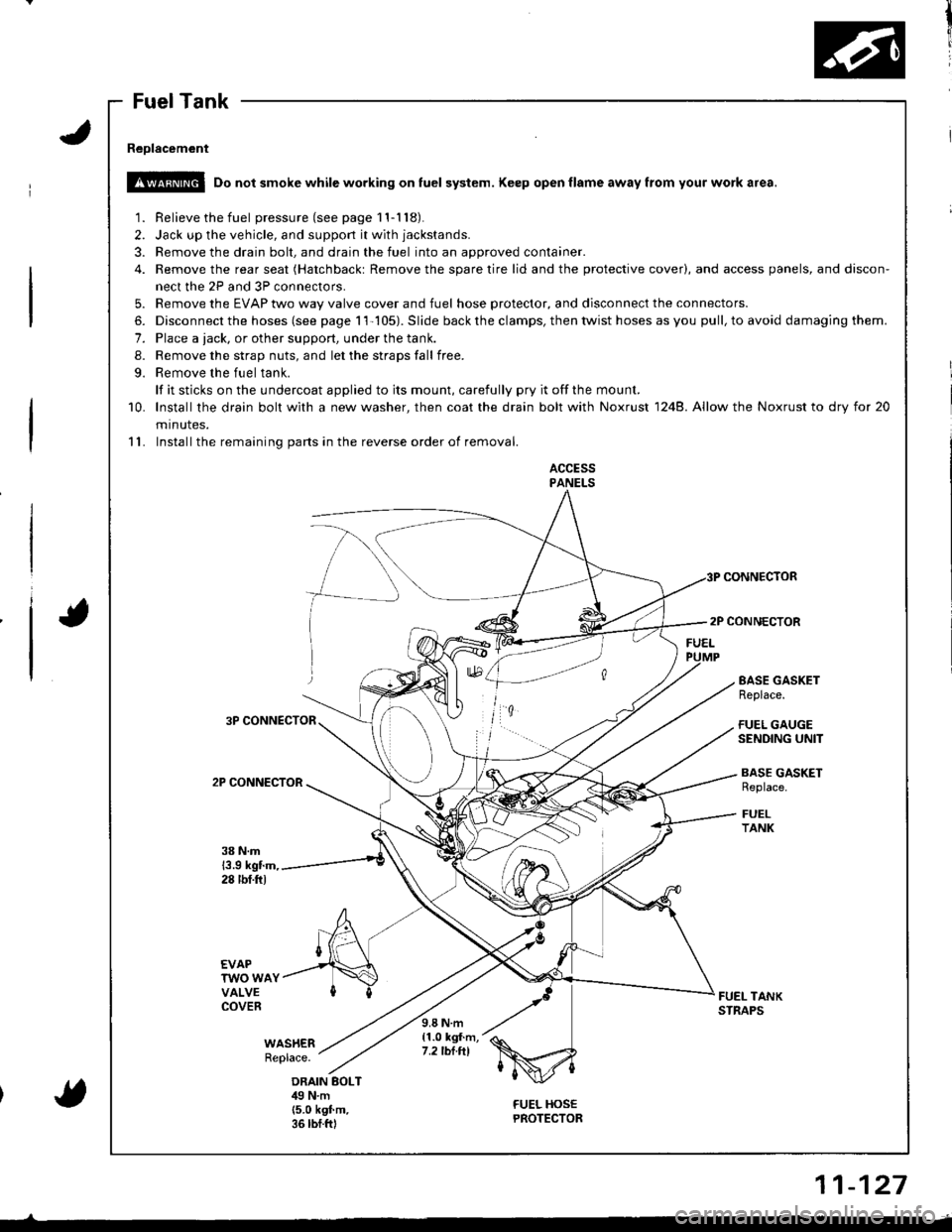
Reolacement
!!@ Do not smoke while working on fuel system. Keep open flame away from your work a.ea.
1. Relieve the fuel pressure(seepagell-118).
2. Jack up the vehicle, and support it with jackstands.
3. Remove the drain bolt, and drain the fuel into an approved container.
4. Remove the rear seat (Hatchbackt Remove the spare tire lid and the protective cover), and access panels, and discon-
nect the 2P and 3P connectors.
5. Remove the EVAP two way valve cover and fuel hose protector, and disconnect the connectors.
6. Disconnect the hoses (see page 11-105). Slide back the clamps, then twist hoses as you pull, to avoid damaging them.
7. Place a tack, or other support, under the tank.
8. Remove the strap nuts, and let the straps fall free.
9. Remove the fuel tank.
lf it sticks on the undercoat applied to its mount, carefully pry it offthe mount.
10. lnstallthe drain bolt with a new washer, then coat the drain bolt with Noxrust 1248. Allow the Noxrust to dry tor 20
minutes.
11. Installthe remaining parts in the reverse order of removal.
ACCESSPANELS
CONNECTOR
2P CONNECTOR
3P CONNECTOR
2P CONNECTOR
EASE GASKETReplace.
FUEL GAUGESENDING UNIT
BASE GASKETReplace.
FUELTANK
38 N.m13.9 kgtm,28 tbf.ftl
EVAPTWO WAYVALVECOVERFUEL TANKSTNAPS
WAS}IERReplace.
9.8 N.m{1.0 kgf.m,7.2 tbt.tll
ORAIN BOLTilg N.m(5.0 k9f.m.36 rbf.ftl
FUEL HOSEPROTECTOR{
11-127
Page 333 of 1681
r
Intake Air System
System DescriptioSystem uescnpllon
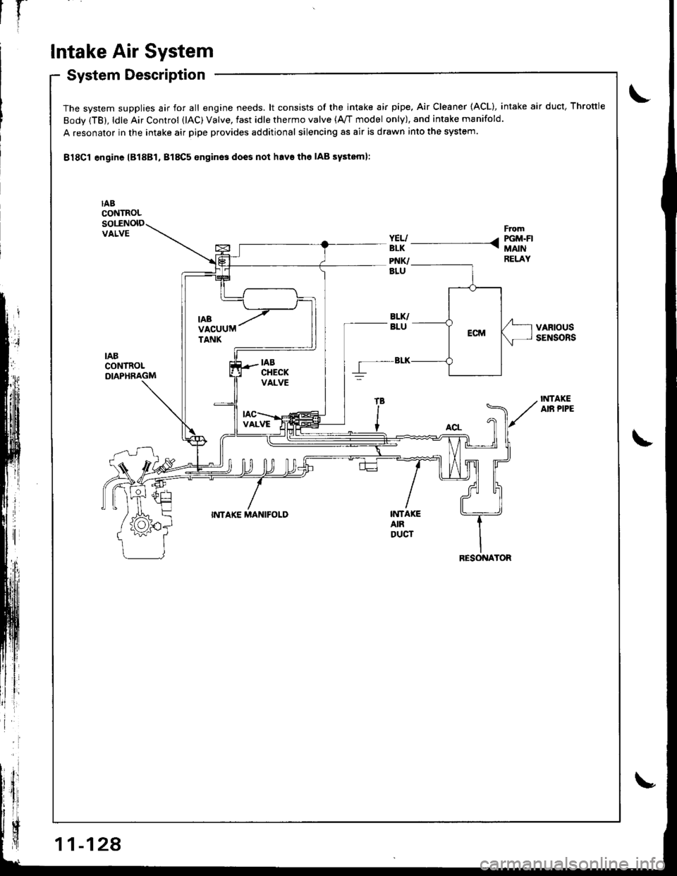
The system supplies air for all engine needs. lt consists of the intake air pipe. Air Cleaner (ACL), intake air duct, Throttle
Body (TB), ldle Air Control (lAC) Valve, fast idle thermo valve (A,/T model only), and intake manifold.
A resonator in the intake air pipe provides additional silencing as air is drawn into the system.
B18Cl engine lB18Bl, B18C5 enginos does not havs the IAB systeml:
IABCONTROLsollNolDVALVE
VARIOUSSENSORS
IABCONTROLDIAPHRAGM
IiITAKEAIR PIPE
INTAKE MANIFOLDINTA|(EAIRDUCT
RESONATOR
Page 334 of 1681
Air Cleaner (ACLI
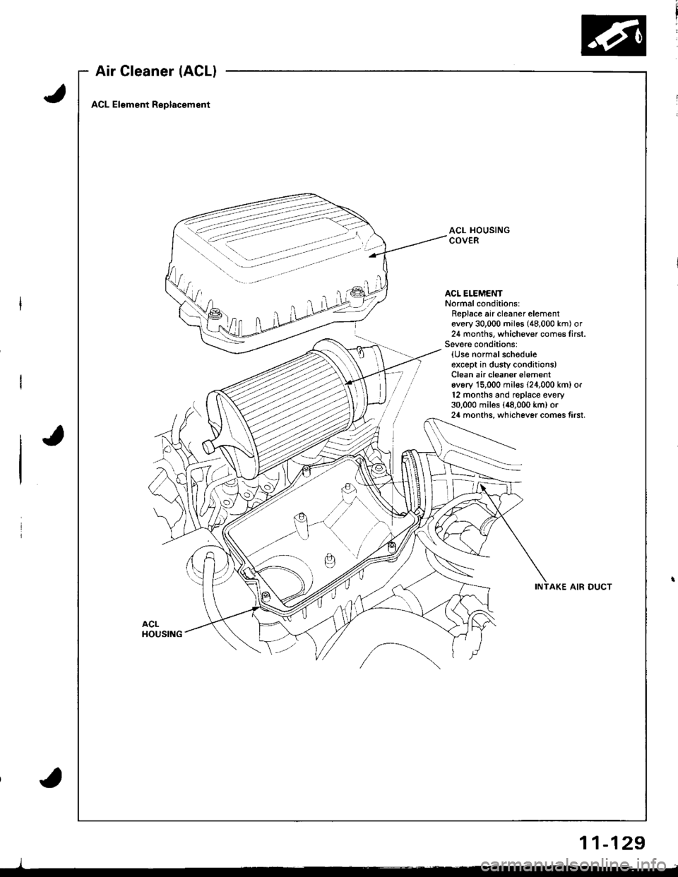
ACL Element Replacement
ACL HOUSINGCOVER
ACL ELEMENTNormal conditions:Replace air cleaner elementevery 30,000 milos (48,000 km) or24 months, whichever comes first.Severe cond;tions:{Use normalschoduleexcept in dusty conditions)Clean air cleaner elementev6ry 15,000 mil€s {24,000 km} or12 months and replace every30,000 miles (48,000 km) or24 months, whichever comes tirst.
INTAKE AIR DUCT
)
11-129
Page 335 of 1681
l-
Intake Air System
LOCKNUT
DEFLECTION10-12mmBIA- 112in.l
lf deflection is not within specs, loosen the locknut,
turn the adjusting nut until the deflection is as spec-
ified, then retighten the locknut.
With the cable properly adiusted, check the throttle
valve to be sure it opens fully when you push the
accelerator pedal to the floor. Also check the throt-
tle valve to be sure it returns to the idle position
whenever you release the accelerator pedal.
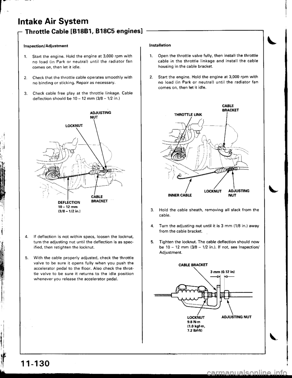
Throttle Cable IB18B1, 818C5 engines]
Inspection/Adiustment
1. Start the engine. Hold the engine at 3,000 rpm wirh
no load (in Park or neutral) until the radiator tan
comes on, then let it idle.
2. Check that the throttle cable operates smoothly wilh
no binding or sticking. Repair as necessary.
3. Check cable free play at the throttle linkage. Cable
deflection should be 10 - 12 mm (3/8 - 'l12 in.l
ADJUSTINGNUT
t
il
qr
ll1 1-130
!!
TING NUT
\lnstallation
1. Open the throttle valve fully, then install the throttle
cable in the throttle linkage and install the cable
housing in the cable bracket.
2. Start the engine. Hold the engine at 3,000 rpm with
no load (in Park or neutral) until the radiator fan
comes on, then let it idle.
INNER CABLE
Hold the cable sheath, removing all slack from the
caote.
Turn the adjusting nut until it is 3 mm {1/8 jn.) away
from the cable bracket.
Tighten the locknut, The cable deflection should now
be 10 - '12 mm (3/8 - 'll2 in.). lf not, see Inspection/
Adjustment.
3 mm 10.12 inl
u
4.
AD
\
JUSLOCKNUT9.8 N.m(1.0 kgt.m,7,2lbl.ttl
CABI.E
CABI,E BMCKET
Page 336 of 1681
't.
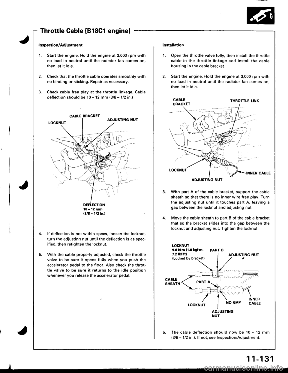
Inspsction/Adiustmsnt
Stan the engine. Hold the engine at 3,000 rpm with
no load in neutral until the radiator fan comes on,
then let it idle.
Check that the throttle cable operates smoothly with
no binding or sticking. Repair as necessary.
Check cable free play at the throttle linkage. Cable
deflection should be 10 - 12 mm (3/8 - 1/2 in.)
DEFTECTION10- 12 mmBIA-112in.l
lf deflection is not within specs, loosen the iocknut.
turn the adjusting nut until the deflection is as spec-
ified, then retighten the locknut.
With the cable properly adjusted, check the throttle
valve to be sure it opens fully when you push the
accelerator pedal to the floor. Also check the throt-
tle valve to be sure it returns to the idle position
whenever you release the accelerator pedal.
CABLE BBACKET
lnstallation
Open the throttle valve fully, then install the throttle
cable in the throttle linkage and install the cable
housing in the cable bracket.
Stan the engine. Hold the engine at 3,000 rpm with
no load in neutral until the radiator fan comes on,
then let it idle.
l.
3.
5.
CABLEBRACKETTHROTTLE LINK
ADJUSTING NUT
With part A of the cable bracket. support the cable
sheath so that there is no inner wire tree plav. Turn
the adjusting nut until it touches part A, leaving a
gap between the locknut and adjusting nut.
Move the cable sheath to oart B of the cable bracket
that so the bracket slides into the gap between the
locknut and adjusting nut. Tighten the locknut.
LOCKNUT9.8 N.m 11.0 kgf.m, PART 87.2lbf.frl(Lockod by bracketl
CABLESHEATH
NO GAPINNERCABLE
ADJUSTINGNUT
The cable deflection should now be 10 - 12 mm(318 - 112 in.l. lf not. see Inspection/Adjustment.
ADJUSTING NUT
1 1-131
Page 337 of 1681
In
Intake Air System
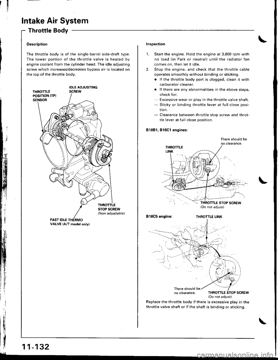
Throttle Body
$;
Description
The throttle body is of the single barrel side-draft type.
The lower portion of the throttle valve is heated by
engine coolant from the cylinder head. The idle adjusting
screw which increases/decreases bypass air is located on
the top ot the thronle body.
IDLE ADJUSTINGSCREW
THROTTLESTOP SCREW(Non-adjustable)
FAST IDLE
| | .o clearance. THRoTTLE SToP scREw
{ | | _ .lDonotadiust)
| | y:::::::T,"9":::.'"Tl::f ,::i1::"1" fllyll-'n"
VALVE {A/T model onlv}
Inspection
1. Start the engine. Hold the engine at 3,000 rpm with
no load {in Park or neutral) until the radiator fan
comes on, then let it idle.
2. Stop the engine, and check that the throttle cable
operates smoothly without binding or sticking.
. lf the throttle body pon is clogged, clean it with
carburetor cleaner.
. lf there are any abnormalities in the above steps,
check for:
Excessive wear or play in the throttle valve shaft.- Sticky or binding throttle lever at full close posi-
tion.- Clearance between throttle stop screw and throt-
tle lever at fullclose position.
81881, Bl8Cl engines:
There should beno clearance.
818C5 engine:THROTTLE LINK
There should be
throttle valve shaft or if the shaft is binding or sticking.
glL-
Page 338 of 1681
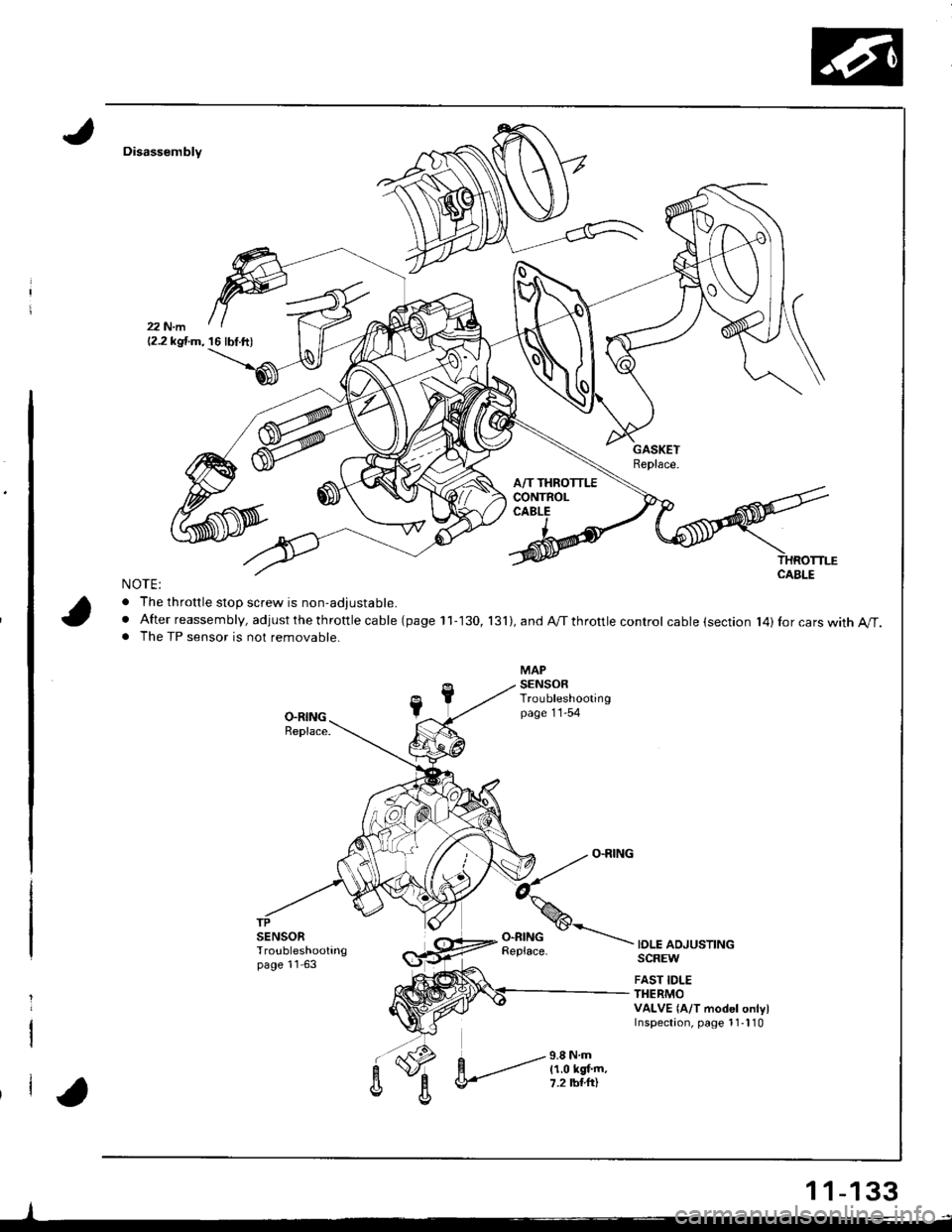
Disassembly
NOTE:
. The throttle stoD screw is non-adiustable.
. After reassembly, adjust the th rottle ca ble (page 11-130, 131),andA/Tthrottlecontrol cable (section l4)Ior cars with A/T.. The TP sensor is not removable.
IOLE ADJUSTINGSCREW
FAST IDLETHERMOVALVE {A/T model onlylInspectaon, page 1 1-l 10
-l
12.2 kgf.m, 16 lbf.ft)
1 1-133
Page 339 of 1681
'{[
'll
I
l'
)l
t,t
H
Ili
Intake Air System
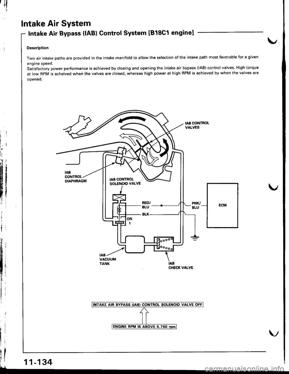
Intake Air Bypass (lAB) Control System [818C1 enginel
Descriplion
Two air intake oaths are erovided in the intake manifold to allow the selection of the intake path most favofable for a given
engine speed.
Satjsfactory power performance is achieved by closing and opening the intake air bypass (lAB) control valves. High torque
at low RpM is acheived when the valves are closed, whereas high power at high RPM is achieved by when the valves are
opened.
IAB CONTROLVALVES
ECM
illf1l
i 11-134
--_
CHECI( VALVE
Page 340 of 1681
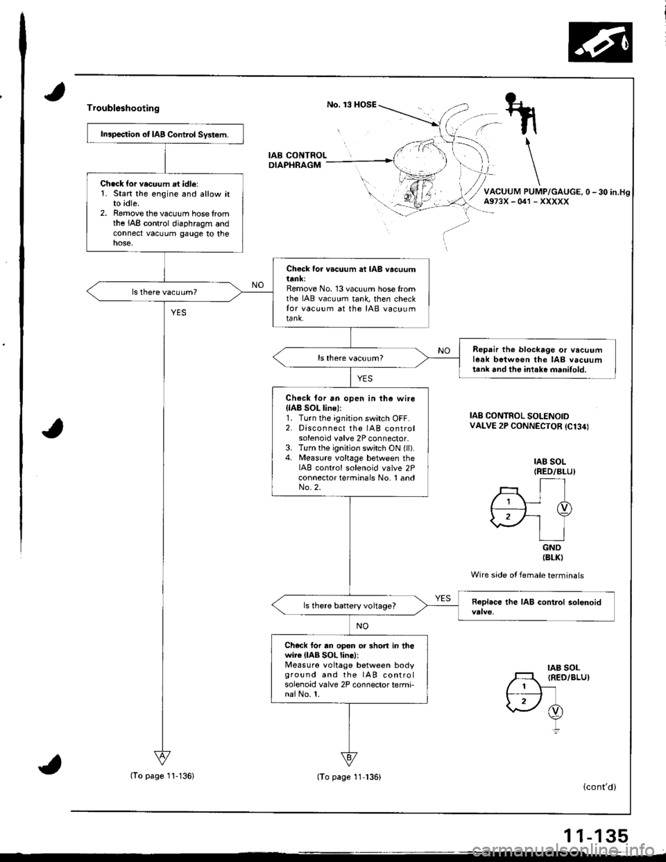
Troublsshooting
IAB CONTROLDIAPHRAGM
Inapection ot IAB Control System.
Chack {or vacuum at idle:1. Stan the engine and allow itto idle.2. Romove the vacuum hose fromthe IAB control diaphragm andconnect vacuum gauge to thenose,
Check to. vacuum at IAB vacuumttnl;Remove No. 13 vacuum hose fromthe IAB vacuum tank, then checkfor vacuum at the IAB vacuumtank.
Repair th€ blockage or vacuuml6ak between the IAB vacuumtenk 6nd the intake manifold.
Check for an open in the wirellAB SOL line):1. Turn the ignition switch OFF.2. Disconnect the IAB controlsolenoid valve 2P connector.3. Turn the ignition switch ON (ll).4. Measure vohage between theIAB control solenoid valve 2Pconnector terminals No, 1 andNo.2.
ls there battery voltage?
Chack for rn op€n or 3hort in thewire (lAB SOL line):Measuro voltage between bodyground and the IAB controlsolenoid valve 2P connector termi-nai No. 1.
IAB SOL(RED/BLUI
rt./; Ir I-TD,2F-' Y\.\/ | ]IGND(BLKI
Wire side ot female terminals
IAB CONTROL SOLENOIDVALVE 2P CONNECTOR {C134)
IAB SOLIRED/BLU)
(cont'd)
11-135
(To page I'l-136)(To page 11.136)