HONDA INTEGRA 1998 4.G Workshop Manual
Manufacturer: HONDA, Model Year: 1998, Model line: INTEGRA, Model: HONDA INTEGRA 1998 4.GPages: 1681, PDF Size: 54.22 MB
Page 361 of 1681
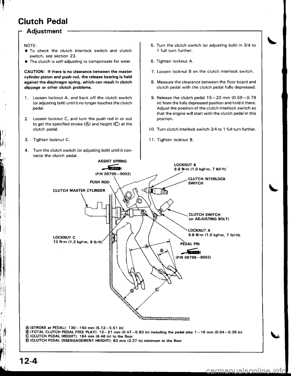
Clutch Pedal
Adjustment
NOTE:
a To check the clutch interlock switch and clutch
switch, see section 23.
a The clutch is self-adjusting to compensate Ior wear.
CAUTION: ll there is no clealance between the master
cylinder piston and push rod, the release bearing is held
against the diaphragm spring, which can result in clutch
slippage or other clutch problems.
1. Loosen locknut A, and back off the clutch switch
(or adjusting bolt) until it no longer touches the clutch
peoal.
2. Loosen locknut C. and turn the push rod in or out
to get the specified stroke (@) and height {O) at the
clutch Dedal.
3. Tighten locknut C.
4. Turn the clutch switch (or adjusting bolt) until it con-
tacts the clutch pedal.
ASSIST SPRING
@{
{PiN 08798-9002t
(STROKE at PEDAL): 130-140 mm (5.12-5.51 in){TOTAL CLUTCH PEDAI- FREE PLAYI: 12-21 mm (0.47-0.83 inl including tho p6dal play{CLUTCH PEDAL HEIGHT): 164 mm 16.46 inl to the tloor(CLUTCH PEDAL DISENGAGEMENT HEIGHTI: 83 mm {3.27 inl minimum to the floo.
t?
5.Turn the clutch switch (or adjusring bolt) in 3/4 to
1 full turn further.
Tighten locknut A.
Loosen locknut B on the clutch interlock switch.
Measure the clearance between the floor board and
clutch pedal with the clutch pedal tully depressed.
Release the clutch pedal 15-20 mm (O.59-O.79
in) from the fully depressed position and hold it there.
Adjust the position of the clutch interlock switch so
that the engine will stan with the clutch pedal in this
position.
Turn clutch interlock switch 3/4 to 1 full turn further.
Tighten locknut B.
9.
6.
7.
8.
10.
11.
LOCKNUT B9.8 N.m 11.0 kgt.m, 7 lbl.ft)
CLUTCH INTERLOCKswrTcHPUSH ROD
CLUTCH MASTER CYLINDER
CLUTCH SWITCH(or AOJUSTING BOLT)
LOCKNUT A9.8 N.m (1.0 kgf.m, 7 lbt.frl
l
{P/N 0879a-9002)
12-4
1- 10 mm (0.O4-O.39 inl
Page 362 of 1681
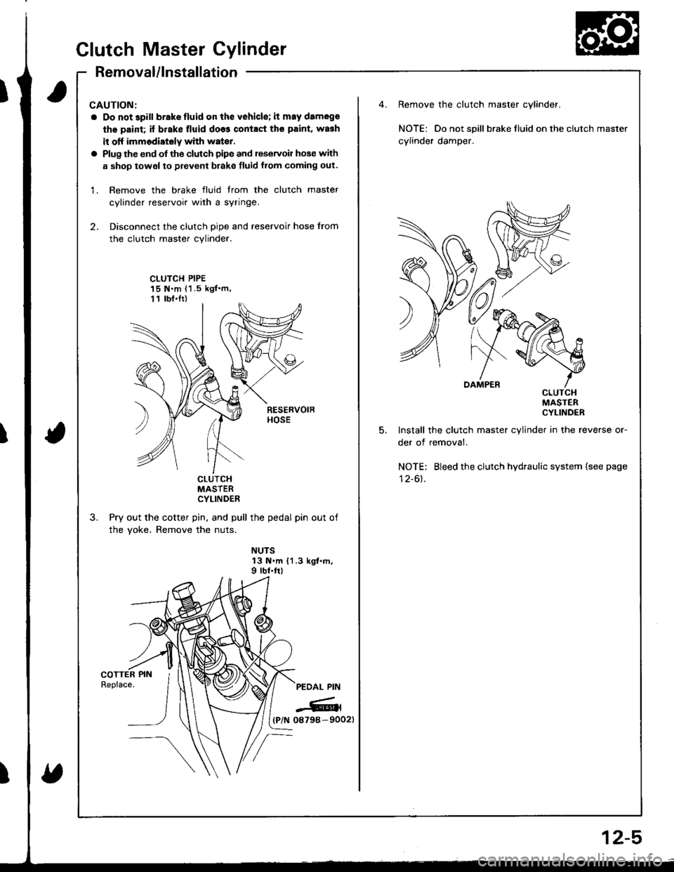
CAUTION:
a Do not 3pill brakefluid on the vehicle; it may damege
th€ paid; if brake fluid do63 contact th€ paint. wa3h
it otf immediately with water.
a Plug the end of the clutch pipe and reservoir hose with
a shop towel to prevent brake fluid from coming out.
1. Remove the brake fluid trom the clutch master
cylinder reservoir with a syringe,
2. Disconnect the clutch pipe and reservoir hose from
the clutch master cylinder.
Remove the clutch master cylinder.
NOTE: Do not spill braketluid ontheclutch master
cylinder damper.
CLUTCH PIPE15 N.m {1 .5 kgf'm,11 lbt.Ir)
5.
cLulcHMASTERCYLINDER
Install the clutch master cylinder in the reverse or-
der of removal.
NOTE: Bleed the clutch hydraulic system {see page
I z-ol.cturcHMASTERCYLINDER
Pry out the cotter pin, and pull the pedal pin out of
the yoke. Remove the nuts.
NUTS13 N.m {1.3 kgt.m,9 rbf.ftl
PEOAL PIN
-6rl(P/N 08798-90021
Clutch Master Cylinder
Removal/lnstallation
2-5
Page 363 of 1681
T
fi
;ill
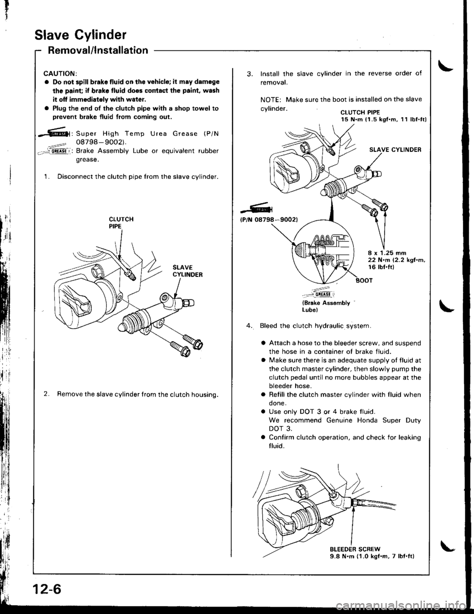
Slave Cylinder
Removal/lnstallation
CAUTION:
a Do not spill brakelluid onthe vehicle; it may dameg€
the paint; if brake fluid does coniaqt the paint, wash
it otf immodiaioly wilh w8ter.
a Plug the end of the clutch pipe with a shop towel to
prevent brake fluid from coming out.
-6|1, Super High Temp Urea Grease (P/N
4==? 08798- 9OO2).-='aii^5Fi: Brake Assembly Lube or equivalent rubber
grease.
1. Disconnect the clutch pipe from the slave cylinder.
2. Remove the slave cylinder from the clutch housing.
12-6
-Gl
lP/N 08798
Install the slave cylinder in the reverse order of
removal.
NOTE: Make sure the boot is installed on the slave
.wlin.larCLUTCH PIPE15 N.m 11.5 kgt.m, 11 lbf.ttl
SLAVE CYLINDER
*9002t
I x 1.25 rnm22 N.m 12.2 kgl.m,16 lbl.lt)
.'....-..-:::-9!!!!!i
{Brake Assembly '
Lube)
Bleed the clutch hydraulic system.
a Attach a hose to the bleeder screw, and suspend
the hose in a container ot brake fluid.
a lvlake sure there is an adequate supply ot fluid at
the clutch master cylinder, then slowly pump the
clutch pedal until no more bubbles appear at the
bleeder hose.
a Refill the clutch master cylinder with fluid when
done.
a Use only DOT 3 or 4 brake tluid.
We recommend Genuine Honda Super Duty
DOT 3.
a Confirm clutch operation. and check for leaking
fluid.
Page 364 of 1681
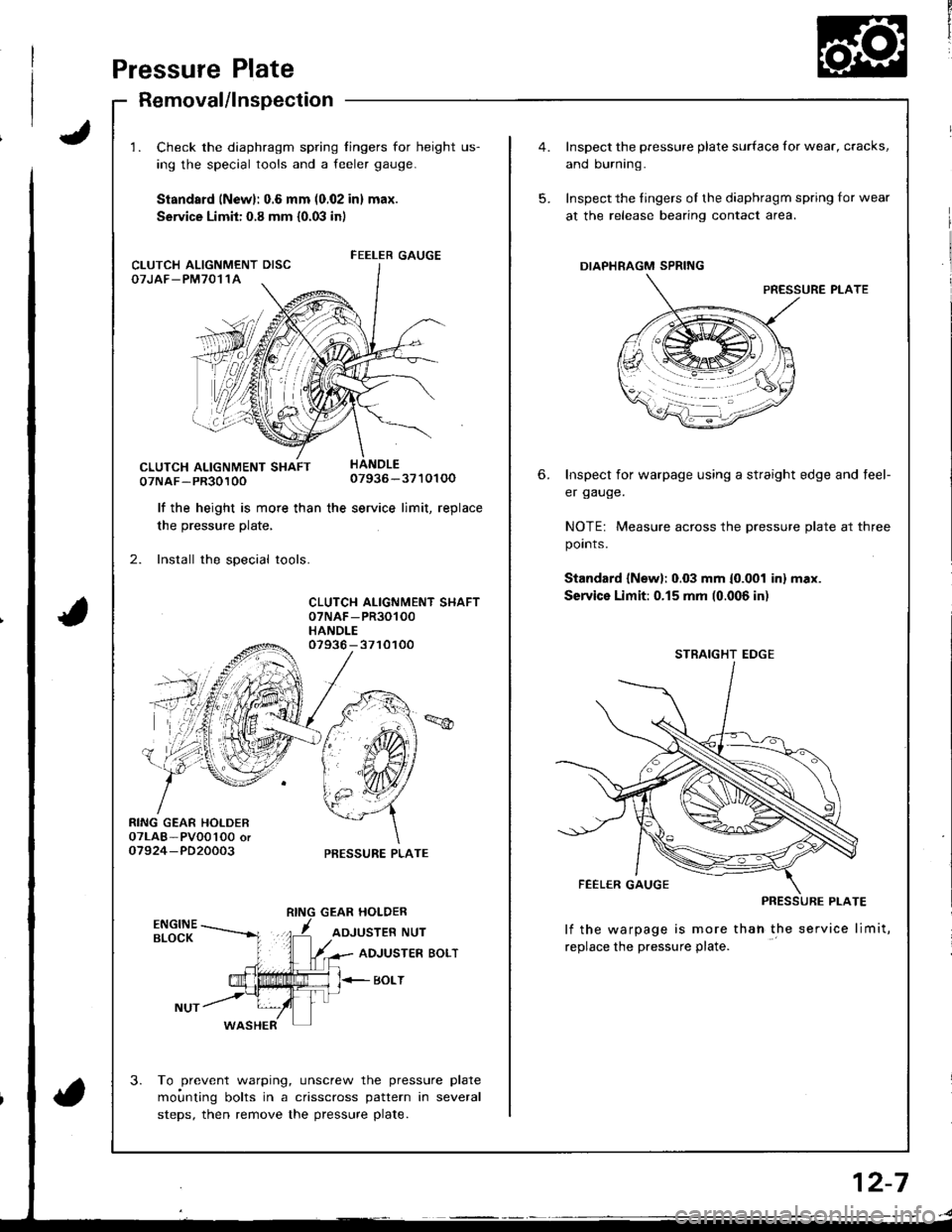
Pressure Plate
Removal/lnspectaon
1. Check the diaphragm spring fingers for height us-
ing the special tools and a feeler gauge.
Standsrd (New): 0.6 mm (0.02 in) max.
Service Limit: 0.8 mm {0.03 in)
07NAF-PR3010007936-3710100
lf the height is more than the service limit, replacethe hro..rr.a nlefe
2. Install the special tools.
CLUTCH ALIGNMENT SHAFT07NAF -PR30100
HANDLE
RING GEAR HOLDER07LAB- PVOo'l0O oro7924-PD20003
07936 - 3710100
PRESSURE PLATE
GEAR HOLDER
ADJUSTER NUT
3.
ADJUSTER BOLT
BOLT
WASHER
To prevent warping, unscrew the pressure plate
moi.rnting bolts in a crisscross pattern in several
steps, then remove the pressure plate.
FEELER GAUGECLUTCH ALIGNMENT DISCOTJAF_PM7011A
5.
6.
Inspect the pressure plate surface for wear, cracks,
and burning.
Inspect the fingers of the diaphragm spring for wear
at the release bearing contact area.
DIAPHRAGM SPRING
PRESSURE PLATE
Inspect for warpage using a straight edge and teel-
er gauge.
NOTE: Measure across the pressure plate at three
points.
Standard {New}: 0.03 mm {0.001 inl max.
Service Limit:0.15 mm (0.006 in)
lf the warpage is more thah the service limit,
replace the pressure plate.
STRAIGHT EDGE
2-7
Page 365 of 1681
rtr
1
Clutch Disc
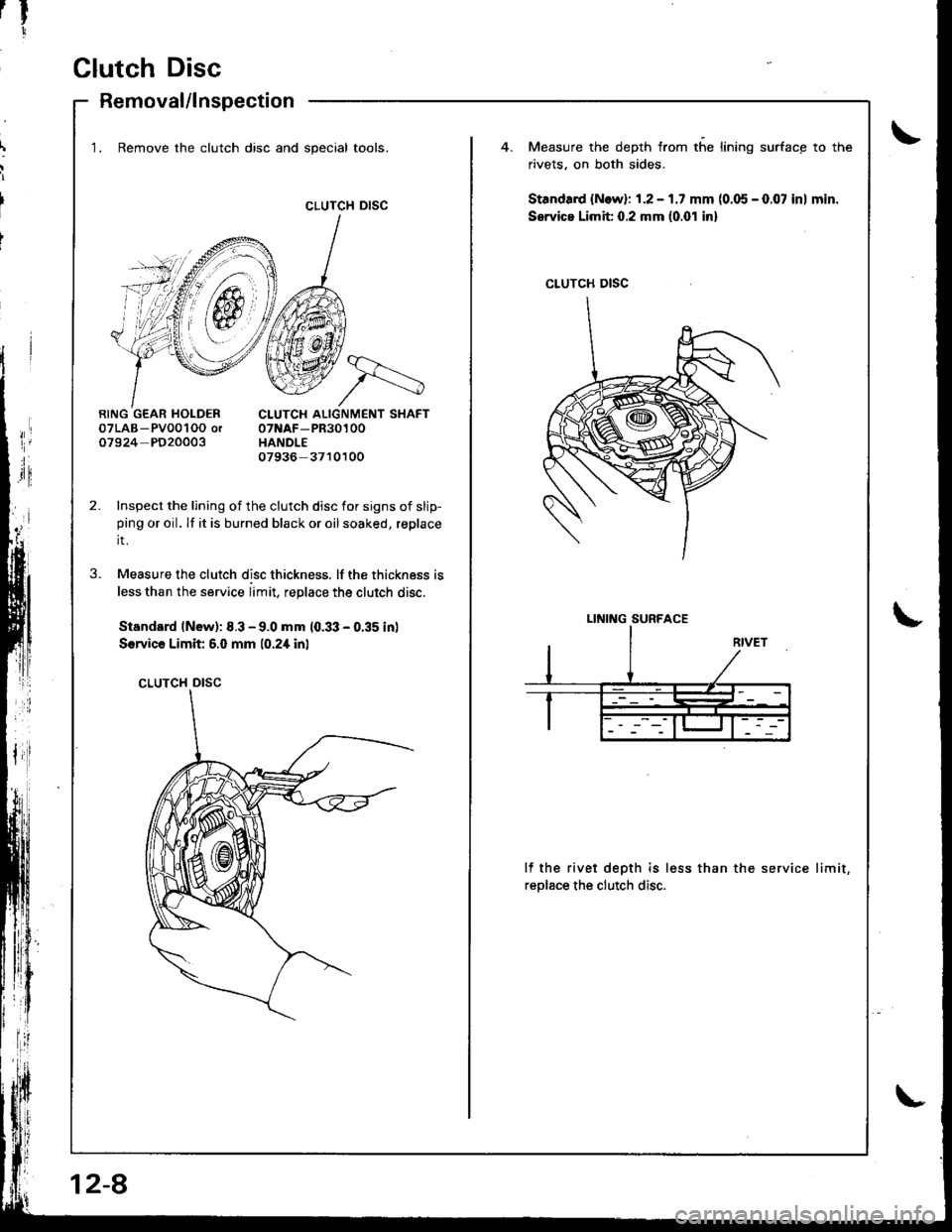
Removal/lnspection
CLUTCH DISC
1. Remove the clutch disc and special tools.Measure the depth from the lining surface to the
rivets. on both sides.
Standa.d {N.w}: 1.2 - 1.7 mm (0.05 - 0.07 in} min.
Service Limit 0.2 mm (0.01 inl
07LAB- Pv001OO or07924 PD20003
CLUTCH ALIGNMENT SHAFT07NAF-PR30100HANDLE07936- 3710100
Inspect the lining of the clutch disc for signs of slip-ping or oil. lf it is burned black or oil soaked, replace
it.
Measure the clutch disc thickness. lf the thickness is
less than the service limit, replace the clutch disc.
Standard lNew): 8.3 - 9.0 mm 10.33 - 0.35 in)
Sorvica Limit 6.0 mm 10.2i[ inl
CLUTCH DISC
3.
lf the rivet depth is less than the service limit,
reolace the clutch disc.
CLUTCH DISC
LINING SURFACE
12-8
Page 366 of 1681
Flywheel, Flywheel Bearing
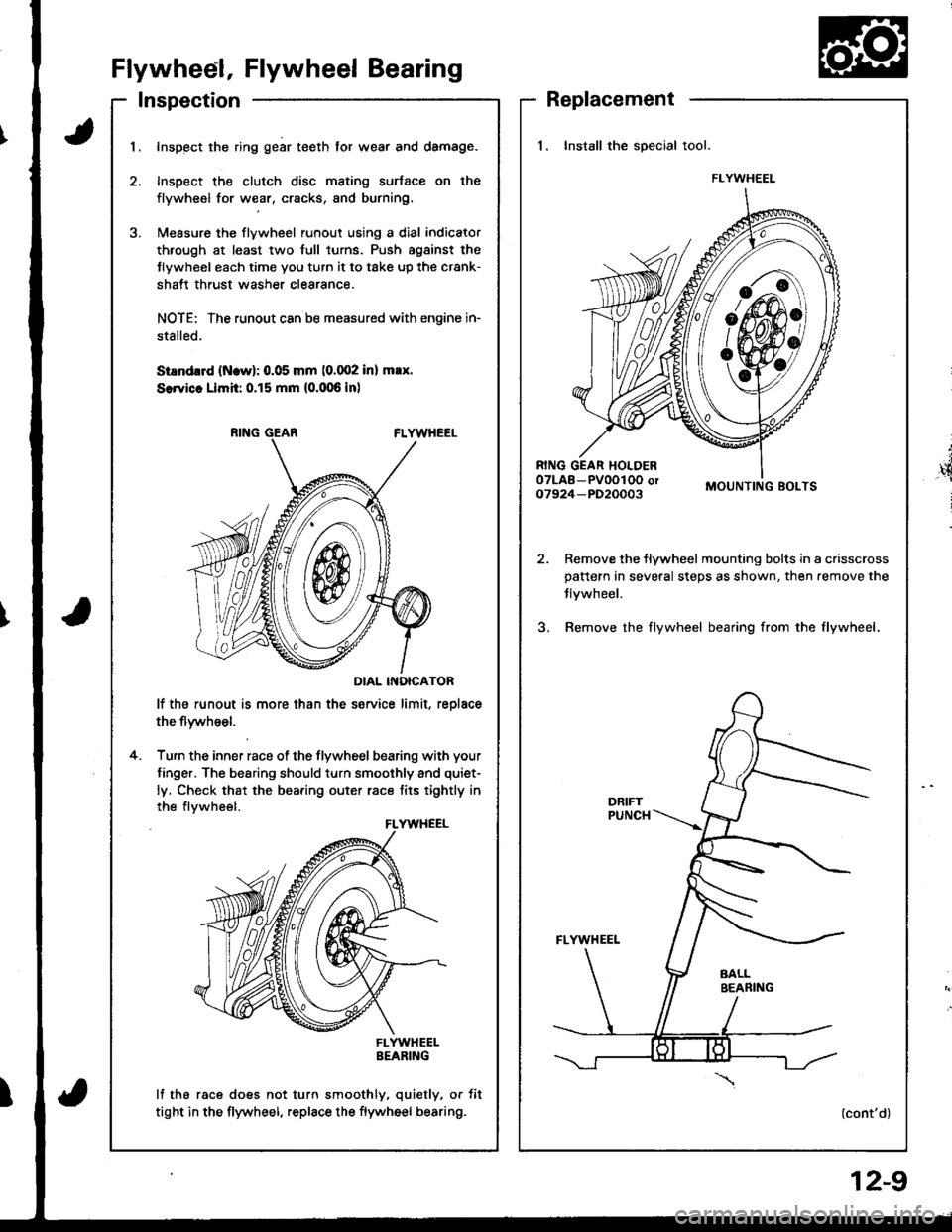
Inspection
t
',4
i
Replacement
1. Install the special tool.
MOUNTING BOLTS
Remove the flywheel mounting bolts in a crisscrosspattern in several steps as shown, then.emove the
Jlvwheel.
Bemove the flywheel bearing from the flywheel.
(cont'd)
FLYWHEEL
I
1.Inspect the ring gear teeth tor wear and damage.
Inspect the clutch disc mating surtace on the
flywheel for wear, cracks, and burning.
l\,reasure the flywheel runout using a dial indicator
through at least two full turns. Push agsinst the
Jlywheel each time you turn it to take up the crank-
shatt thrust washer clearance.
NOTE: The runout can ba measured with engine in-
stalled.
SiEndrrd (Ncw): 0.05 mm (0.002 inl max.
SerYicc Llmh: 0.15 mm (0.006 inl
DIAL INOICATOR
lf the runout is more than the service limit, reolace
the flywheel.
Turn the inner race of the flywheel bearing with your
tinger. The bearing should turn smoothly and quiet-
ly. Check that the bearing outer race tits tightly in
the flvwheel.
FLYWHEELBEARING
lf the race does not turn smoothly, quietly, or tit
tight in the flywheel, replace the flywheel bearing.
4.
FLYWHEEL
12-9
Page 367 of 1681
Clutch Disc,
Flywheel, Flywheel BearingPressure Plate
Replacement (cont'd)Installation
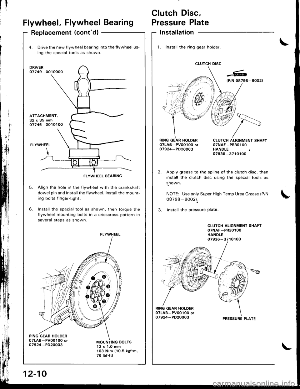
1. Install the ring gear holder.
CLUTCH DISC
1tti
CLUTCH ALIGNMENT SHAFT07NAF-PR30100HANDLE07936 -3710100
Apply grease to the spline ot the clutch disc, then
install the clutch disc using the special tools as
shown.
NOTE: Use only Super High Temp Urea Grease (P/N
o8798 9002).
3. Insrall the pressure Plate.
CLUTCH ALIGNMENT SHAFT07NAF-PR30100HANDLE07936-3710100
RING GEAR HOI-DER07LAB - PV001O0 or07924-PD20003
4. Drive the new flywheel bearing into the flywheel us-
ing the special tools as shown.
DRIVER07749 -0010000
FLYWHEEL
Align the hole in the llywheel with the crankshalt
dowel pin and installthe flywheel. Installthe mount-
ing bolts fingertight.
Install the special tool as shown, then torque the
flvwheel mounting bolts in a crisscross pattern in
several steps as shown-
6.
ATTACHMENT,32x35mm07746 0010100
5.
RING GEAE HOLDER07LAB-Pv00100 or07924-PD20003MOUNTING BOLTS12 x 1.0 mm103 N.m (10.5 kgf .m,
76 tbt.frl
FLYWHEEL BEARING
FLYWHEEL
6!-o
&#,oit
12-10
PRESSURE PLATE
Page 368 of 1681
Release Bearing
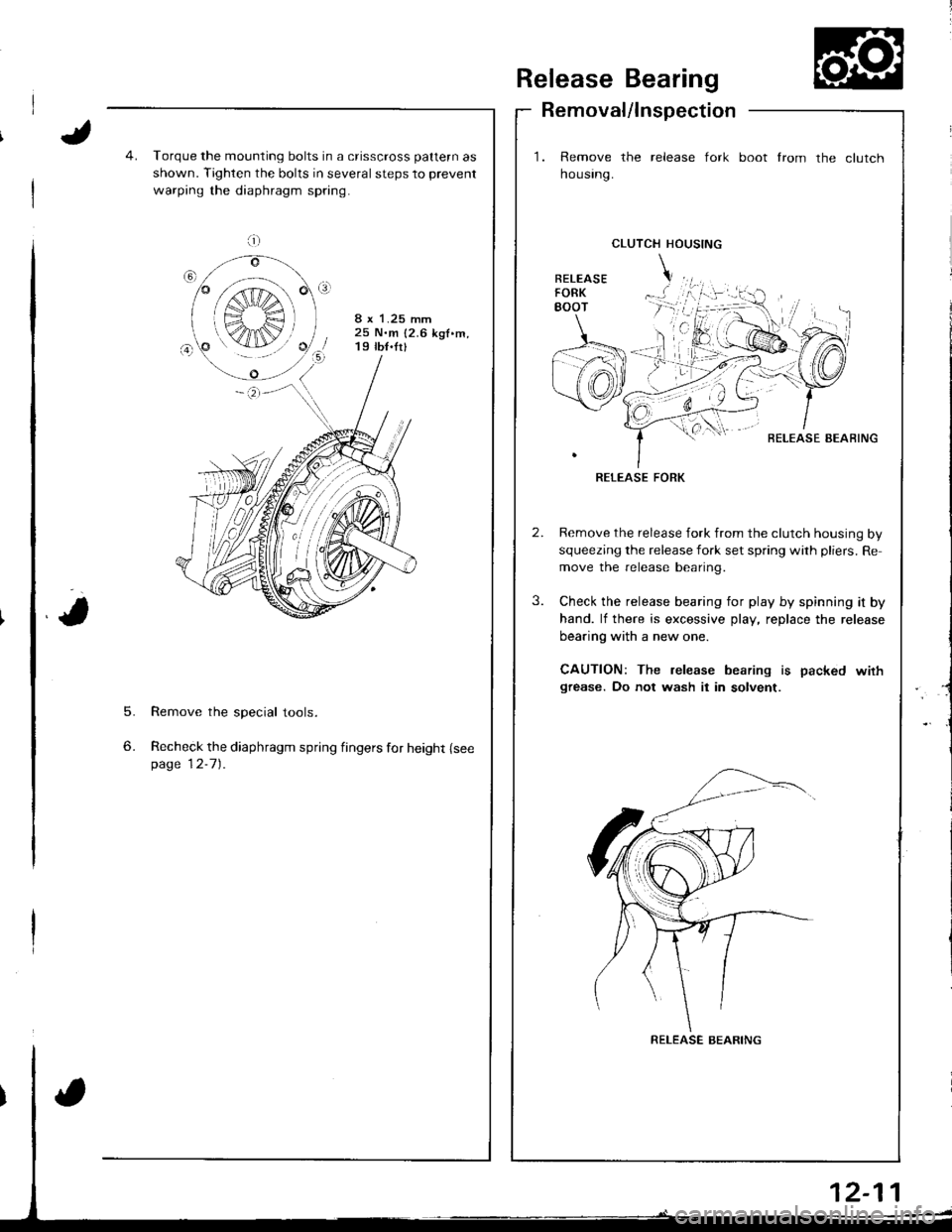
Removal/lnspection
1. Remove the release fork
housrng.
boot from the clutch
5.
6.
Torque the mounting bolts in a crisscross pattern as
shown. Tighten the bolts in several steps to prevent
warping the diaphragm spring.
8 x 1.25 mm25 N.m {2.6 kgf.m,19 tb{.fr}
Remove the special tools.
Recheck the diaphragm spring fingers for height {seepage 12-7).
CLUTCH HOUSING
BELEASE AEAFING
RELEASE FORK
Remove the release fork from the clutch housing by
squeezing the release fork set spring with pliers. Re
move the release bearing.
Check the release bearing for play by spinning it by
hand. lf there is excessive play, replace the release
bearing with a new one.
CAUTION: The release bearing is packed wirhgrease. Do not wash it in solvent.
a;;;:
S",€ r
K4IN/
RELEASE BEARING
Page 369 of 1681
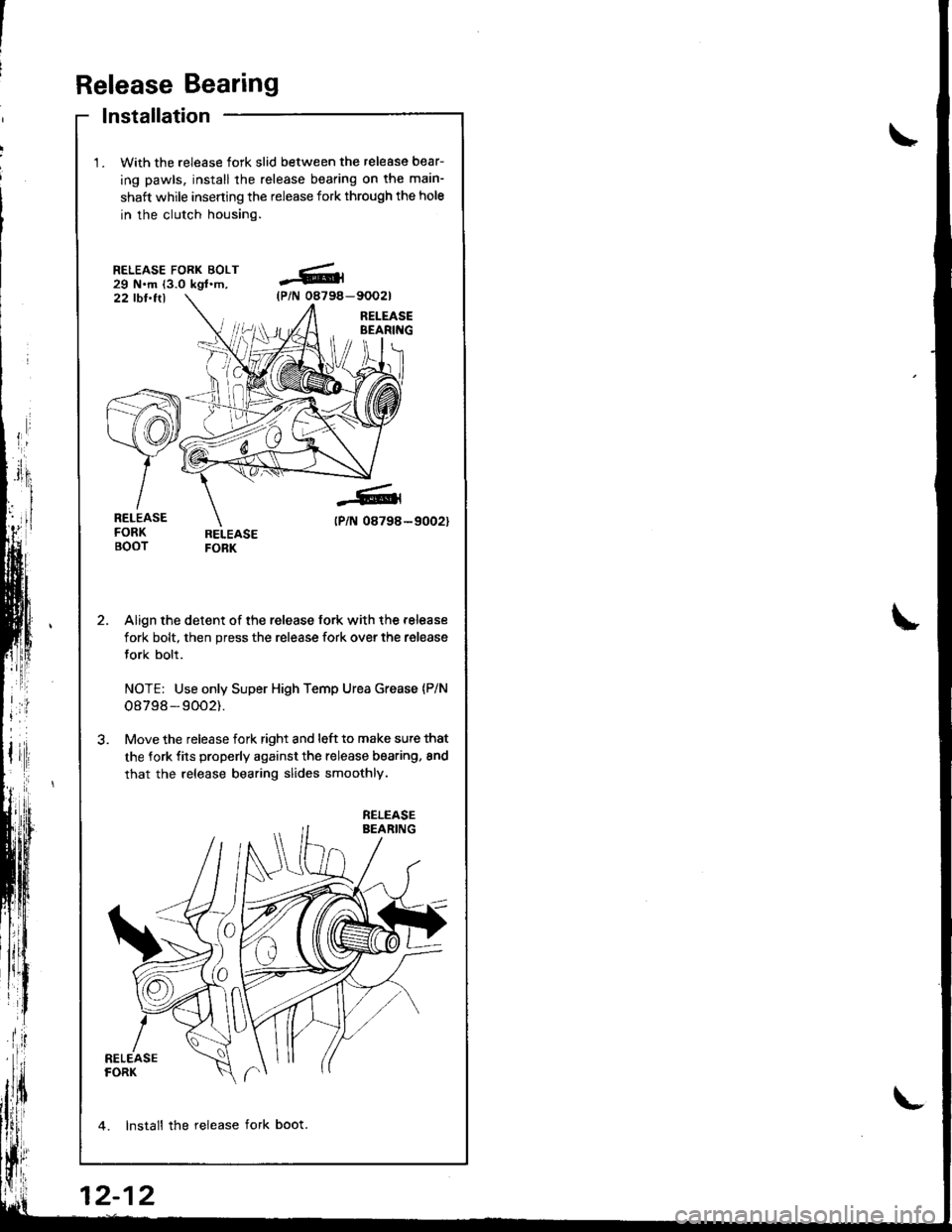
Release Bearing
lnstallation
With the release fork slid between the release bear-
ing pawls, install the release bearing on tha main-
shaft while inserting the release fork through the hole
in the clutch housing.
RELEASE FORK BOLT29 N.m (3.0 kgl.m,22 tbt.ttl
Align the detent of the release fork with the release
fork bolt, then press the release fork over the release
fork bolt.
NOTE: Use only Super High Temp Urea Grease {P/N
o8798 - 9002).
Move the release fork right and l6ft to make sute that
the fork fits properly against the release bearing, 8nd
that the release bearing slides smoothly.
4. lnstall the release fork boot.
-6(P/N 08794-
-6
tPlN 08798-
RELEASE
12-12
Page 370 of 1681
Manual Transmission
Special Tools ............. 13-2
Maintenance
Transmission Oil .............................. 13-3
Back-up Light Switch
Replacement ......... 13-3
Transmission Assembly
Removal ................. 13-4
lllustrated Index ................................... 13-8
Transmission Housing
Removal ................. 13-10
Peverse Change Holder, Reverse ldler Gear
jGlearance Inspection ....................... 13-1 1
Removal ................. 13-12
Change Holder Assembly
Clearance Inspection .....,.,....,,.....,,.. 13-13
Removal ................. 13-15
Disassembly/Reassembly ............... 13-16
Mainshaft, Countershaft, Shift Fork
Removal ................. 13-17
Shift Rod
Removal ................. 13-18
Shift Fork Assembly
Index ................ ...... 13-19
Clearance lnspection ...................,.,. 13-20
Mainshaft Assembly
fndex ................ ......13-21
Clearance f nspection ..,,,.................. 13-22
Disassembly .......... 13-25
Inspection .............. 13-26
Reassembly ........... 13-21
Countershaft Assembly
Index ................ ...... 13-28
Clearance Inspection ....................... 13-29
Disassembly .......... 13-30
Inspestion .............. 13-31
Reassembly ........... 13-32
Synchro Sleeve, Synchro Hub
Inspection .............. 13-34
Installation ............. 13-34
Synchro Ring, Gear
Inspection .............. 13-35
Clutch Housing Bearing
Replacement ......... 13-36
Mainshaft Thrust Clearance
Adiustment ............ 13-38
Transmission
Reassembly ........... 13-41
Transmission Assembly
Installation ............. 13-46
Gearshift Mechanism
Overhaul ................ 13-51