HONDA INTEGRA 1998 4.G Workshop Manual
Manufacturer: HONDA, Model Year: 1998, Model line: INTEGRA, Model: HONDA INTEGRA 1998 4.GPages: 1681, PDF Size: 54.22 MB
Page 341 of 1681
I
lntake
lntake
Air System
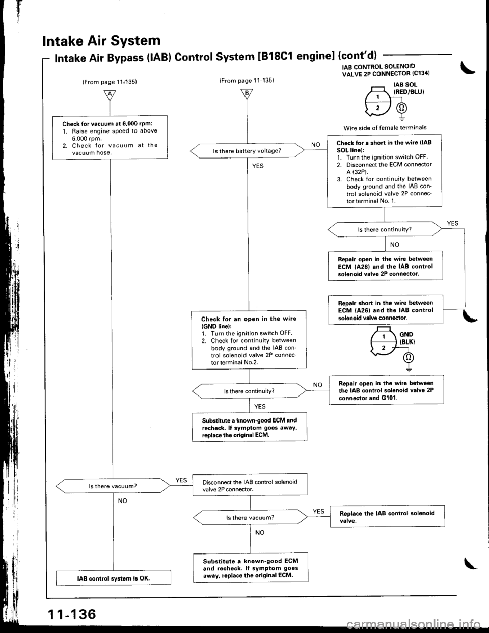
Air Bypass (lABl ControlSystem tB18C1 enginel (cont'd)
(From page 11i135)(From page 11 135)
IAB CONTROL SOLENOID
VALVE 2P CONNECTOR (C13ir)
'._r taB sol-H, IRED/ALUI// 1 \-'lf---:----l /A\
\2Y
Wire side o{ female terminals
\
.t
Check {or vacuum at 6,000 rpm:
1, Raise engane speed to above
6,000 rpm.2. Check for vacuum at the
vacuum hose,
Disconnect the IAB control solenoidvalve 2P connector.ls there vacuum?
Substitute a known-good ECM
and recheck. lf symptom goes
away, replace the original ECM.IAB control svstom is OK.
Check lor a shon in the wire (lAB
SOL line):1. Turn the ignition switch OFF.2. Disconnect the ECM connector
A (32P).
3. Check for continuity betweenbody ground and the IAB con'
trol solenoid valve 2P connec-
torterminalNo. 1.
ls there battery voltage?
Repair open in the wire betwaonECM lA26) and the IAB controlsolenoid valve 2P connectoa.
Check tor an open in the wiro
{GND line)r1. Turn the ignition switch OFF.2. Check for continuity betweenbody ground and the IAB con-
trol solenoid valve 2P connector terminal No.2.
Repair open in the wire betweenthe IAB control solenoid valve 2Pconnector and G101.
Subdhnte a known-good ECM andrecheck. ll symptom goes away,r€place the original ECM.
\
Page 342 of 1681
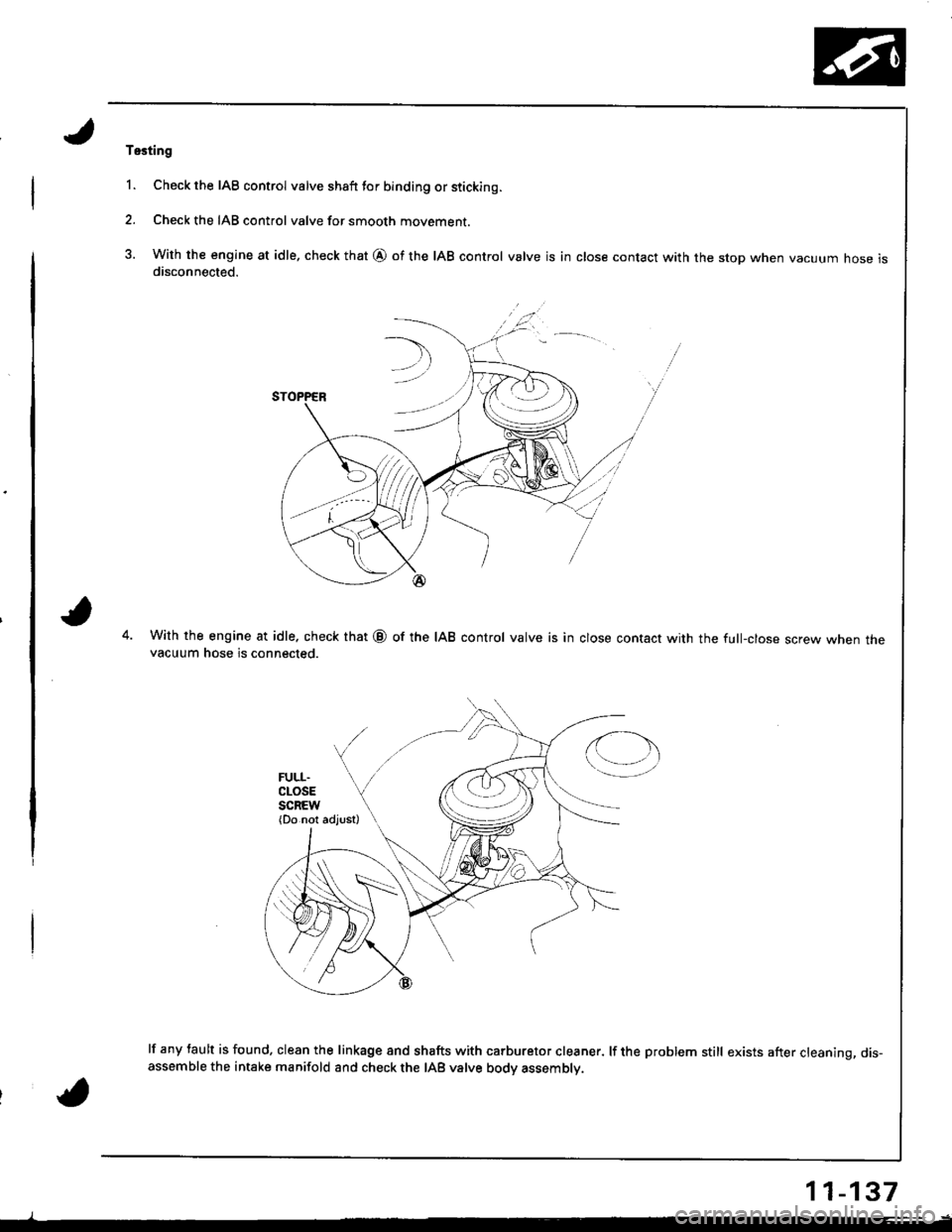
Tssting
1. Check the IAB control valve shaft tor binding or sticking.
2. Check the IAB control valve for smooth movement.
3. With the engine at idle, check that @ of the IAB control valve is in close contact with the stop when vacuum hose isdisconnected.
With the engine at idle. check that @ of the IAB control valve is in close contact with the full-close screw when thevacuum hose is connected.
lf any tault is found, clean the linkage 8nd shafts with carburetor cleaner. lf the problem still exists after cleaning, dis-assemble the intake manifold and check the IAB valve body assembly.
11-137
Page 343 of 1681
t"iI
Emission Gontrol System
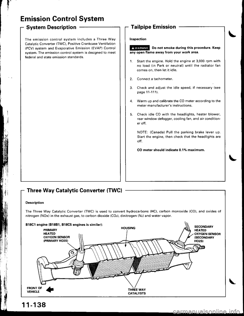
System Description
Three Way Catalytic Converter (TWCI
\
t
The emission control system includes a Three Way
Catalytic Converter (TWC), Positive Crankcase Ventilation
(PCV) system and Evaporative Emission (EVAP) Control
system. The emission control system is designed to meet
tederal and state emission standards.
InsDeciion
!@@ Do not smoke during this procedure. Keep
any open llame away from your work area.
1. Start the engine. Hold the engine at 3,000 rpm with
no load {in Park or neutral) until the radiator fan
comes on, then let it idle.
2. Connect a tachometer.
Check and adjust the idle speed, if necessary (see
page '11-11 ! ).
Warm up and calibrate the CO meter according to the
meter manufacturer's instructions.
Check idle CO with rhe headlights, heater blower,
rear window defogger, cooling fan, and air condition-
er off.
NOTE: {Canada) Pull the parking brake lever up.
Start the engine, then check that the headlights are
olf.
CO meter should indicste 0.17o maximum.
DescriDtion
The Three Way Catalytic Converter {TWC) is used to convert hydrocarbons (HC), carbon monoxide (CO), and oxides of
nitrogen (NOx) in the exhaust gas, to carbon dioxide (COr), dinitrogen {Nr) and water vapor.
Bl8Cl engine l818Bl, 818C5 engines is similar):
FRONT OFVEHICLE
PRIMAEYHEATEDOXYGEN SENSORIPRIMARY HO2S}
HOUSING
WAYCATALYSTS
SECONOARYHEATEDOXYGEN SENSOR{SECONDARYH02St
\
Page 344 of 1681
Three Way Catalytic Converter (TWC)
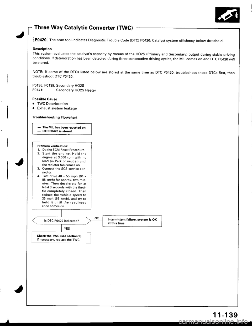
lT042O I Th" """n tool indicates Diagnostic Trouble Code (DTC) P0420: catatyst system efficiency below threshold.
Descriotion
This system evaluates the catalyst's capacity by means of the HO2S (Primary and Secondary) output during stable drivingconditions. lf deterioration has been detected during three consecutive driving cycles, the MIL comes on and DTC p0420 willbe stored.
NOTE: lf some of the DTCS listed below are stored at the same time as DTC PO42O. troubleshoot those DTCS tirst. thentroubleshoot DTC P0420.
P0136, P0139: Secondarv HO2S
P0141:Secondary HO2S Heater
Possible Cause
. TWC Deterioration
. Exhaust system leakage
Troubleshooting Flowchart
Problem verification:1. Do the ECM Reset Procedure.2. Start the engine. Hold theengine at 3,000 rpm with noload (in Park or neutral) untilthe radiator fan comes on,3. Connect the SCS service con,
4. Test drive 40 - 55 mph (64 -
88 km/h) for approx. two min-utes, Then decelerate Ior atleast 3 seconds with the throttle completely closed. Thenreduce the vehicle speed to35 mph (56 km/h), and try tohold it until the readinesscode comes on.
I
- The MIL has been report€d on.- OTC P0420 is stored.
Intermittent tailure, sFtem is OKat this time.ls DTC P0420 indicated?
Check the TWC {s6e 3ection 91.lf necessary, reolace the TWC.
11-139
Page 345 of 1681
'il
Emission Gontrol System
Positive Crankcase Ventilation (PCV) System
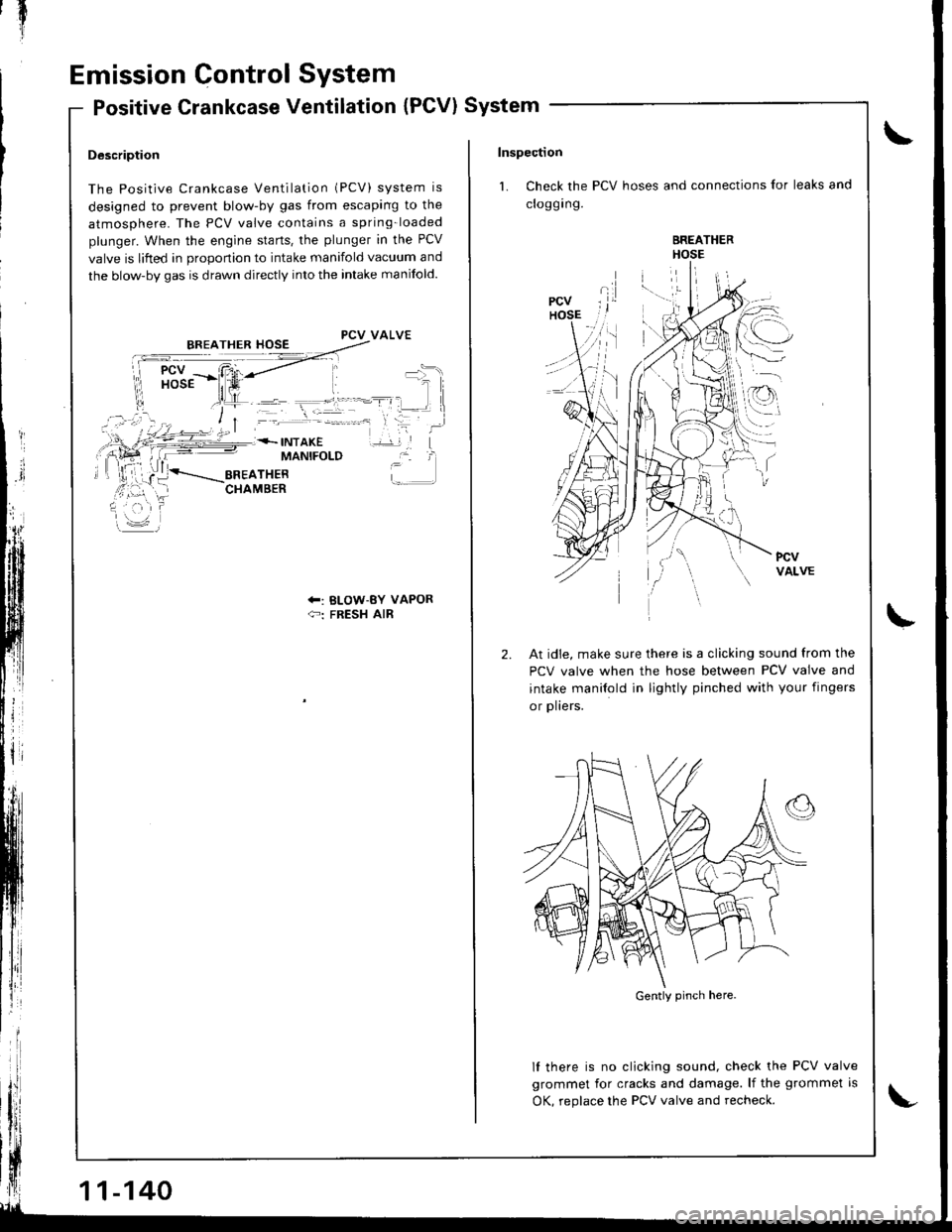
Description
The Positive Crankcase Ventilation (PCV) system is
designed to prevent blow-by gas from escaping to the
atmosphere. The PCV valve contains a spring-loaded
plunger. When the engine starts. the plunger in the PCV
valve is lifted in orooonion to intake manifold vacuum and
the blow-by gas is drawn directly into the intake manifold.
PCV VALVE
MANIFOLD
+: BLOW-BY VAPOR{-: FRESH AIR
11-140
Inspection
1. Check the PCV hoses and connections for leaks and
croggrng.
BREATHERHOSE
l.--:\
,.r
I
2.At idie, make sure there is a clicking sound from the
PCV valve when the hose between PCV valve and
intake manilold in lightly pinched with your fingers
or plters.
lf there is no clicking sound, check the PCV valve
grommet for cracks and damage. lf the grommet is
OK, reolace the PCV valve and recheck.
Gently pinch here.
Page 346 of 1681
Evaporative Emission (EVAP) Controls
,J
a
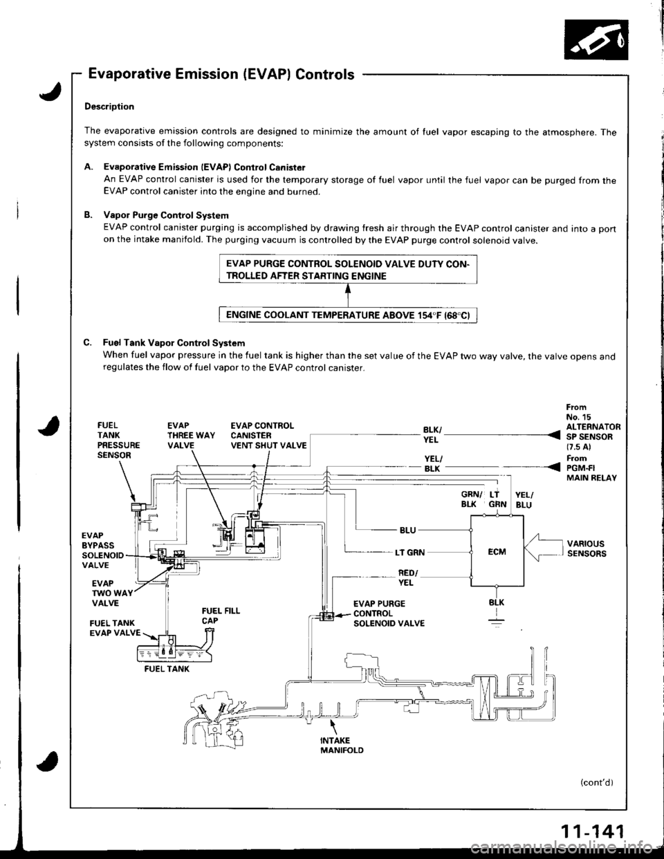
DescriDtion
The evaporative emission controls are designed to minimize the amount of luel vapor escaping to the atmosphere. Thesystem consists of the following components:
A. EvaporativeEmission lEVAPlControlCanister
An EVAP control canister is used for the temporary storage of fuel vapor until the fuel vapor can be purged from theEVAP control canister into the engine and burned.
B. Vapol Purge Control System
EVAP control canister purging is accomplished by drawing fresh air through the EVAP control canister and into a pon
on the intake manifold. The purging vacuum is controlled by the EVAP purge control solenoid valve.
C. Fuel Tank Vapor Control System
When fuel vapor pressure in the fuel tank is higher than the set value of the EVAP two way valve, the varve opens anoregulates the flow of fuel vapor to the EVAP control canister.
FrcmNo. 15FUELTANKPRESSURESENSOR
EVAPTHREE WAYVALVE
EVAP CONTROLCANISTENVENT SHUT VALVE
YEL/- BLK
EVAPBYPASSSOLENOIDVALVE
LT GRN
RED/EVAPTWO WAYVALVE
FUEL TANKEVAP VALVE
FUEL TANK
EVAP PURGE CONTROL SOLENOID VALVE DUTY CON-
TROLLED AFTER STARTING ENGINE
?!l ---- 311'AiS-*(7.s Al
FromPGM.FIMAIN RELAY
VARIOUSSENSORS
----<
YEL
EVAP PURGECONTROLSOLENOID VALVE
(cont'd)
-141
Page 347 of 1681
lT
Emission Control System
YES
{To page 11-143}
Fu€l Tank Pressure Sensor
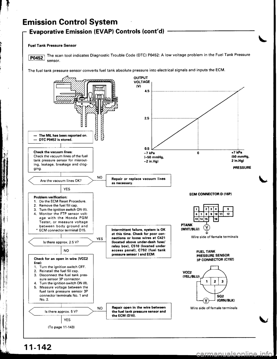
The scan tool indicates Diagnostic Trouble Code (DTC) P0452: A low voltage problem in the Fuel Tank Pressure
sensor.
The fuel tank pressure sensor converts tuel tank absolute pressure into electrical signals and inputs the ECM.
Evaporative Emission (EVAP) Controls (cont'dl
OUTPUTVOLTAGE(vl
4.5
0.5-7 kPel-50 mmHg,-2 in.Hgl
+7 lPe
l5o mmHg,2 in.Hgl
PRESSURE
\*
Eclrl CONNECToR o {lEPl
PTANK(wltT/BLul
vcc2IYEL/BLU}
Wire side of lemale terminals
FUEL TANKPRESSURE SENSOR
3P CONNECTOR (C792)
The MIL ha3 beon roportod on.OTC F0452 i3 storad.
Chock the vscuum lines:Check the vacuum lines otthe fueltank pressure sensor for misrout-ing, leakage, breakage and clog-ging.
Are the vacuum lines OK?
Problgm verilication:1. Do the ECM Reset Procedure.2. Remove the fuel fill cap.3. Turn the ignition switch ON lll).4. Monitor the FTP sensor volt-age with the Honda PGMTester, or measure voltagebotween body ground and' ECM connector terminal D15.Int6rmittent tailure, 3ystem i3 OKat thb tirn6. Chock lor poor con-n.clions or loo3e wire3 ot C421{locltod rbovo under-d!.h fuso/r.lay boxl, C510 lloc.ted undo.rcc.rs panoll, C?92 Ituel trnko.6sura i€nior I lnd ECM.
ls there approx.2.5 V?
Check to. an opon in wi.a {VCC2line):1. Turn the ignition switch OFF.2. Reinstall the fuel fill cap.3. Disconnect the luel tank pres'su re sensor 3P connector.4. Turnthe ignition switch ON (ll).
5. Measure voltage between thetuel tank pressure sensor 3Pconnector terminals No, 1 andNo.2.
R.pai. opcn in thg wir6 bdtwoonthc fual tank pro$ure 3enlor andtho EcM lDlo).ls there approx. 5 V?
11-142
Wire side oI temale terminals
Page 348 of 1681
{From page 11-142i
Chock lor a short in tho wi.oIPTANK linel:Measure voltage between the fueltank pressure sensor 3P connec-tor terminals No. 2 and No. 3.
ls there approx. 5 V?
Chock for.3hort in th6 wi.e(PTANK lincl:1. Turn the ignition switch OFF.2. Disconnect the ECM connec,tor D (16P).
3. Check lor continuity betweenthe {uel tank pr€sslrre sensor3P connector terfiinal No. 3and body ground.
Ropri. 3hon in tho wira betwaGnthe fuel t.nk prosaura san3or andECM tD15t.
Substituta s known-good ECM.nd recheck. It normel fuel tenkpressure son30r is indicatod,raplacg tho o.iginal ECM.
FUEL TANKPRESSURC SENSOR3P CONNECTOR lc792l
PTANKILT GRN}
sG2IGRN/BLKI
Wire sido of temale terminals
(cont'd)
11-143
Page 349 of 1681
rI
Emission Control System
Evaporative Emission (EVAPI Controls (cont'd)
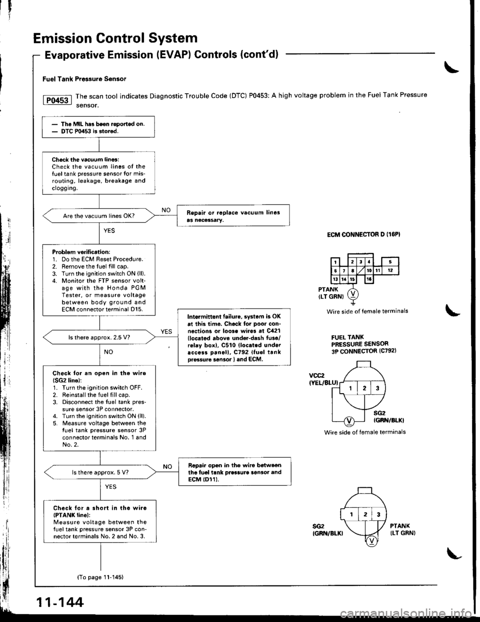
Fuel Tank Pre$ure sensor
The scan tool indicates Diagnostic Trouble Code (DTC) P0453: A high voltage problem in the Fuel Tank Pressure
sensor.
ECM OONNECTOR D IT6PI
PTANKILT GRNI
Wire side of female terminals
FUEL TANKPRESSURE SENSOR3P CONNECTOR {C7921
\
voc2
{YEL/BLU}
sG2IGBN/BI.KI
Wire side of female terminals
The Mll- hes bson.opofiad on.DTC m453 b stored.
Check ihe vacuum lino3:Check the vacuum Iines ot the{uel tank pressure sensor for mis-routing, leakage, breakage andcroggrng.
Are the vacu!m lin€s OK?
Problem vsrification:1. Do the ECM Reset Procedure.2. Remove the fuel fill cap.3. Turn the ignition switch ON {ll).4. Monitor the FTP sensor volt-age with the Honda PGMTester, or measure voltagebetween body ground andECM connector terminal D15.Intormittont failu.e. syst6m is OK
at ihi3 time, Chack for poor con.nections or loo3e wires at C421{locatod abovo undel-dash fu3e/rolay box), C510 (loc.ted undoracc6s3 Dan6ll, C792 Ituol trnkDro.su.6 sen3or l and ECM,
ls there approx. 2.5 V?
Check tor an open in the wire(SG2 lino):1. Turn the ignition switch OFF.2. Reinstall the fuel fill cap.3. Disconnect the fuel tank pres-
sure sensor 3P connector.4. Turn the ignition switch ON {ll}.5. Measure voltage between thetuel tank pressure sensor 3Pconnector terminals No. 1 andNo.2.
Rcpair opon in the wire b6tw66nthe fu6l tank prasSuaa 36n3or endECM {Dr1).ls there approx. 5 V?
Check lor a short in tho wirc{PTANK linel:Measure voltage between thefueltank pressure sensor 3P con-nector terminals No. 2 and No. 3.
YES
sG2IGRN/BLKI
PTANKILT GRNI
{To page 1l-145)
11-144
Page 350 of 1681
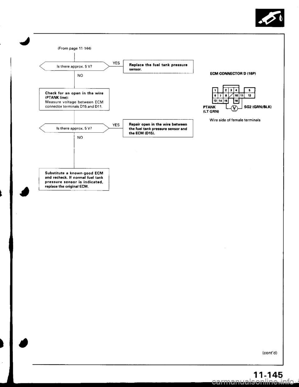
(From page 11 144)
ls there approx. 5 V?
Check foi an opon in th. wi.e{PTANK line}:Measure voltage between ECMconnector terminals D15 and D11.
Ropair opon in the wire betwe€nihe lual tank ore$ure sen3or andthe ECM {D151,
ls there approx.5 V?
Substitute e known-good ECMand racheck. lf normal fuel tankpressure sensor is indicated,replace the original ECM.
ECM OONNECTOR D I16P)
PTANK(LT GRNISG2 IGRN/BLKI
Wire side of female terminals
11-145