HONDA INTEGRA 1998 4.G Workshop Manual
Manufacturer: HONDA, Model Year: 1998, Model line: INTEGRA, Model: HONDA INTEGRA 1998 4.GPages: 1681, PDF Size: 54.22 MB
Page 391 of 1681
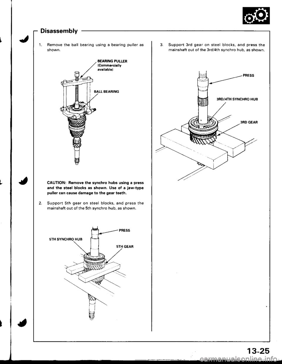
Disassembly
1. Remove the ball bearing using a bearing puller as
shown.
BEARING PULLERlCommerciallyrv.ilable)
BALL BEARING
CAUTION: Remove th€ synchro hubs using a press
and the stsel blocks as shown. Use ot a jaw.type
puller can cause damage to the gear teeth.
Support sth gear on steel blocks, and press the
mainshaft out of the sth synchro hub, as shown.
sTH SYNCHRO HUB
sTH GEAR
3.Support 3rd gear on steel blocks, and press the
mainshaft out of the 3rd/4th synchro hub, as shown.
Page 392 of 1681
I
Mainshaft Assembly
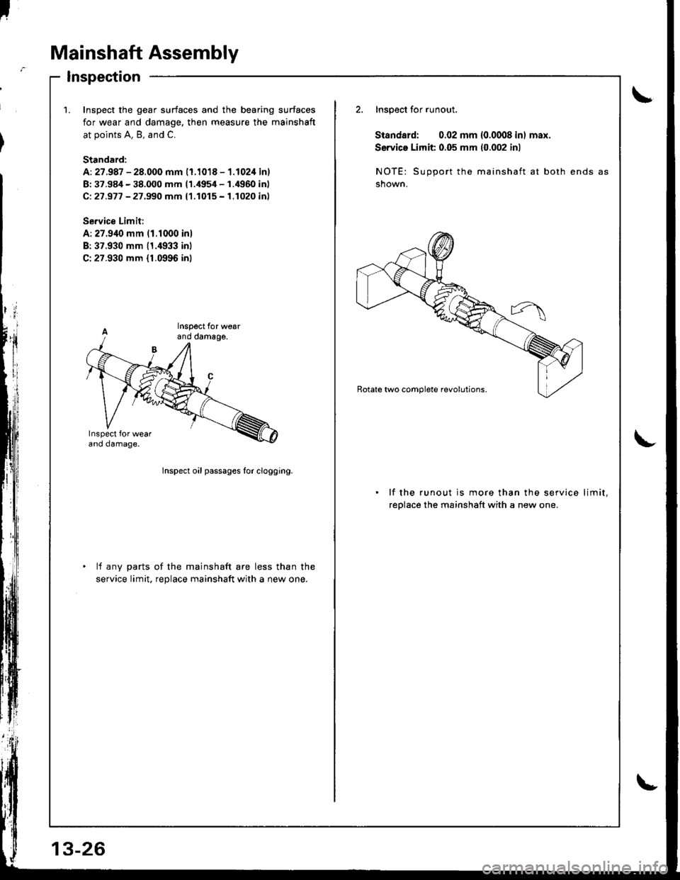
Inspection
\1.Inspoct the gear surfaces and the bearing surfaces
for wear and damage, then measure the mainshaft
at points A. B, and C.
Standard:
A: 27.987 - 28.000 mm (1.1018 - 1.1024 inl
B: 37.984 - 38.000 mm 11.4954 - 1.4960 inl
Ci 27 .977 - 27 .99O mm { 1.1015 - 1.1020 inl
Se.vice Limit:
A: 27.940 mm 11.1000 inl
B:37.930 mm 11.4933 inl
C:27.930 mm {1.0996 inl
2. Inspect for runout.
Standard: 0.02 mm 10.0008 inl max.
Service Limit 0.05 mm (0.002 inl
NOTE: Support the mainshaft at both ends
shown.
lnspect oil passages for clogging.
lf the runout is more than the service limit,
reolace the mainshaft with a new one.
lf any parts of the mainshaft are less than the
service limit, reDlace mainshaft with a new one.
Page 393 of 1681
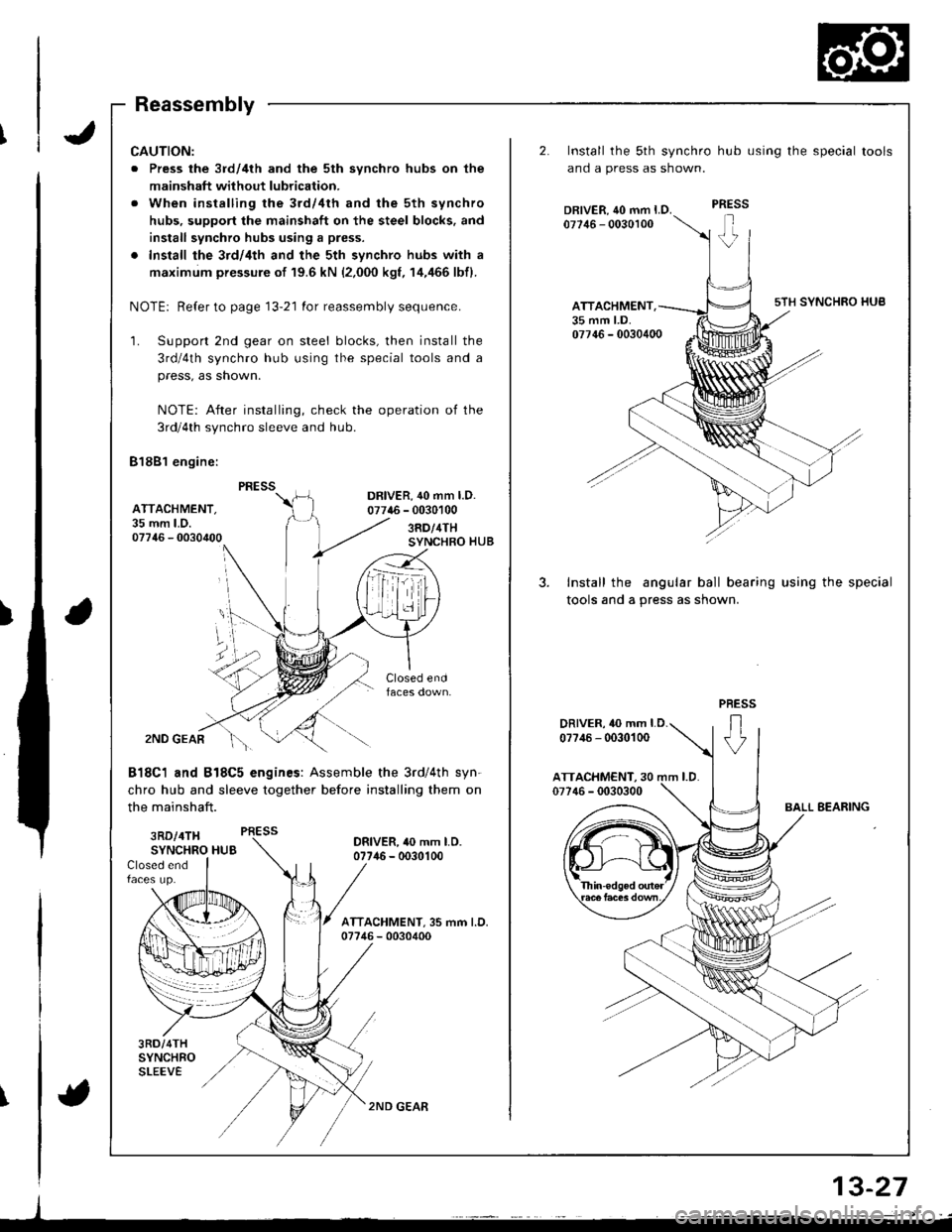
Reassembly
CAUTION:
. Press the 3rd/4th and the 5th synchro hubs on the
mainshaft without lubrication.
. When installing rhe 3rd/4th and the 5th synchro
hubs, support the mainshaft on the steel blocks. and
install synchro hubs using a press.
. Install the 3rd/4th and the 5th synchro hubs with a
maximum pressure of 19.6 kN {2,000 kgf, 14,/166 lbfl.
NOTE: Refer to page 13-21 for reassembly sequence.
'1. Support 2nd gear on steel blocks, then install the
3rd/4th synchro hub using the special tools and a
press, as shown.
NOTE: After installing, check the operation of the
3rd/4th synchro sleeve and hub
81881 engine:
DR|VER,40 mm l.D.07746 - 0030100AITACHMENT.35 mm LD.07746 - 00304003RD/4THSYNCHRO HUB
f
2ND GEAR
818C1 and B18C5 engines: Assemble the 3rd/4th syn-
chro hub and sleeve together before installing them on
the mainshaft.
3RD/4TH PRESS
SYNCHRO HUBORIVER, 40 mm LO.07746 - 0030100Closed endfaces up.
3RD/4THSYNCHROSLEEVE
2ND GEAR
2.
3.
Install the sth synchro hub using the special tools
ano a press as snown.
Install the angular ball bearing using the special
tools and a press as shown.
ATTACHMENT.35 mm LD.
DRIVER, 10 mm LD.
07?,16 - 0030100
J
a
\
13-27
{
Page 394 of 1681
'f
I
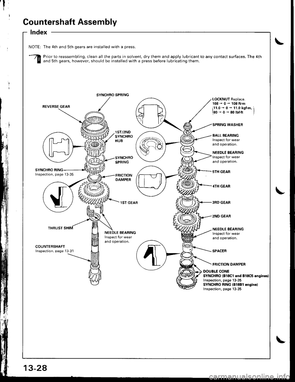
Gountershaft Assembly
Index
\NOTEI
3
The 4th and sth gears are installed with a press.
Prior to reassembling, clean all the parts in solvent, dry them and apply lubricant to any contact surfaces. The 4thand sth gears, however, should be installed with a press before lubricating them.
REVERSE GEAR
THRUST
lST/2NOSYNCHROHUB
SYNCHROSPRING
DAMPER
lST GEAR
LOCKNUT Replace.r08- 0- 108N.m
il1.0 - 0 - 11.0 kgJ.m, \180-0-80rbt.fi /
SPRING WASHEB
BALL BEARING
ano operalron.
NEEDLE BEARINGInspect for wearano operaron,
sTH GEAR
4TH GEAR
3RD GEAB
2NO GEAR
NEEDLE SEARINGInspect for wea.ano opera[|on.
SPACER
FRICTION DAMPER
NEEDLE BEARING
ano operalton,
COUNTERSHAFTInspection, page 13'31
DOUBLE CONESYNCHRO {Bl8Cl snd 818C5 ongines)Inspection. page 13-35SYNCHRO RING (B18Bl 6ngin6lInspection. page 13-35
SYNCHRO SPRING
13-24
Page 395 of 1681
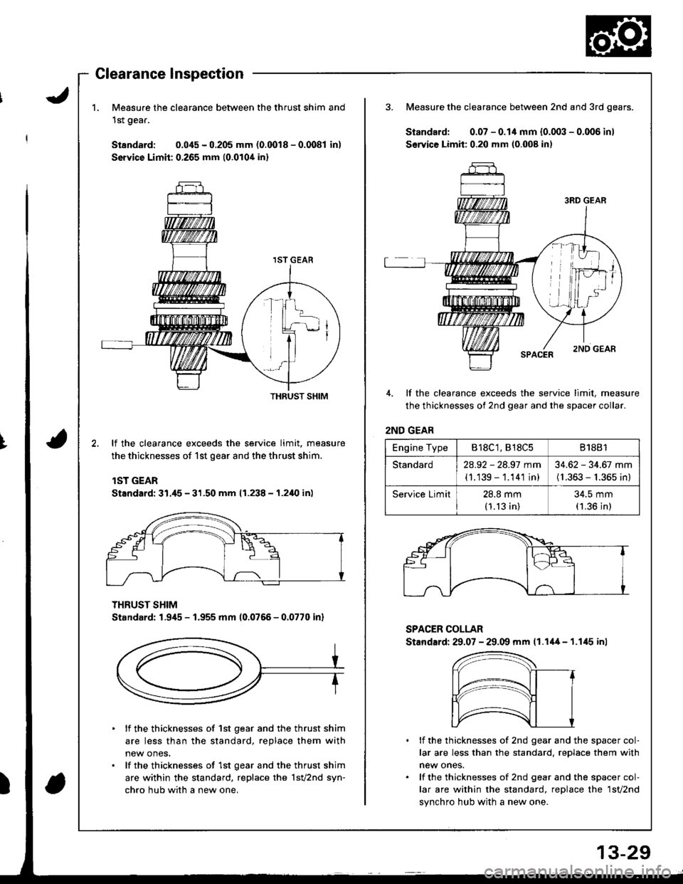
1.Measure the clearance between the thrust shim and
1st gear.
Standard: 0.045 - 0.205 mm (0.0018 - 0.0081 in)
Service Limit:0.265 mm {0.0104 in}
3. Measure the clearance between 2nd and 3rd gears.
Standard: 0.07 - 0.14 mm {0.003 - 0.006 inl
Service Limit: 0.20 mm (0.008 in)
4. lf the clearance exceeds the service limit, measure
the thicknesses of 2nd gear and the spacer collar.
2ND GEAR
lf the clearance exceeds the service limit, measure
the thicknesses of 1st gear and the thrust shim.
lST GEAR
Standard: 31./t5 - 31.50 mm (1.238 - 1.2i10 in)
THRUST SHIM
Standard: 1.945 - 1.955 mm (0.0766 - 0.0770 inl
SPACER COLLAR
Stand.rd: 29.07 - 29.09 mm 11.1'+4 - 1.1,15 inl
lf the thicknesses of 1st gear and the thrust shim
are less than the standard, replace them with
new ones,
lf the thicknesses of 1st gear and the thrust shim
are within the standard, replace the 1sv2nd syn-
chro hub with a new one,
lf the thicknesses of 2nd gear and the spacer col-
lar are less than the standard, reDlace them with
new ones.
lf the thicknesses of 2nd gear and the spacer col-
lar are within the standard, replace the 1sv2nd
synchro hub with a new one.
THRUST SHIM
Engine TypeB18C1, 818C581881
Standard2a.92 - 28.97 mm
(1.139 - 1.141 in)
34.62 - 34.67 mm(1.363 - 1.365 in)
Service Limit28.8 mm(1.13 in)
34.5 mm(1.36 in)
Page 396 of 1681
f-
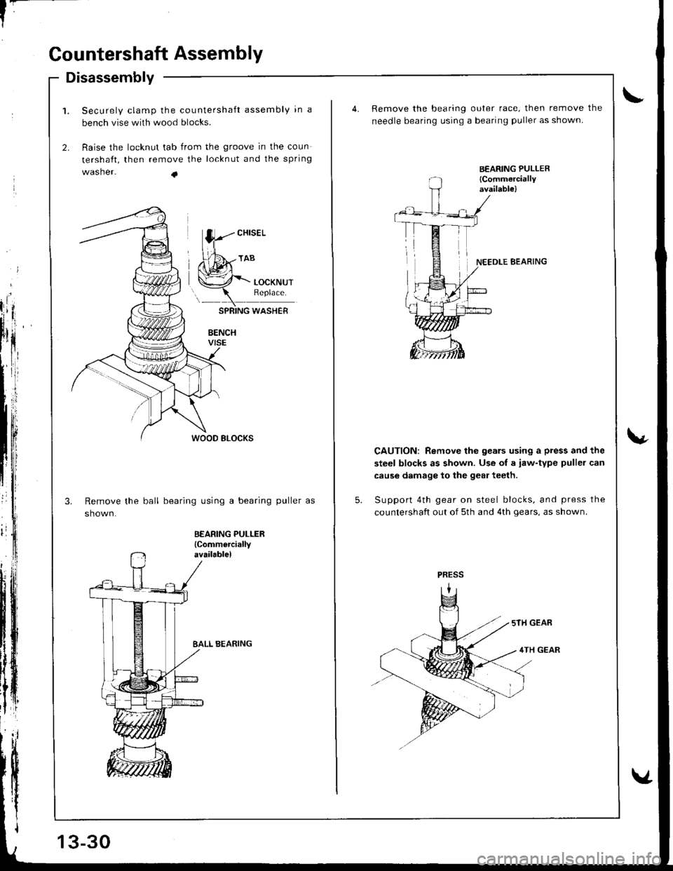
Countershaft Assembly
BEARING PULLER
{Commerciallyavailable)
Disassembly
Securely clamp the countershaft assembly in a
bench vise with wood blocks.
Raise the locknut tab from the groove in the coun
tershaft, then remove the locknLlt and the spring
washer. +
WOOD BLOCKS
Remove the ball bearing using a bearing puller as
shown.
BALL BEARING
13-30
4.Remove the bearing outer race, then remove the
needle bearing using a bearing puller as shown.
,/NEEDLE BEARING
CAUTION: Remove the gears using a press and the
steel blocks as shown. Use oI a iaw-type puller can
cause damage to the geal teeth.
Support 4th gear on steel blocks. and press the
countershaft out of sth and 4th gears, as shown.
4TH GEAR
Page 397 of 1681
I
t
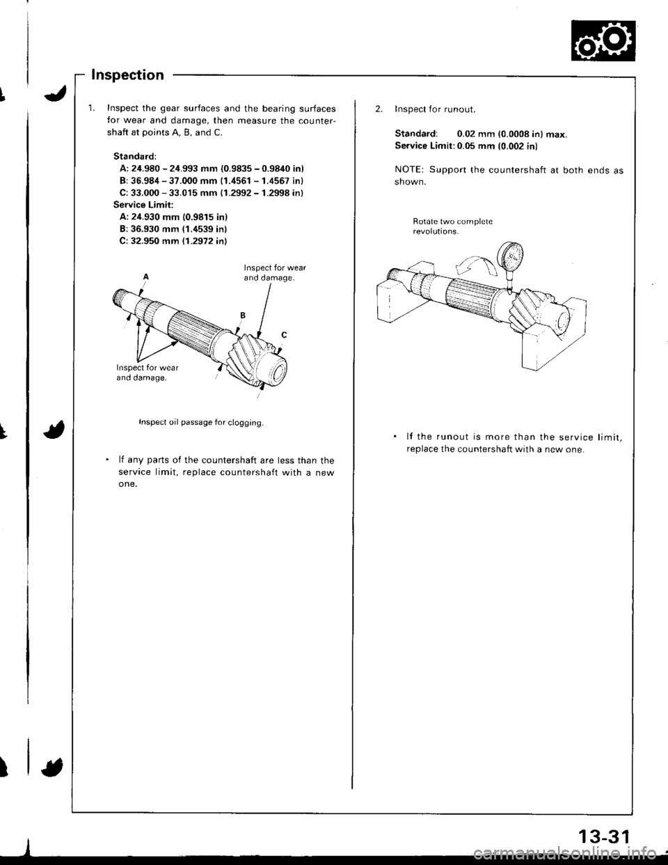
Inspect the gear surfaces and the bearing surfaces
for wear and damage, then measure the counter-
shaft at points A. B, and C.
Standard:
A: 24.980 - 24.993 mm {0.9835 - 0.9840 inl
B: 36.984 - 37.000 mm 11.4561 - 1.4557 inl
C: 33.000 - 33.015 mm (1.2992 - 1.2998 inl
Service Limit:
A: 24.930 mm {0.9815 inl
B:36.930 mm (1.4539 in)
C: 32.950 mm {.1.2972 inl
Inspect oil passage for clogg;ng.
lf any parts of the countershaft are less than the
service limit, replace countershaft with a new
one.
ano oamage,
I
2.Inspect for runout.
Standardr 0.02 mm (0.0008 in) max.
Service Limit:0.05 mm (0.002 in)
NOTE: Support the countershaft at both ends
shown.
Rotate two complete
lf the runout is more than the service limit,
replace the countershaft with a new one.
13-31
-,i
Page 398 of 1681
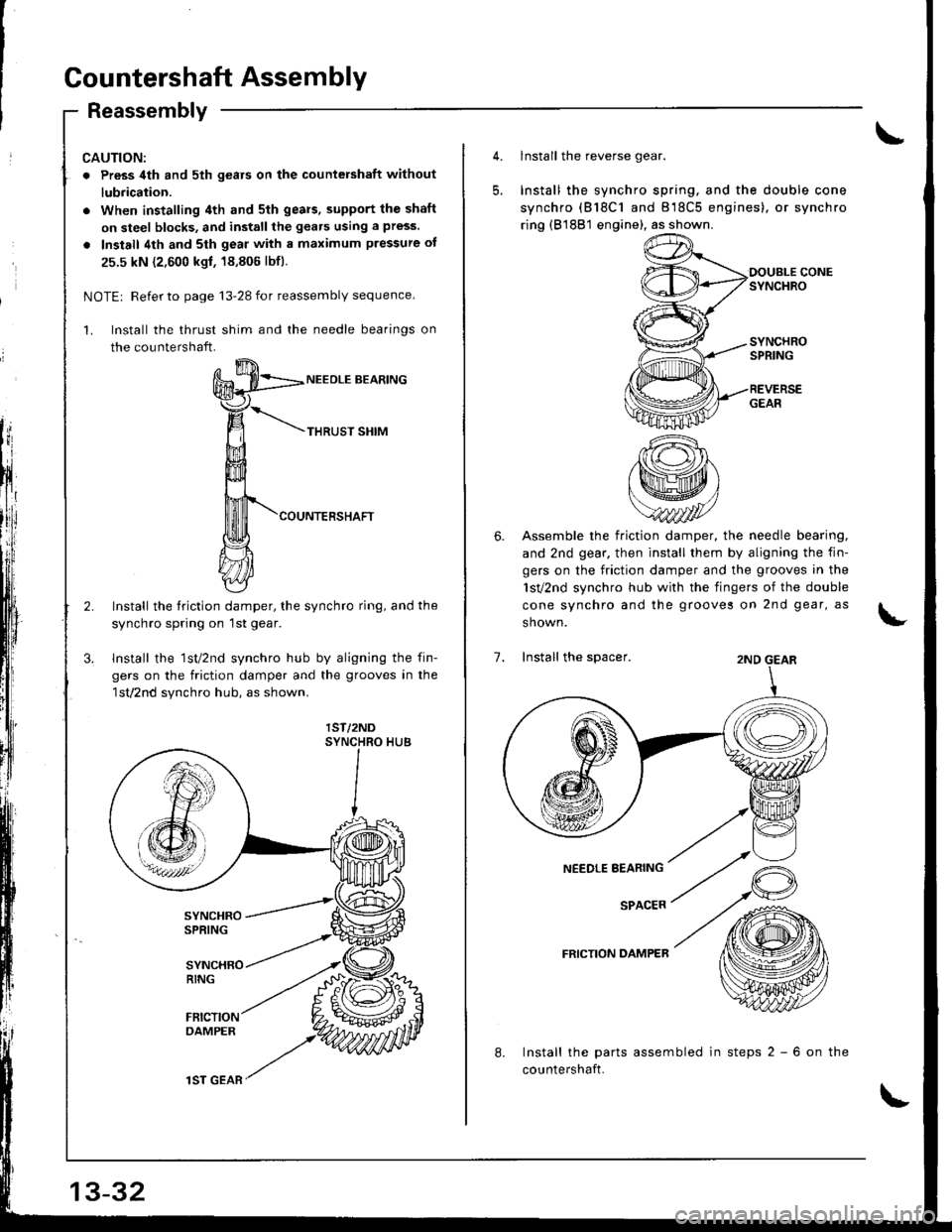
Gountershaft Assembly
Reassembly
CAUTION:
. Press 4th and sth gears on the countershaft without
lubrication.
. When installing 4th and 5th gears, supPort the shaft
on steel blocks, and install the gears using a press.
. Install 4th and sth geal with a maximum pressure of
25.5 kN {2,600 kgf, 18,806 lbfl.
NOTEr Refer to page '13-28 for reassembly sequence
Install the thrust shim and the needle bearings on
the countershaft.
NEEOLE BEARING
THRUST SHIM
COUNTERSHAFT
Install the friction damper, the synchro ring, and the
synchro spring on lst gear.
Install the lst/2nd synchro hub by aligning the fin-
gers on the friction damper and the grooves in the
lst/2nd synchro hub, as shown.
lST/2ND
13-32
1ST GEAR
5.
lnstall the reverse gear.
Install the synchro spring. and the double cone
synchro (818C1 and 818C5 engines). or synchro
ring (81881 engine), as shown.
OOUELE CONESYNCHRO
SYNCHROSPRING
REVERSEGEAR
6. Assemble the friction damper, the needle bearing.
and 2nd gear. then install them by aligning the fin-
gers on the friction damper and the grooves in the
1sv2nd synchro hub with the fingers of the double
cone synchro and the grooves on 2nd gear, as
shown.
7. Install the spacer.2ND GEAR
SPACER
FRICTION DAMPER
8.Install the parts assembled in steps 2 - 6 on the
countershaft.
Page 399 of 1681
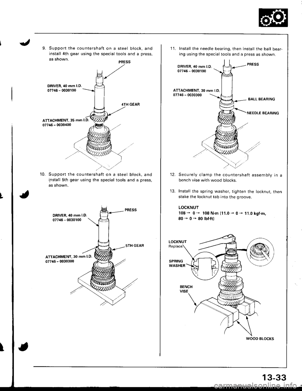
9. Support the countershaft on a steel block, and
install 4th gear using the special tools and a press,
as snown.
DRIVER, 40 mm l.O.07?46 - 0030100
4TH GEAR
ATTACHMENT, 35 mm I D.
07746 - 0030400
Support the countershaft on a steel block, and
install 5th gear using the special tools and a press,
as shown.
DRIVER,40 mm LD.
07746 - 0030100
ATTACHMENT, 30 mm I D.
077{6 - 0030300
10.
I
PRESS
11. Install the needle bearing, then install the balt bear-
ing using the specialtools and a press as shown.
DBIVER, 40 mm LD.07746 - 0030100
ATTACHMENT. 30 mm LD.07746 - 0030300
-..t
12.Securely clamp the countershaft assembly in abench vise with wood blocks.
Install the spring washer, tighten the locknut, then
stake the locknut tab into the groove.
LOCKNUT
108- 0" 108N.m (11.0- 0- 11.0kgf.m,
80'0+80rbr.ft)
WOOD BLOCKS
13-33
Page 400 of 1681
Synchro Sleeve, Synchro Hub
Inspection
1. lnspect gear teeth on all synchro hubs and synchro
sleeves for rounded off corners, which indicates
2. Install each synchro hub in its mating synchro
sleeve and check for freedom of movement.
NOTE: lf replacement is required, always replace
the synchro sleeve and synchro hub as a set.
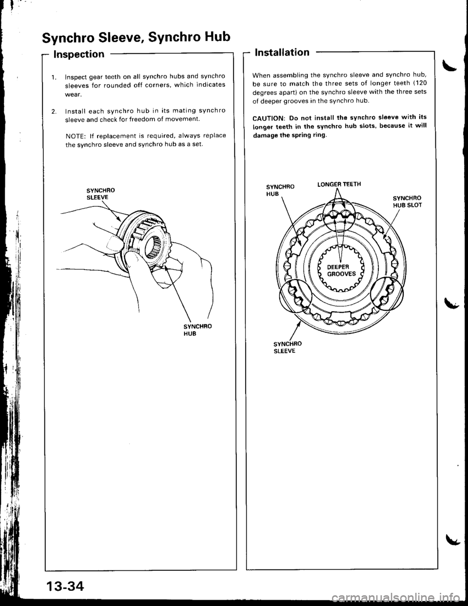
lnstallation
When assembling the synchro sleeve and synchro hub,
be sure to match the three sets of longer teeth (120
degrees apart) on the synchro sleeve with the three sets
of deeper grooves in the synchro hub.
CAUTION: Do not install the synchro sleeve with its
longer teeth in the synchro hub slots, because it will
damage the spring ring
SYNCHROHUB SLOT
fll!)
LONGER TEETH
SLEEVE
SYNCHROHUB
13-34