HONDA INTEGRA 1998 4.G Workshop Manual
Manufacturer: HONDA, Model Year: 1998, Model line: INTEGRA, Model: HONDA INTEGRA 1998 4.GPages: 1681, PDF Size: 54.22 MB
Page 431 of 1681

Description
Power Flow (cont'd)
lD+l or DglPosition, 2nd gear
1. Hydraulic pressure is applied to the 2nd clutch, which rotates together with the mainshaft, and the mainshaft 2nd
gear rolares.
2. Power is transmitted to the countershaft 2nd gear, which drives the countershaft
3. Power is transmitted to the final drive gear, which drives the final driven gear.
NOTE:
In @ or f_fl position. 2nd speed, hydraulic pressure is also applied to the 1st clutch, but since the rotation speed
ot 2nd gear exceeds that of 1st gear, power from lst gear is cut off at the one-way clutch
TOROUE CONVERTER
MAINSHAFT
COUNTERSHAFT
FINAL DRIVE GEAR
L
2ND CLUTCH
14-14
FINAL DRIVEN GEAR
Page 432 of 1681
I
I
I
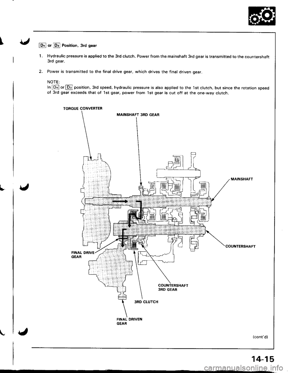
lDr or Drl Position, 3rd gear
1 . Hydraulic pressure is applied to the 3rd clutch. Power from the mainshaft 3rd gear is transmitted to the countershaft3rd gear.
2, Power is transmitted to the final drive gear, which d.ives the linal driven gear.
NOTE:
In @ or @] position, 3rd speed, hydraulic pressure is also applied 10 the 1st clutch, but since the rotarron speedof 3rd gear exceeds that ot 1st gear, power from lst gear is cut ott at the one-way clutch.
TOROUE CONVERTER
MAINSHAFT
COUNTERSHAFT
{cont'd}
14-15
MAINSHAFT 3RD GEAR
3RD CLUTCH
Page 433 of 1681
Description
Power Flow (cont'd)
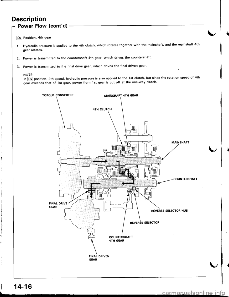
E Position, 4th goal
1. Hydraulic pressure is applied to the 4th clutch. which rotates together with the mainshaft. and the mainshaft 4th
gear rotales.
2. Power is transmitted to the countershaft 4th gear, which drives the countershaft'
3. Power is transmitted to the final drive gear, which drives the tinal dtiven gear'
NOTE:
ln @ position, 4th speed, hydraulic pressure is also applied to the lst clutch, but since the rotation speed of 4th
gear exceeds that of '1st gear, power from 1st gear is cut ofl at the one-way clutch
TOROUE CONVERTERMAINSHAFT 4TH GEAR
4TH CLUTCH
MAINSTIAFT
COUNTENSHAFT
{
14-16
L
Page 434 of 1681
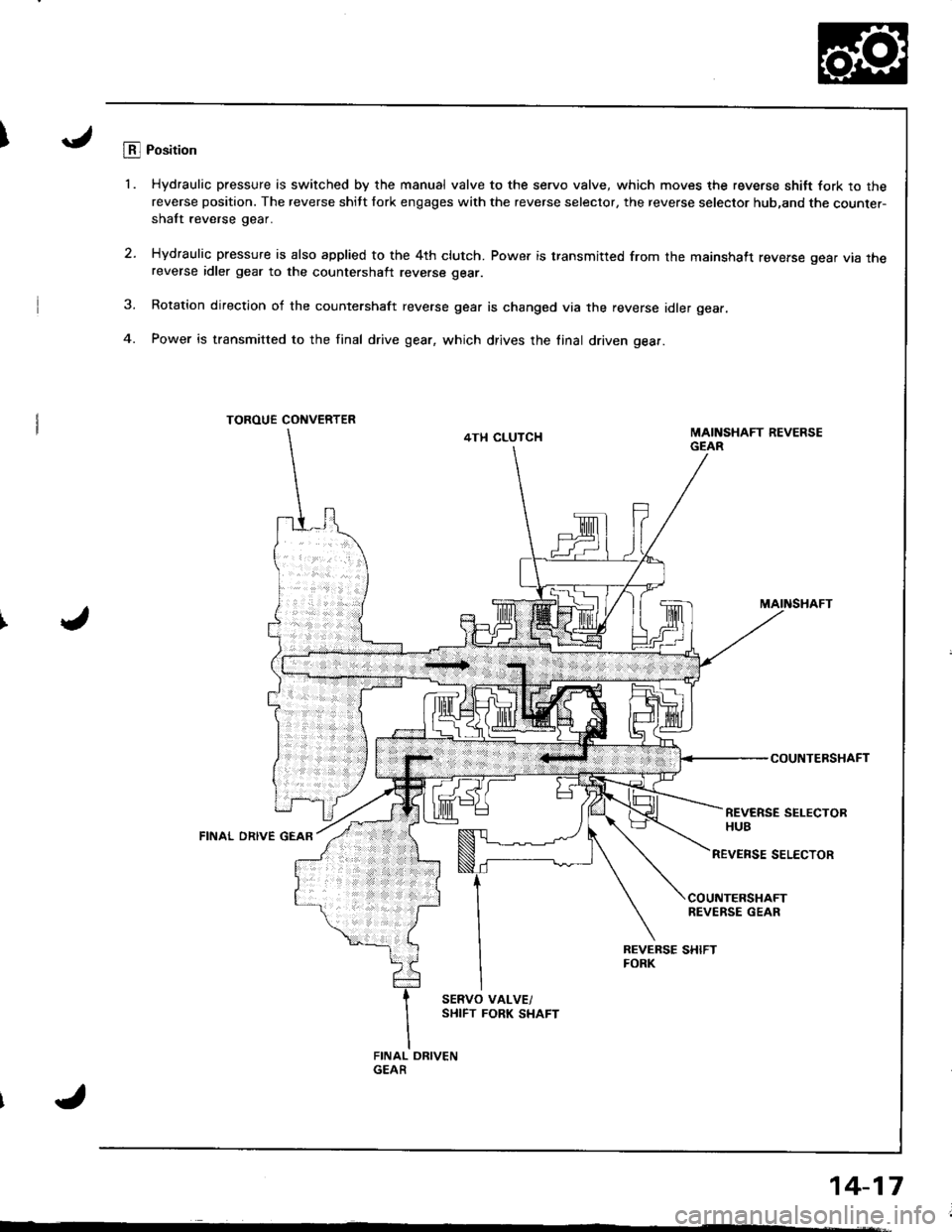
ILB.l Position
'1. Hydraulic pressure is switched by the manual valve to the servo valve, which moves the reverse shitt fork to thereverse position. The reverse shitt fork engages with the reverse selector, the reverse selector hub,and the counter-shaft reverse gear.
2. Hydraulic pressure is also applied to the 4th clutch. Power is transmitted from the mainshaft reverse gear vta rnereverse idler gear to the countershalt reverse gear.
3. Rotation direction of the countershaft reverse gear is changed via the reverse idler gear.
4. Power is transmitted to the final drive gear, which drives the linal driven gear.
TOROUE CONVERTER
4TH CLUTCH
MAINSHAFT
COUNTERSHAFT
REVERSE SELECTORHUBFINAL ORIVE GEAR
REVENSE SELECTOR
COUNTERSHAFTREVERSE GEAR
Page 435 of 1681
Description
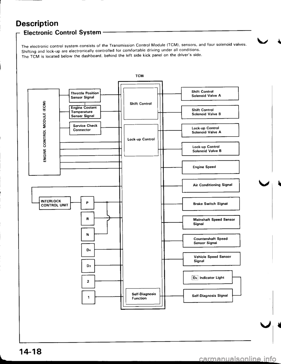
Electronic Control SYstem
14-18
{The electronic control system consists of the Transmission control Module {TcM), sensors, and four solenoid valves'
shifting and lock-up are electronically controlled tor comfortable driving under all conditions
The TCM is located below the dashboard, behind the left side kick panel on the driver's side.
Shilt Control
Lock-up ControlSolenoid Valve A
Lock up Control
Lock-up ControlSolenoid Valve I
I
Page 436 of 1681
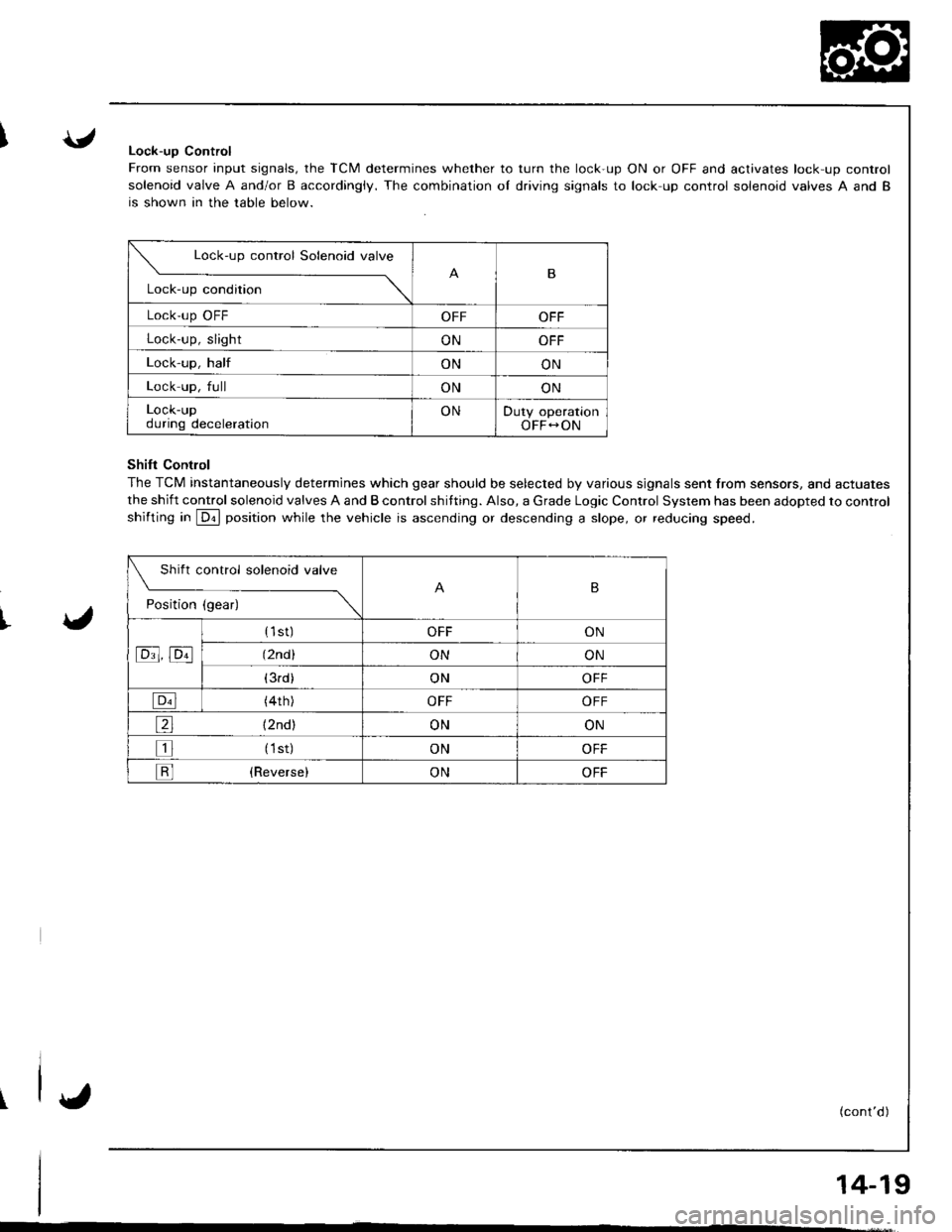
Lock-uD Control
From sensor input signals, the TCM determines whether to turn the lock-up ON or OFF and activates lock-up control
solenoid valve A and/or B accordingiy. The combination oI driving signals to lock up control solenoid valves A and B
is shown in the table below.
ShiIt Contlol
The TCM instantaneously determines which gear should be selected by various signals sent from sensors, and actuates
the shift control solenoid valves A and B control shifting. Also, a Grade Logic Control System has been adopted to control
shifting in @ position while the vehicle is ascending or descending a slope, or reducing speed.
w"'u"
Lock-up condition
-\B
Lock'up OFFOFFOFF
Lock-up, slightONOFF
Lock-up, halfONON
Lock up, fullONON
LOCK-Upduring decelerationONDuty operationOFF-ON
Shift control solenoid valve
t"dil"" d;------\
B
tc!t' tcll
{1st)OFFON
(2nd )ONON
(3rd)ONOFF
{4th)OFFOFF
e {2nd)ONON
tr (1st)ONOFF
tr (Reverse)ONOFF
I'
(cont'd)
14-19
Page 437 of 1681
Description
Elestronic Control System (cont'd)
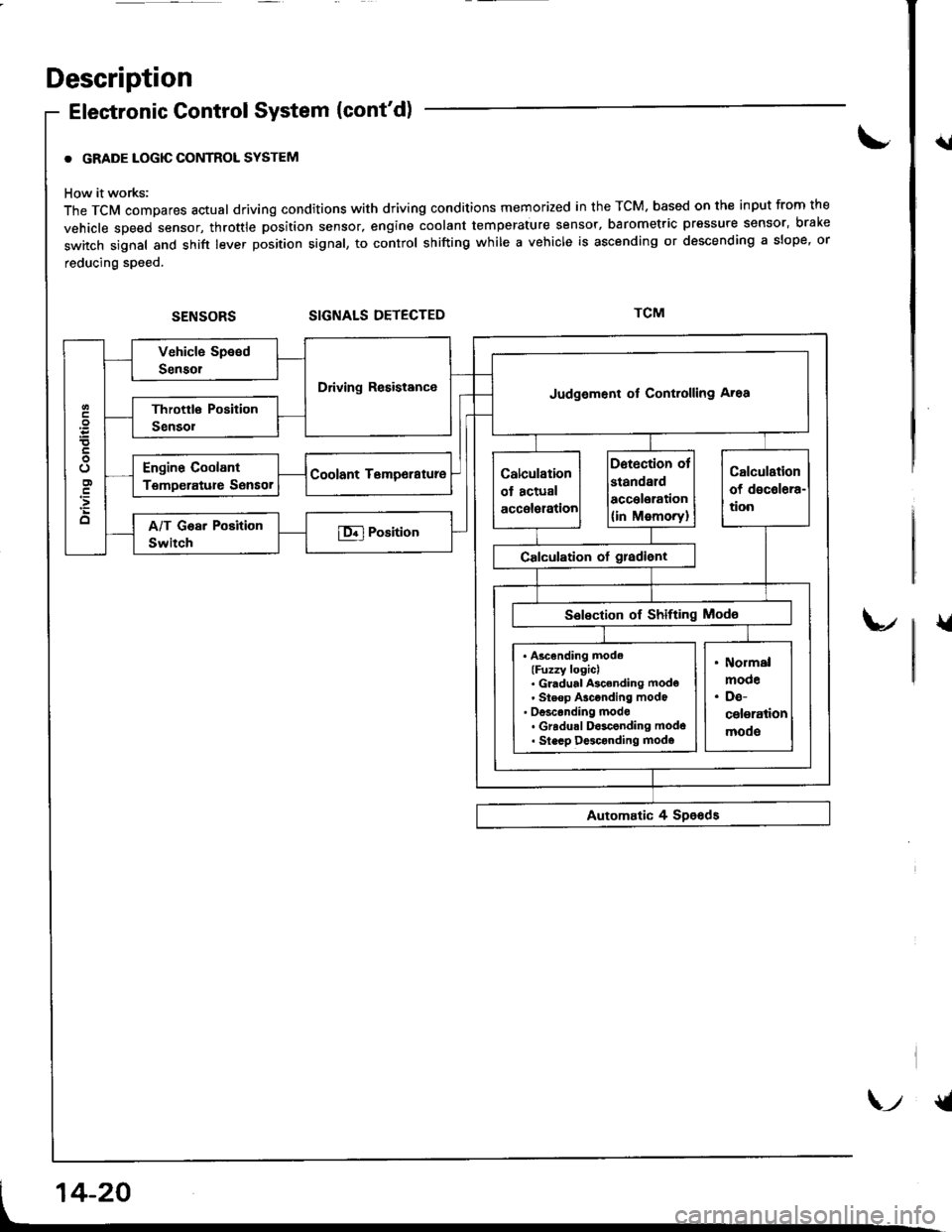
. GRADE LOGIC CONTROL SYSTEM
How it works:
The TCM compares actual driving conditions with driving conditions memorized in the TCM. based on th€ input from the
vehicle speed sensor, throttle position sensor, engine coolant temperature sensor, barometric pressure sensor, bral(e
switch signal and shift lever position signal, to control shifting while a vehicle is ascending or descending a slope, or
reducing speed.
SIGNALS DETECTED
{l
{
Driving ResistanceJudgement of Controlling Aroa
. Ascending mode(Fuzzy logicl. Gl.dual Ascending mode' Steop Asconding mode' oesconding mode. Gradu.l D$conding modo. Slecp D$conding modo
\-t {t
Page 438 of 1681
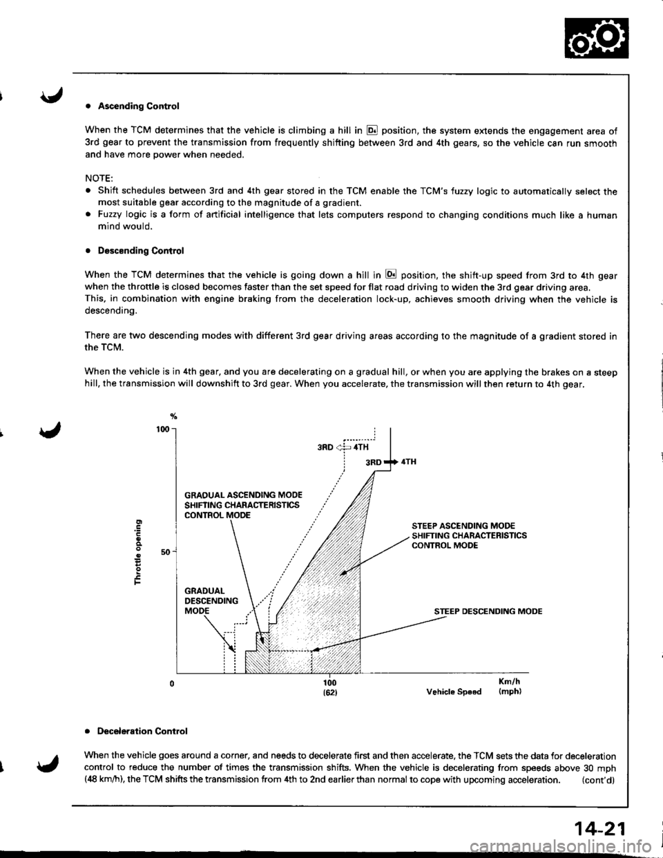
. Ascending Control
When the TCM determines that the vehicle is climbing a hill in E position, the system extends the engagement area of
3rd gear to prevent the transmission from frequently shifting between 3rd and 4th gears, so the vehicle can run smooth
and have more power when needed,
NOTE:
Shift schedules between 3rd and 4th gear stored in the TCM enable the TCM'S fuzzy logic to automatically select themost suitable gear according to the magnitude of a gradient.
Fuzzy logic is a form of artificial intelligence that lets computers respond to changing conditions much like a human
mind would,
. Descending Control
When the TCM determines that the vehicle is going down a hill in E position, the shift-up speed from 3rd to 4th gear
when the throttle is closed becomes faster than the set speed for flat road driving to widen the 3rd gear driving area.This. in combination with engine braking from the deceleration lock-up, achieves smooth driving when the vehicle is
descending,
There are two descending modes with different 3rd gear driving areas according to the magnitude of a gradient stored in
the TCM.
When the vehicle js in 4th gear, and you are decelerating on a gradual hill, or when you are applying the brakes on a steephill, the transmission will downshift to 3rd gear. When you accelerate, the transmission will then return to 4th gear,
GRAOUAL ASCENOING MOOESHIFTING CHARACTERISTICSCONTROL
STEEP DESCENDING MODE
Vehicle Speed
. Deceleraiion Control
When the vehicle goes around a corner, and needs to decelerate first and then accelerate. the TCM sets the data for deceleration
control to reduce the number of times the transmission shifts. When the vehicle is decelerating from speeds above 30 mph(,18 km/h), the TCM shifts the transmission from 4th to 2nd earlierthan normal to cope with upcoming acceleration. (cont'd)
E
F
Km/h(mph)
14-21
Page 439 of 1681
Description
Electronic Control System (cont'd)
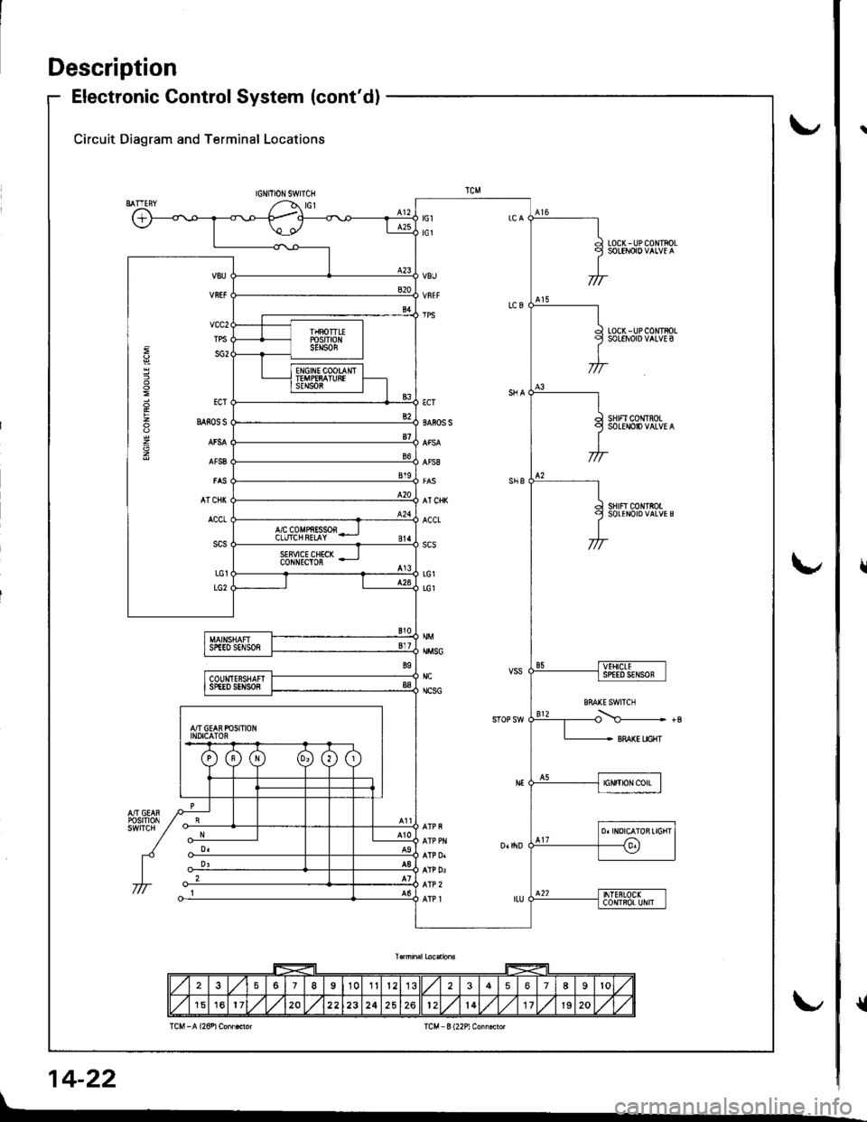
Circuit Diagram and Terminal Locations
IGNITIONSWITCH
LOC(-UPCONTFOL
LOCK - UP COIITBOLSOLENOIO VALVE B
SHIFI CONTROLSOLENOID VALVE A
sHrFtc0NtRotSOLENOIDVALVES
€cT
SAFOS S
AT CHK
ACCt
scs
LG1
LG1
NMSG
NC
NCSG
vcc2
TPS
sG2
ECT
BAios s
AT CNI(
ACCt
LG1
LG2
257I10112356789lo
151620222324252612l417lg20
14-22
r
{
Page 440 of 1681
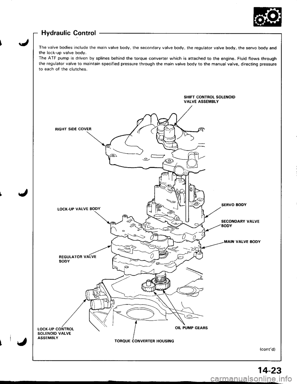
The valve bodies include the main valve body, the secondary valve body, the regulator valve body, the servo body andthe lock-up valve bodv.
The ATF pump is driven by splines behind the torque converter which is attached to the engine, Fluid {lows through
the regulator valve to maintain specified pressure through the main valve body to the manual valve, directing pressure
to each of the clutches.
SHIFT CONTROL SOLENOIDVALVE ASSEMBLY
RIGHT SIDE COVER
LOCK'UP VALVE BODYSERVO BODY
SECONDARY VALVEBODY
VALVE BODY
REGULATOR VBODY
LOCK-UPOIL PUMP GEARS
SOLENOID VALVEASSEMBLYTOROUEHOUSING
{cont'd)
%<->--::/ )C)
IrY,
14_23
'