HONDA INTEGRA 1998 4.G Workshop Manual
Manufacturer: HONDA, Model Year: 1998, Model line: INTEGRA, Model: HONDA INTEGRA 1998 4.GPages: 1681, PDF Size: 54.22 MB
Page 401 of 1681
Synchro Ring, Gear
Inspection
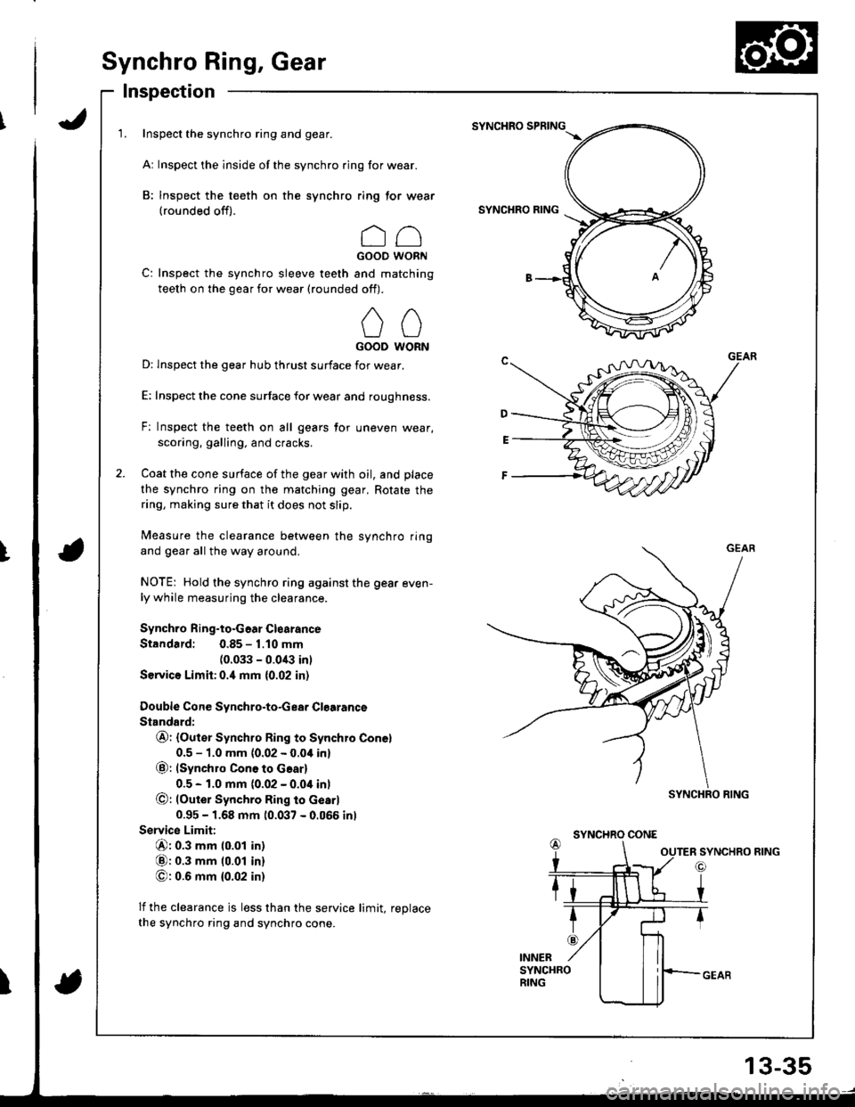
1. Inspect the synchro ring and gear.
Ar Inspect the inside of the synchro ring for wear.
B: Inspect the teeth on the synchro ring tor wear(rounded off).
ccGOOD WORN
C: Inspect the synchro sleeve teeth and matching
teeth on the gear for wear (rounded off).
00GOOD WORN
D: lnspect the gear hub thrust surface for wear.
E: Inspect the cone surtace for wear and roughness.
F: Inspect the teeth on all gears for uneven wear,
scoring, galling. and cracks.
Coat the cone surface of the gear with oil, and place
the synchro ring on the matching gear, Rotate the
ring, making sure that it does not slip.
Measure the clearance between the synchro ring
and gear all the way around.
NOTE: Hold the synchro ring against the gear even-ly while measuring the clearance.
Synchro Ring-to.Goar Clearance
Standard: 0.85 - 1.10 mm
(0.033 - 0.0/B inl
Service Limh:0.4 mm {0.02 in)
Double Cone Svnchro-to-Gea. Clgarance
Standard:
@r (Outer Synchro Ring to Synchro Conel
0.5 - 1.0 mm {0.02 - 0.04 in}
@: (synchro ConG to Gear)
0.5 - 1.0 mm (0.02 - 0.04 inl
@: lOute; Synchro Ring to Gearl
0.95 - 1.68 mm 10.037 - 0.066 inl
Servic€ Limit:
@: 0.3 mm (0.01 in)
@: 0.3 mm 10.01 in)
O: 0.6 mm {0.02 in}
lf the clearance js less than the service limit, reDlace
the synchro ring and synchro cone.
SYNCHRO SPRING
SYNCHRO RING
SYNCHRO CONE
I
SYNCHRO RING
13-35
Page 402 of 1681
Clutch Housing Bearing
Replacement
Mainshaft:
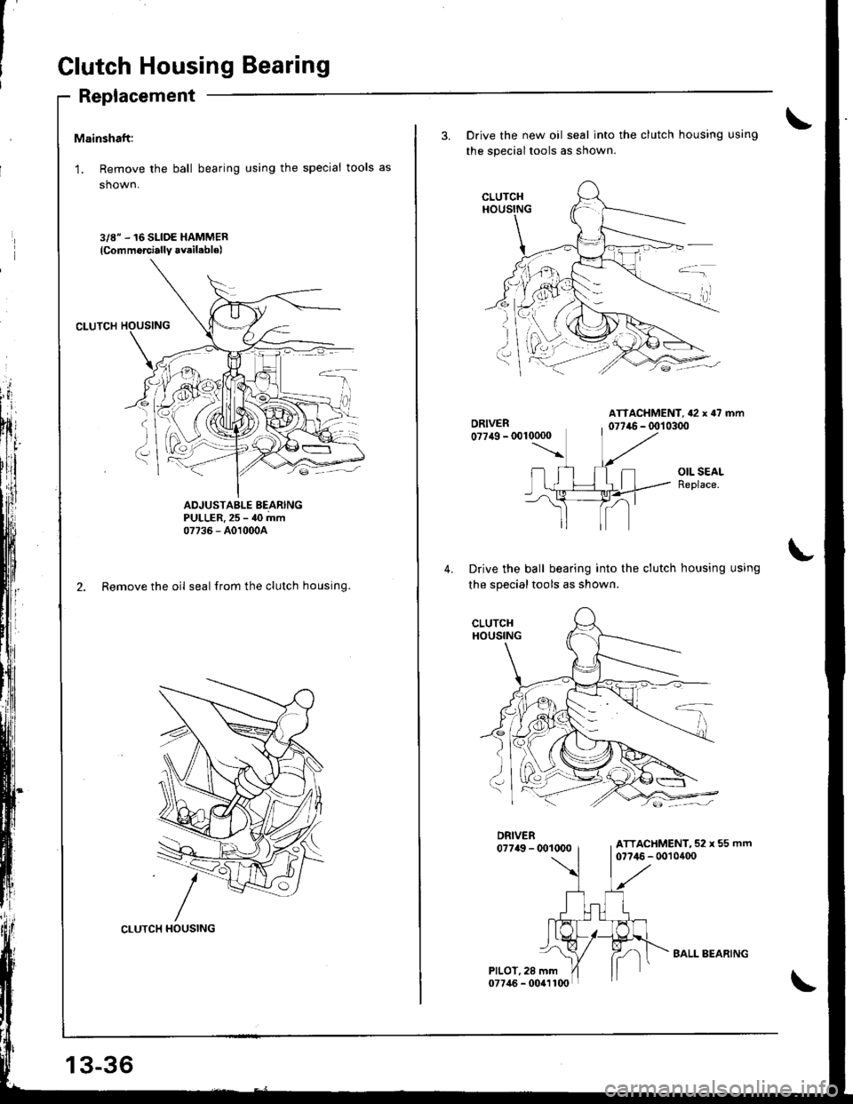
'L Remove the ball bearing using the special tools as
shown.
3/8" .16 SLIDE HAMMER
{Commorcially avsil.blo)
ADJUSTABLE BEARINGPULLER. 25 - 40 mm07736 - A010o0A
2. Remove the oil seal from the clutch housing.
CLUTCH HOUSING
13-36
BALL BEARING
3. Drive the new oil seal into the clutch housing using
the specialtools as shown.
ATTACHMENT, {2 x o7 mm077ir6 - (x)1 0300
OIL SEALReplace.
Drive the ball bearing into the clutch housing using
the specialtools as shown.
DRIVER07749 - @1U)0
PILOT, 28 mm07746 - 0041100
ATTACHMENT, 52 x 55 mm07?46 - 0010400
-: -,
Page 403 of 1681
Countershaft:
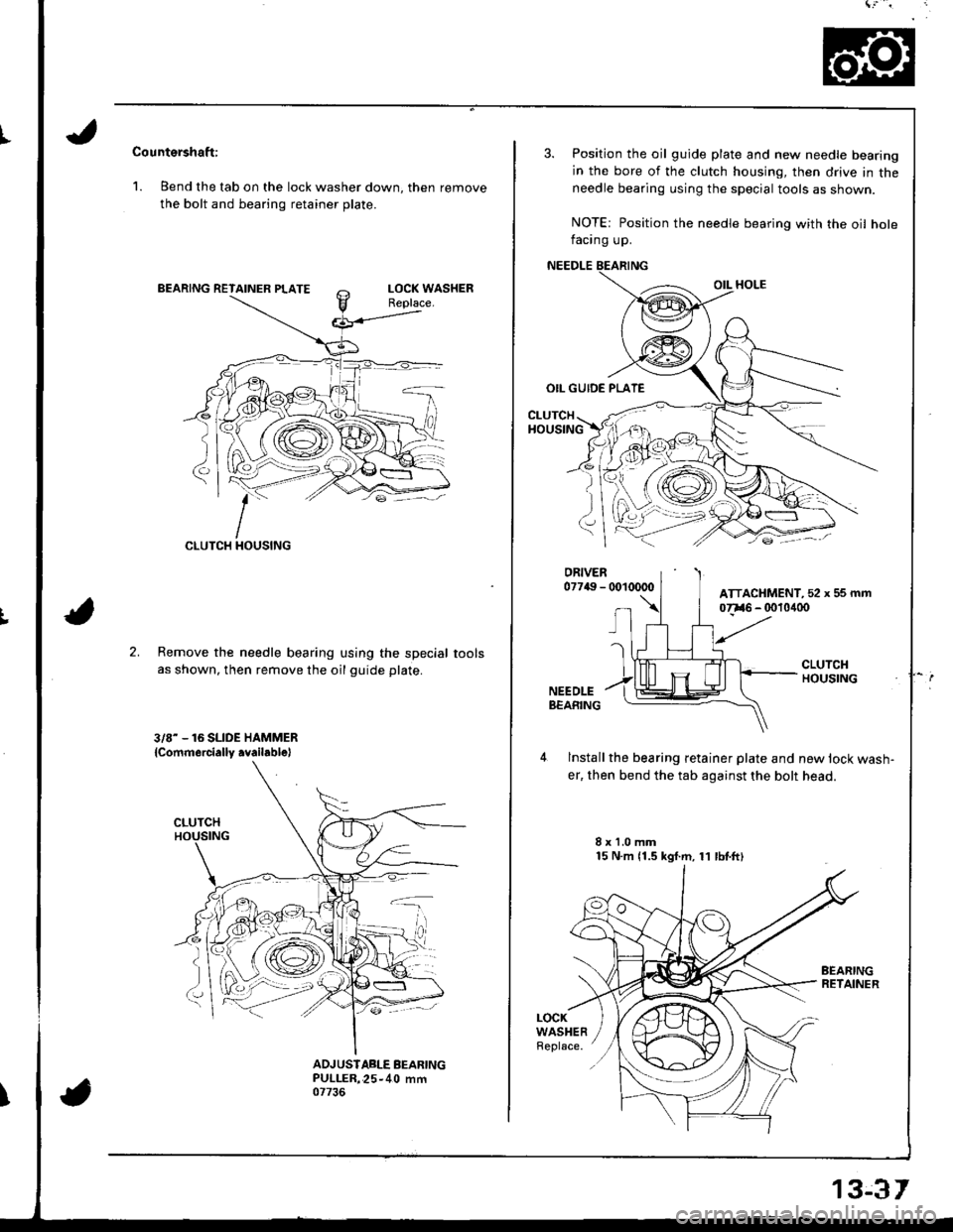
1. Bend the tab on the lock washer down, then remove
the bolt and bearing retainer plate.
CLUTCH
;:-
2.Remove the needle bearing using the special
as shown, then remove the oil guide plate.
3/8- - 16 SLIDE HAMMER
lcommercially .vailablel
tools
ADJUSIABLE BEARINGPULLER,25-40 mm07736
3. Position the oil guide plate and new needle bearing
in the bore of the clutch housing, then drive in theneedle bearing using the special tools as shown.
NOTE: Position the needle bearing with the oil holefacing up.
NEEDLE
OIL HOLE
OIL GUIDE PLATE
CLUTCHHOUSING
lnstall the bearing retainer plate and new lock wash-
er, then bend the tab against the bolt head.
8x1.0mm15 N.m 11.5 kgf.m, 11 lbtftl
LOCKWASHERReplace.
ATTACHMENT, 52 x 5s mm
13€r
Page 404 of 1681
Mainshaft Thrust Glearance
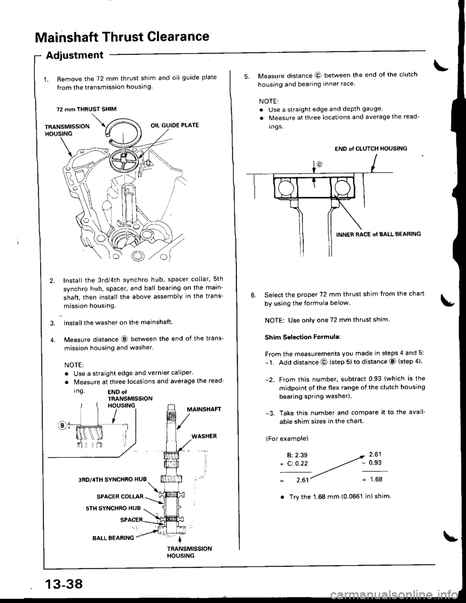
1. Remove the 72 mm thrust shim and oil guide plate
from the transmission housing
72 mm THRUST SHIM
Adiustment
TRANSMISSIONHOUSING
\,
Bo
OIL GUIDE PLATE
Install the 3rd/4th synchro hub, spacer collar,5th
synchro hub, spacer, and ball bearing on the maln-
shaft, then install the above assembly in the trans-
mission housing.
lnstallthe washer on the mainshaft.
Measure distance @ between the end of the trans-
mission housing and washer'
NOTE:
. Use a straight edge and vernier caliper'
a N4easure at three locations and average the read
Ing.END ofTRANSMISSIONHOUSING
3RD,/4TH SYNCHRO HUB
SPACER COLLAR
sTH SYNCHRO HUB
MAINSHAFT
WASHER
BALL BEARING
. Try the 1.68 mm (0.0661 inI shim.
5. Measure distance @ between the end of the clutch
housing and bearing inner race
NOTE:
. Use a straight edge and depth gauge
a Measure at three locations and average the read-
ings.
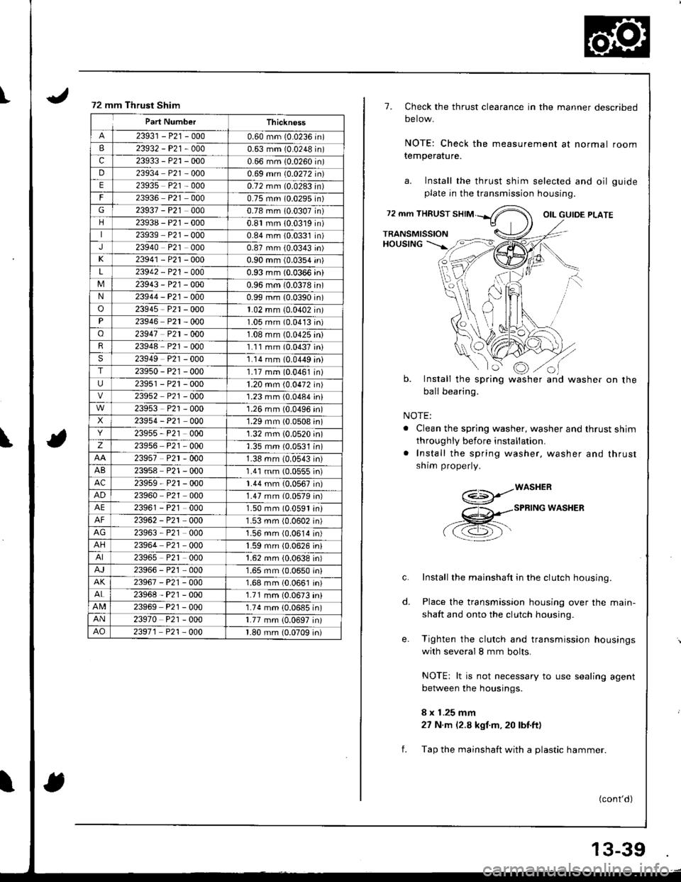
Select the prcpe( 72 mm thrust shim from the chart
by using the formula below.
NOTE: Use only one 72 mm thrust shim
Shim Selection Formula:
From the measurements you made in steps 4 and 5:
- 1. Add distance @ (step 5) to distance @ (step 4).
-2. Frcm this number. subtract 0.93 (which is the
midpoint ot the flex range of the clutch housing
bearing spring washer).
-3. Take this number and compare it to the avail-
able shim sizes in the chart.
(For examplel
6.
B:2.39
+ C: 0.22- 0.93
1.68
END of CLUTCH HOUSING
INNER RACE o{ BALL BEARING
Page 405 of 1681
I
\
72 mm Thrust Shim
Part NumberThickness
23931 - P21 -0000.60 mm (0.0236 in)
B23932-P21-0000.63 mm (0.0248 in)
c23933 - P21 -0000.66 mm (0.0260 in)
D23934 P21 0000.69 mm (0.0272 in)
E23935 P21 - 0000.72 mm (0.0283In)
23936 P21 0000.75 mm (0.0295n)
G23937 - P21 0000.78 mm 10.0307n)
23938 - P21 -0000.81 mm 10.0319n)
23939 P21 - 0000.84 mm {0.0331n)
J23940 P21 0000.87 mm (0.0343 in)
K23941 - P21 -0000.90 mm (0.0354 in)
L23942 - P21 - 0000.93 mm (0.0366 in)
M23943 - P21 -0000.96 mm (0.0378 in)N23944-P21 -0000.99 mm {0.0390 in)
o23945 - P21 -0001.02 mm (0.0402 in)
23946 P2r - 0001.05 mm (0.0413 in)
o23947 P2r - 0001.08 mm (0.0425 in)
23948 P21 - 0001.11 mm (0.0437;ni
23949 P21 - 0001.14 mm (0.0449 ini
T23950-P21 -0001.17 mm (0.0461 in)
23951 - P21 -0001.20 mm (0.0472 in)
23952 P21 - O001.23 mm (0.0484 in)
23953 P21 - 0001.26 mm (0.0496 'n)
23954 - P21 000'1.29 mm (0.0508 in)
23955, P21 0001.32 mm (0.0520 in)
z23956 P21 - 0001.35 mm (0.0531 in)
23957 P2r - 0001.38 mm (0.0543 in)
AB23958 P21 - 0001.41 mm (0.0555 in)
AC23959-P21 -0001.44 mm (0.0567 in)
AD23960 P2r 0001.47 mm (0.0579 in)
AE23961 - P21 000L50 mm 10.0591 rn,
23962 - P21 0001.53 mm {0.0602 in)
AG23963, P21 0001.56 mm (0.0614 in)
AH23964 P21 0001.59 mm (0.0626 jn)
23965 P21 0001.62 mm (0.0638 in)
23966 - P21 0001.65 mm (0.0650 in)
AK23967-P2t-0001.68 mm (0.0661 In)
23968-P21 -0001.71 mm (0.0673 in)
23969 P21 - 0001.74 mm (0.0685 in)
AN23970 P21 - 0001.77 mm {0.0697 in)
AO23971 P21 - 000'l -80 mm {0.0709 in)
1.
72 mm THRUST
TRANSMISSIONHoustNG --'-.rft=>t
o
Check the thrust clearance in the manner described
oerow.
NOTE: Check the measurement at normal room
temperature.
a. Install the thrust shim selected and oil guide
plate in the transmission housing.
OIL GUIOE PLATE
b.
f.
NOTE:
. Clean the spring washer, washer and thrust shim
throughly before installation,
. Install the spring washer, washer and thrust
shim properly.
- -- /wAsHER(€>P-
X -spnrruc wlssen
a a.7l=\-\-
Install the mainshaft in the clutch housing.
Place the transmission housing over the main-
shaft and onto the clutch housing.
Tighten the clutch and transmission housings
with several I mm bolts.
NOTE: lt is not necessary to use sealing agent
between the housings.
8 x 1.25 mm
27 N.m (2.8 kgf.m, 20 lbt.ft)
Tap the mainshaft with a plastic hammer.
c.
o.
t:oInstall the spring
ball bearing.
wash erand washer on the
(cont'd)
il
13-39
Page 406 of 1681
Mainshaft Thrust Clearance
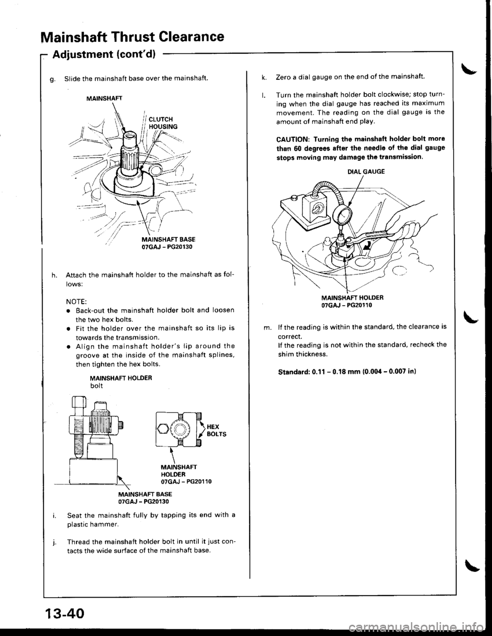
g. Slide the mainshaft base over the mainshaft.
Adjustment (cont'dl
/\
/-
MAINSHAFT BASE07GAJ - PG20130
Aftach the mainshaft holder to the mainshaft as fol-
lows:
NOTE:
o Eack-out the mainshaft holder bolt and loosen
the two hex bolts.
. Fit the holder over the mainshaft so its lip is
towards the transmission.
. Align the mainshaft holder's lip around the
groove at the inside of the mainshaft splines,
then tighten the hex bolts.
MAINSHAFT HOLDERbolt
MAINSHAFT BASE07GAJ - PG20130
Seat the mainshaft fully by tapping its end with a
plastic hammer.
Thread the mainshaft holder bolt in until it just con-
tacts the wide surface of the mainshaft base.
MAINSHAFT
f----M---E
|".ffi f\.xex
I \J \--l./ l/ Borrs
L- LE
\
MAINSHAfiHOLDER07GAJ - PG20110
13-40
Zerc a dial gauge on the end of the mainshaft.
Turn the mainshaft holder bolt clockwise; stop turn-
ing when the dial gauge has reached its maximum
movement. The reading on the dial gauge is the
amount of mainshaft end plav.
CAUTION: Turning the mainshaft holder bolt more
than 60 degrees after the needle of the dial gauge
stops moving may damage the transmission.
MAINSHAFT HOLDER07GAJ - PG20110
lf the reading is within the standard, the clearance is
correct.
It the reading is not within the standard, recheck the
shim thickness.
Standard: 0.11 - 0.18 mm (0.004 - 0.007 in)
DIAL GAUGE
Page 407 of 1681
I
t
\
Transmission
Reassembly
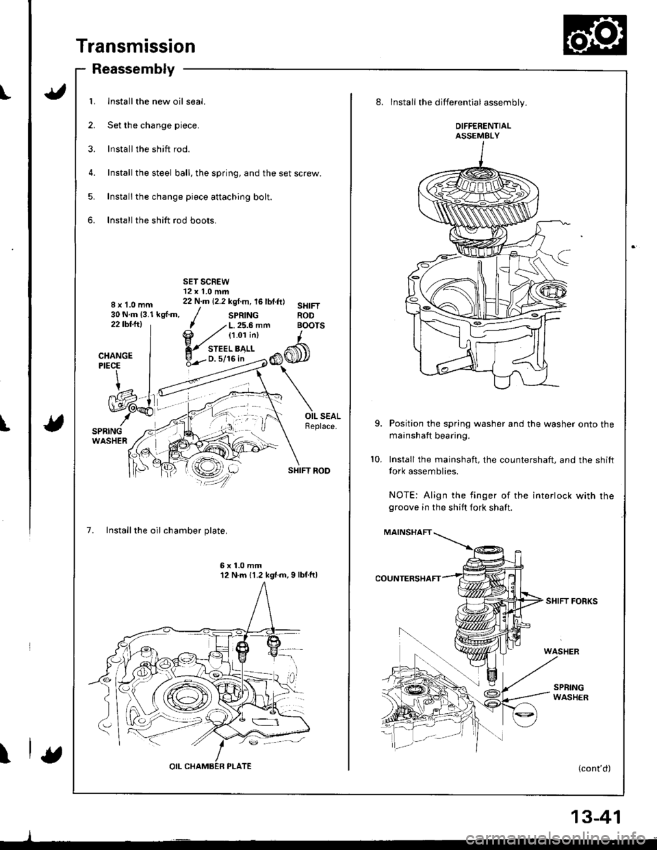
1. Install the new oil seal.
2. Set the change piece.
3. lnstall the shift rod.
4. Install the steel ball, the spring, and the set screw.
5. Install the change piece attaching bolt.
6. Install the shift rod boots.
8x1.0mm30 N.m (3.1 kgf.m,22tbfitl
SHIFT ROD
7. Installthe oil chamber plate.
7 .' L. 25.6 mfi BOI
@ ,zt tt.o'ti"t I
Y-",:'b>,",CI
6x1.0mm12 N.m {1.2 kgl.m,9 lbf.ft)
8. Install the differential assembly.
DIFFERENTIALASSEMBLY
Position the spring washer and the washer onto the
mainshaft bearing.
Install the mainshaft, the countershaft. and the shift
fork assemblies.
NOTE: Align the finger of the interlock with rhegroove in the shift fork shaft.
MAINSHAFT
SHIFT FORKS
(cont'd)
10.
13-41
Page 408 of 1681
Transmission
Reassembly (cont'dl
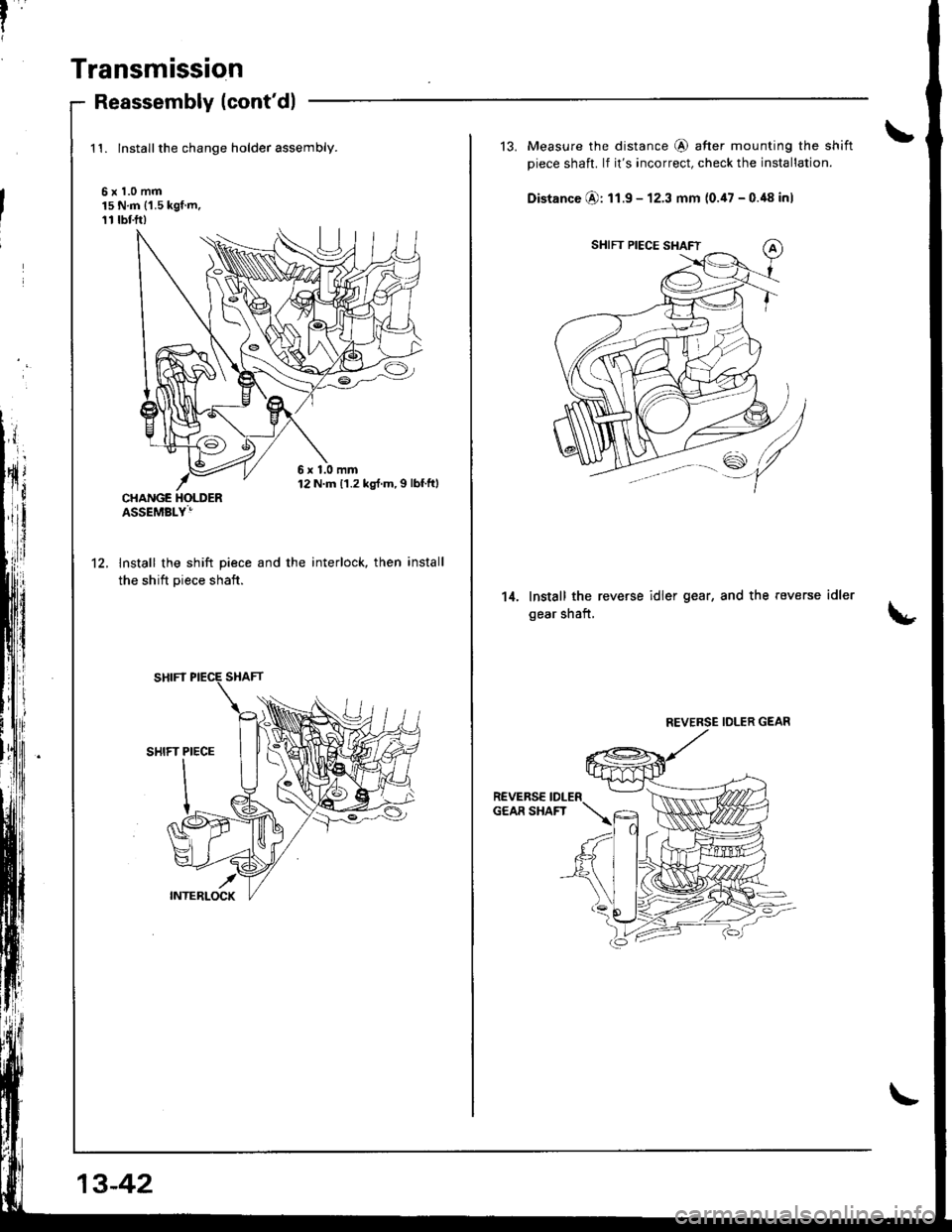
1't. lnstallthe change holder assembly.
6x1.0mm15 N.m ('1.5 kgf.m,11 rbf.ft)
lnstall the shift piece and the
the shift piece shaft.
interlock, then install't2.
6x1.0mm12 N.m 11.2 kg{.m,I lbf.ftl
13-42
13. Measure the distance @ after mounting the shift
piece shaft. lf it's incorrect, check the installation.
Distance @: 11.9 - 12.3 mm (0.47 - 0.48 inl
Install the reverse idler gear, and the reverse
gear shaft,
idler14.
REVERSE IDLER GEAR
Page 409 of 1681
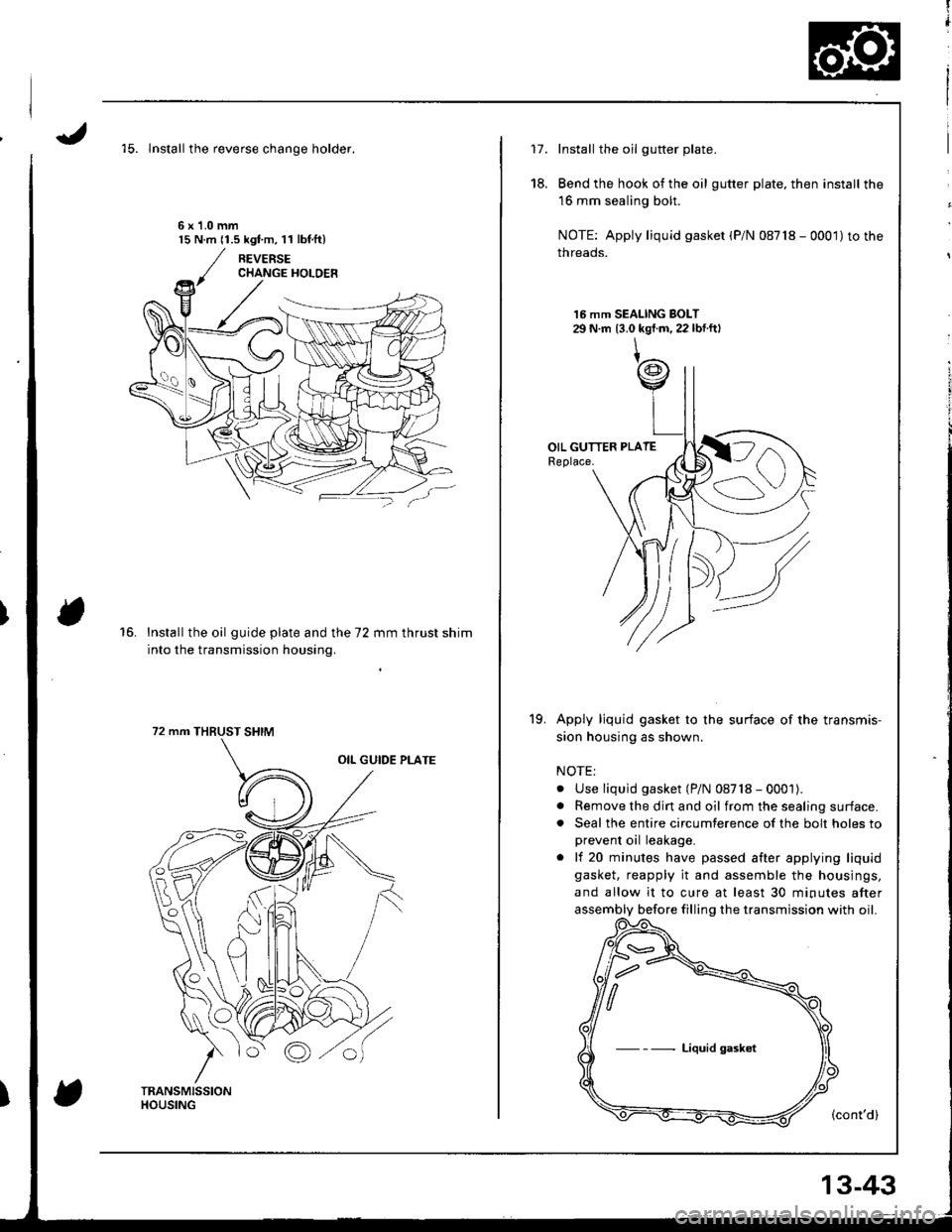
'15. lnstall the reverse chanqe holder.
6x1.0mm15 N.m 11.5 kgt m, l l lbf.ft)
16.Install the oil guide plate and the 72 mm thrust shim
into the transmission housing.
72 mm THBUST SHIM
fl
t
i
17.Install the oil gutter plate.
Bend the hook of the oil gutter plate, then install the
16 mm sealing bolt.
NOTE: Apply liquid gasket (P/N 08718 - 0001)to the
threads.
16 mm SEALING BOLT29 N.m 13.0 kgt.m, 22 lbf.ftl
Apply ljquid gasket to the surface of the transmis-
sion housing as shown.
NOTE:
. Use liquid gasket (P/N 08718 - 0001).. Remove the dirt and oil from the sealing surface.. Seal the entire circumterence of the bolt holes to
prevent oil leakage.
. lf 20 minutes have passed after applying liquid
gasket, reapply it and assemble the housings,
and allow it to cure at least 30 minutes after
assembly before filling the transmission with oil.
(cont'd)
18.
19.
Liquid gaskot
13-43
Page 410 of 1681
Transmission
20.
21.
Reassembly (cont'dl
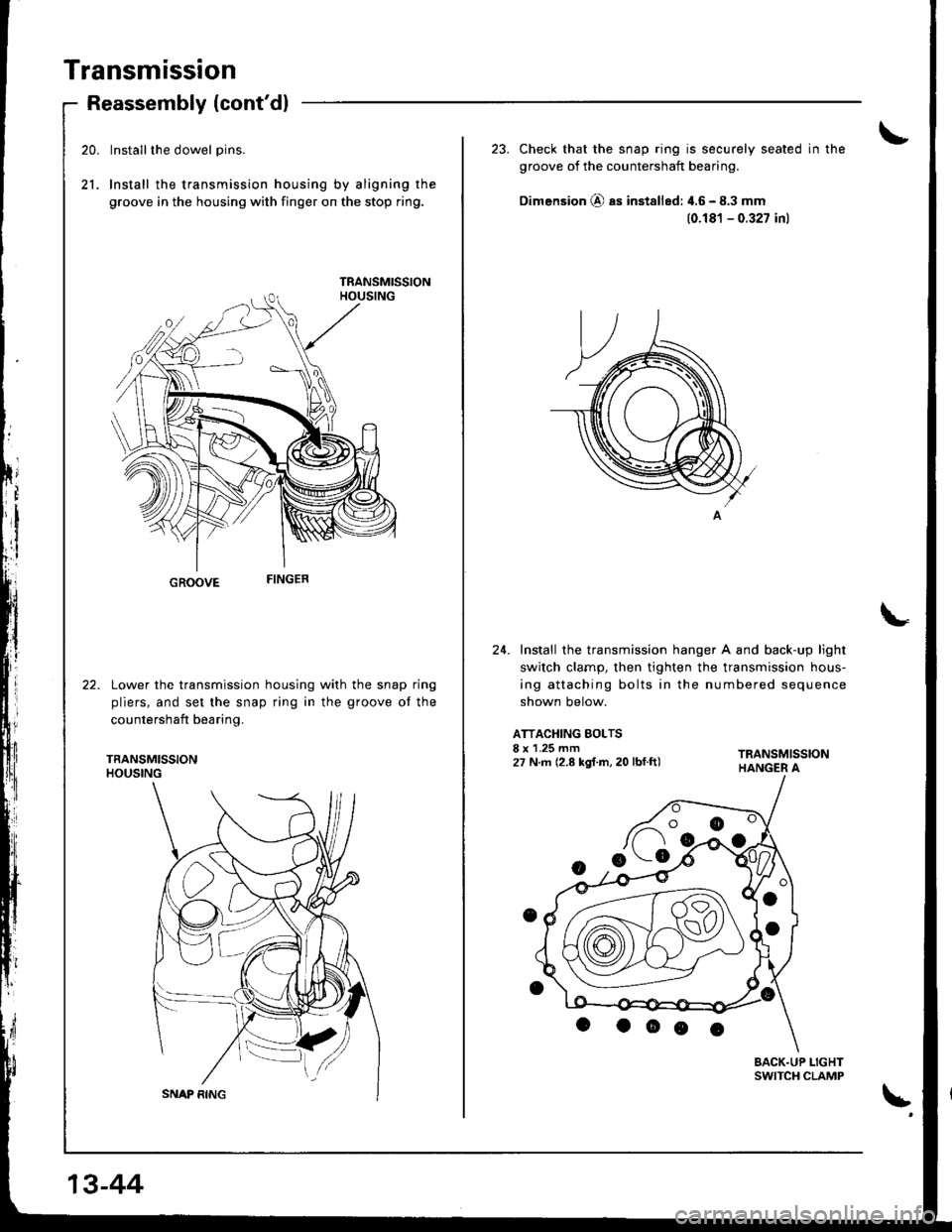
Installthe dowel pins.
Install the transmission housing by aligning the
groove in the housing with finger on the stop ring.
GROOVE
Lower the transmission housing with the snap ring
pliers, and set the snap ring in the groove of the
countershaft bearing.
TRANSMISSIONHOUSING
13-44
23. Check that the snap ring is securely seated in the
groove of the countershaft bearing.
Dimension @ as installed: 4.6 - 8.3 mm
(0.181 - 0.327 inl
24. Install the transmission hanger A and back-up light
switch clarnp, then tighten the transmission hous-
ing attaching bolts in the numbered sequence
shown below.
ATTACHING BOLTSI x 1.25 mm27 N.m (2.8 kgf.m, 20 lbf.ft)
BACK.UP LIGHTSWITCH CLAMP
\'