HONDA INTEGRA 1998 4.G Workshop Manual
INTEGRA 1998 4.G
HONDA
HONDA
https://www.carmanualsonline.info/img/13/6069/w960_6069-0.png
HONDA INTEGRA 1998 4.G Workshop Manual
Trending: compression ratio, Door lock repair, height, Cylinder, fuse box diagram, radiator cap, OBD port
Page 381 of 1681
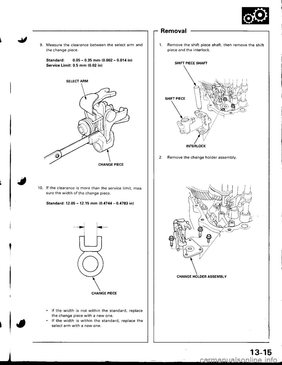
9.Measure the clearance between the select arm
the change piece.
Standard: 0.05 - 0.35 mm {0.002 - 0.014 in)
Service Limit: 0.5 mm {0.02 inl
Removal
Remove the shift piece shaft, then remove the shiftpiece and the interlock.
2. Remove the change holder assembly.
and
10.lf the clearance is more than the service limit, mea
sure the width of the change piece-
Standard: 12.05 - 12.15 mm {0.4744 - 0.4783 inl
CHANGE PIECE
lf the width is not within the standard, replace
the change piece with a new one.
lf the width is within the standard, replace the
select arm with a new one.
SELECT ARM
SHIFT PIECE SHAFT
INTERLOCK
Page 382 of 1681
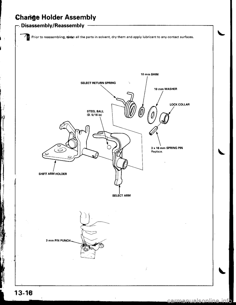
Ghattle Holder Assembly
Disassembly/Reassembly-:. Lrrl'al':'Err|rrry, nscs':'srrrrrry -
.---..rt/ El Prior to reassembling, qean all the parts in solvent, dry them and apply lubricant to any contact surfaces.f-
SELECT RETUBN SPRING
13-16
Page 383 of 1681
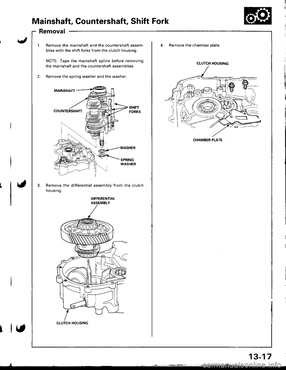
Mainshaft, Countershaft, Shift Fork
Removal
mainshaft and the countershaft assem-
? shift forks from the clutch housing.
the mainshaft spline before removing
ft and the countershaft assemblies.
spring washer and the washer.
differential assembly from the clutch
OIFFERENTIALASSEMBLY
4. Remove the chamber plate.
SPRINGWASHER
1.Remove the m€
biies with the sl
NOTE: Tape th
the mainshaft a
Remove the spr
MAINSHAFT
COUNTERSHAFT
Remove the
housr ng.
CLUTCH HOUSING
CLUTCH HOUSING
CHAMBER PLATE
etsY')
2r}5
(\cyl,//_\::iv/.
13-17
Page 384 of 1681
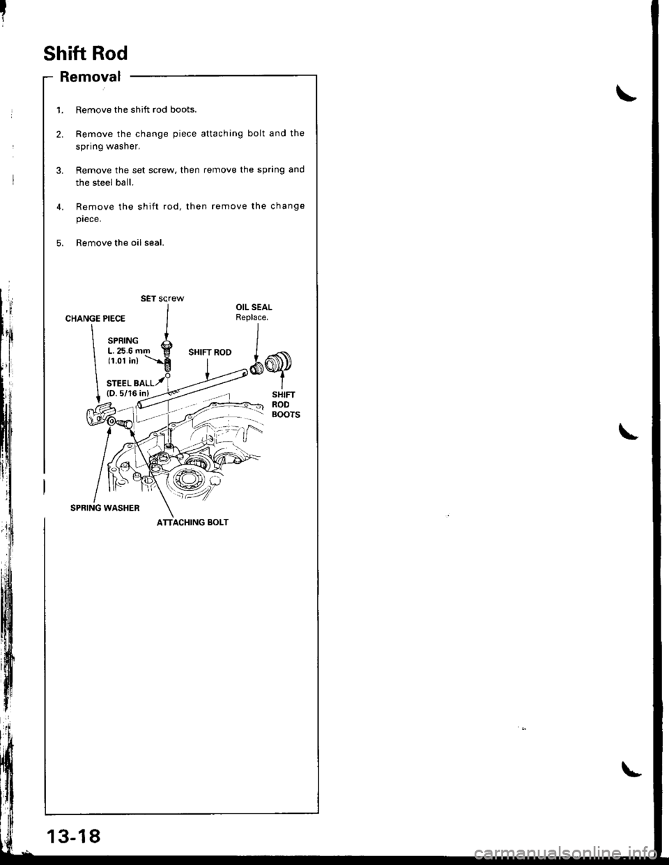
Shift Rod
- Removal
13-18
1. Remove the shift rod boots.
2. Remove the change piece attaching bolt and the
spring washer,
3. Remove the set screw. then remove the spring and
the steel ball.
4,
5.
Remove the shift rod, then remove the change
prece.
Remove the oil seal.
CHANGE
\
\
I
PIECE
SPRINGL.25.6 r(1.01 in)
STEEL B(D.5/16
OIL SEALReplace.
*q
SHIFTRODBOOTS
SPRING WASHER
SET screw
ATTACHING BOLT
Page 385 of 1681
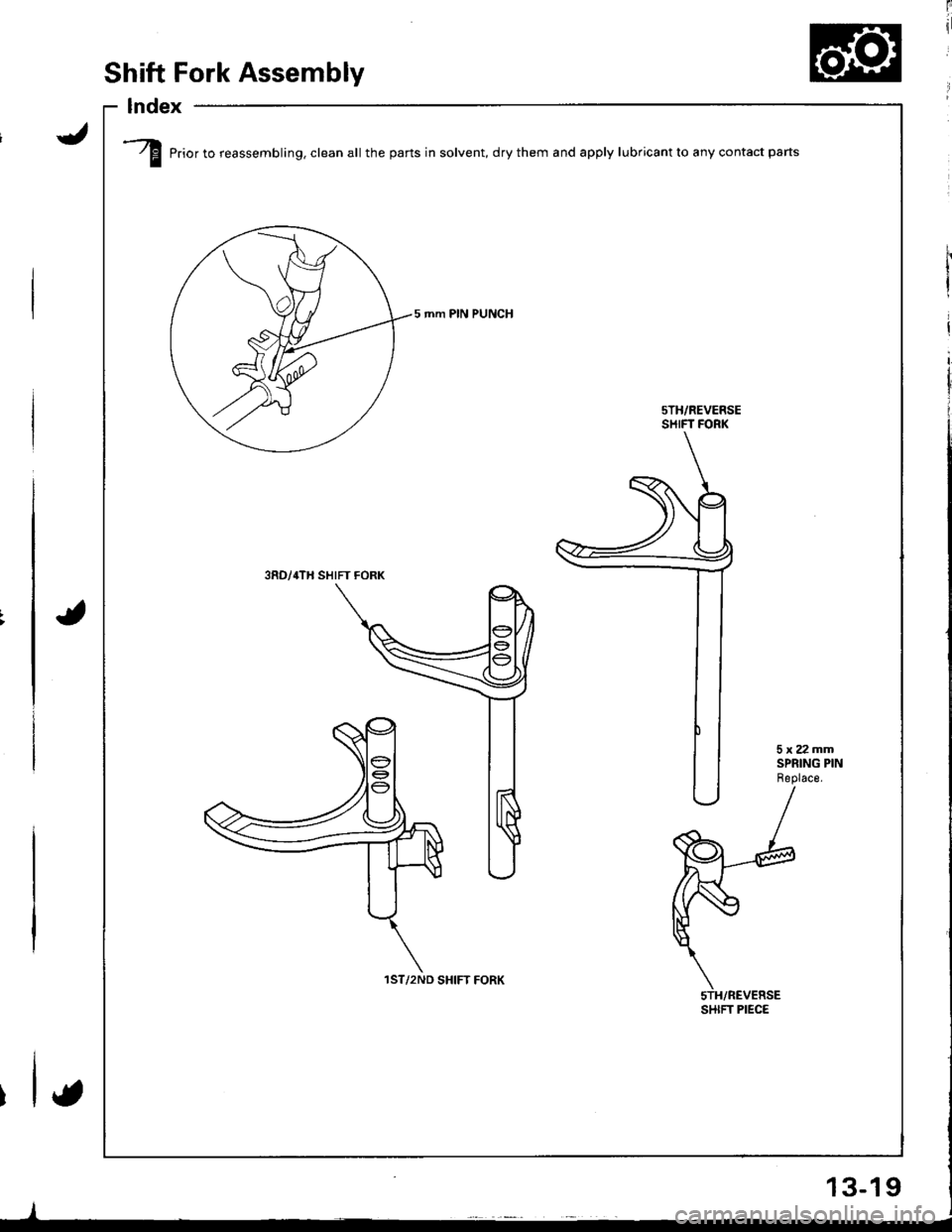
/f Prior to reassembling. clean all the parts in solvent, drythem and apply lubricantto any contact parts
5 mm PIN PUNCH
sTH/REVERSESHIFT FORK
3RD/,rTH SHIFT FORK
1ST/2ND SHIFT FORK
SHIFT PIEC€
Shift Fork Assembly
lndex
-/
lI
t
{
13-19
Page 386 of 1681
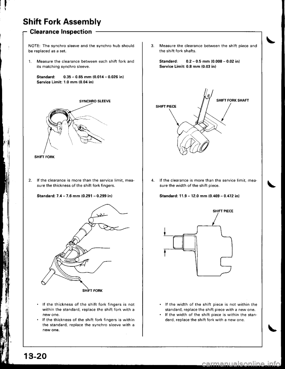
Shift Fork Assembly
Clearance Inspection
NOTE: The synchro sleeve and the synchro hub shouldh6 ronlr.o.l ,.. car
Measure the clearance between each shift fork and
its matching synchro sleeve.
Standard: 0.35 - 0.65 mm {0.014 - 0.026 inl
Service Limit: 1-0 mm 10.04 inl
SHIFT FORK
lf the clearance is more than the service limit, mea-
sure the thickness of the sh ift fork finoers.
Standard: 7.il - 7.6 mm (0.291 - 0.299 in)
lf the thickness of the shift fork fingers is not
within the standard, replace the shift fork with a
lf the thickness of the shift fork fingers is within
the standard, replace the synchro sleeve with a
new one.
3. Measure the clearance between the shift piece and
the shift fork shafts.
Standard: 0.2 - 0.5 mm (0.008 - 0.02 inl
Service Limit: 0.8 mm (0.03 inl
SHIFT PIECE
It the clearance is more than the service limit,
sure the width of the shift piece.
Standard: 11.9 - 12.0 mm (0.a69 - 0.a72 inl
lf the width of the shift piece is not within the
standard, replace lhe shift piece with a new one.
lf the width of the shift piece is within the stan-
dard. reolace the shift fork with a new one.
IFT FORK
/
SHIFT PIECE
Page 387 of 1681
Mainshaft Assembly
lndex
J
t
NOTE:
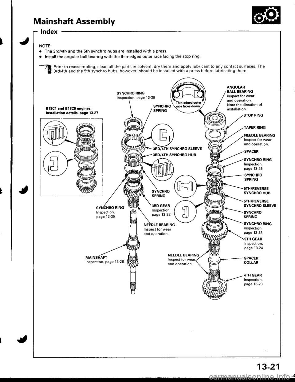
. The 3rd/4th and the 5th synchro hubs are installed with a press.
.Installtheangularball bearing with the thin-edged outer race facing the stop ring.
Prior to reassembling, clean all the parts in solvent, dry them and apply lubricant to any contact surfaces. The
3rdl4th and the 5th synchro hubs, however, should be installed with a press before lubricating lhem.
SYNCHRO RINGInspection, page 13-35
ANGULARBALL BEARINGInspect tor weatano oporaron,Note the direction ofinstallation.818C1 .nd 818CS ongin$:In3tallation dot ils, p.go 13-27
I
LSYNCHROSPRING
3RD GEARInspection,page 13-22
STOP RING
TAPEN RING
NEEDLE BEARINGInspect for wearano operaton,
SPACER
SYNCHRO RINGInspecton,page'13-35
SYNCHROSPRING
5TH/REVERSESYNCHRO HUB
sTH/REVEBSESYNCHRO SLEEVE
SYNCHROSPRING
SYNCHRO RINGrnspect|on,page 13-35
sTH GEARInspection,page 13-24
SPACERCOLLAR
4TH GEARInspect|on,page 13-23
BEARINGInspect for wearano operaaron.
NEEOLE BEARING
ano operal|on.
{
13-21
Page 388 of 1681
|'I
Mainshaft Assembly
Glearance Inspection
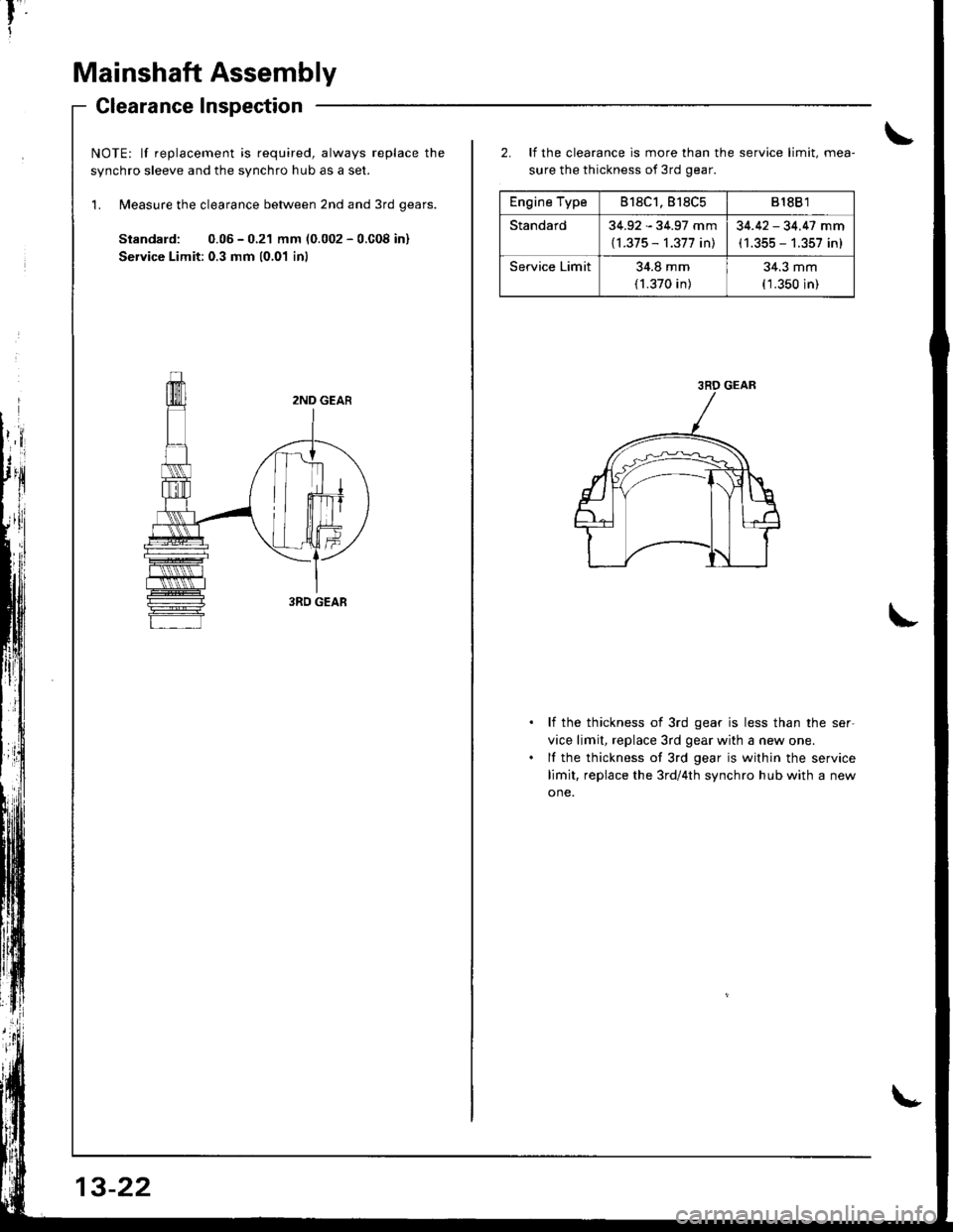
NOTE: lf replacement is required, always replace the
svnchro sleeve and the svnchro hub as a set.
'L Measure the clearance between 2nd and 3rd qears.
Standard: 0.05 - 0.21 mm (0.002 - 0.C08 in)
Service Limit: 0.3 mm 10,01 inl
13-22
Engine Type818C1.818C5818B 1
Standard34.92 - 34.97 mm
{l.375 - 1.377 in)
34.42 - 34.47 mm(1.355 - 1.357 in)
Service Limit34.8 mm
(1.370 in)
34.3 mm(1.350 in)
2. It the clearance is more than the service limit, mea-
sure the thickness of 3rd gear.
li the thickness of 3rd gear is less than the ser-
vice limit, replace 3rd gear with a new one.
lf the thickness of 3rd gear is within the service
limit, replace the 3rd/4th synchro hub with a new
one.
3RD GEAR
Page 389 of 1681
4.
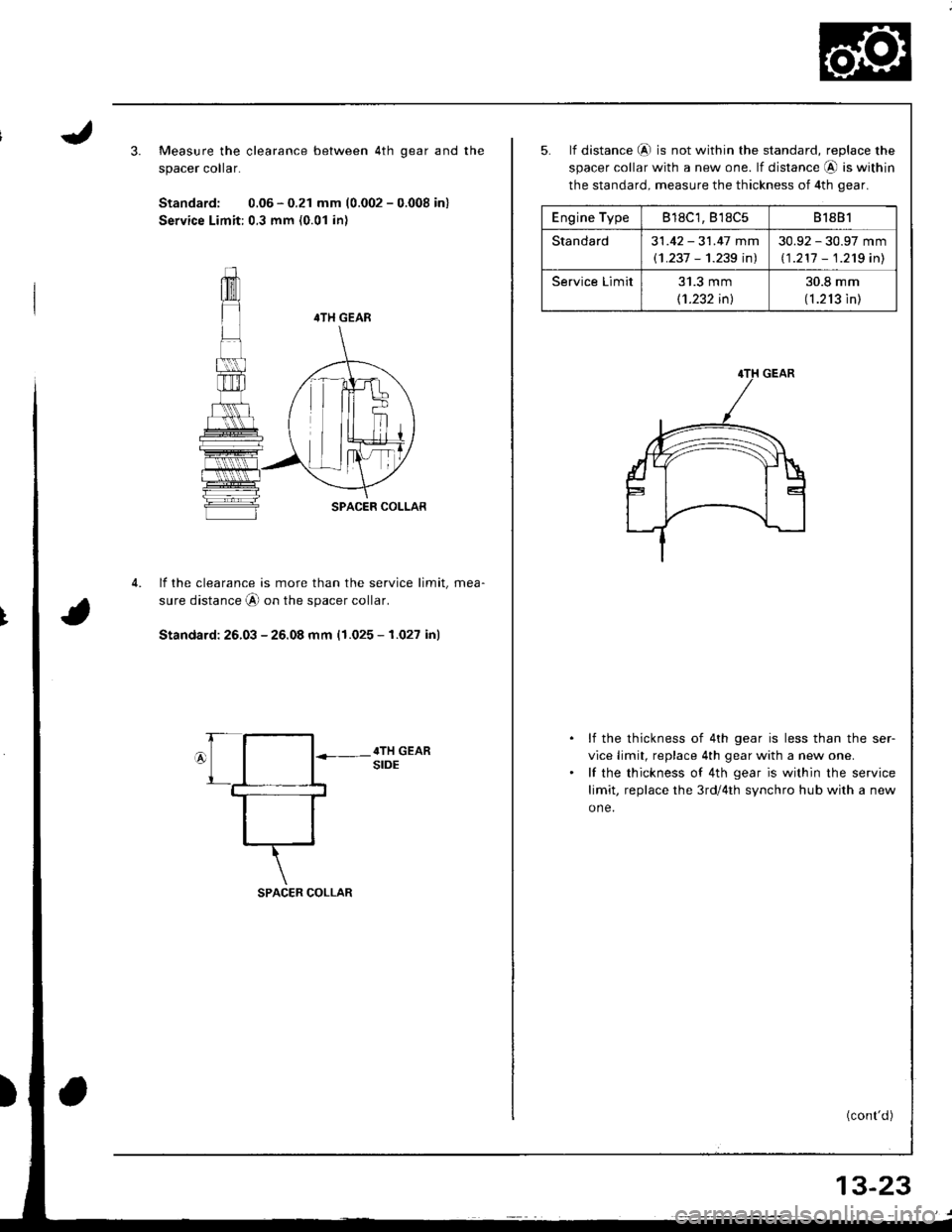
Measure the clearance between 4th qear and the
spacer colar.
Standard: 0.06 - 0.21 mm (0.002 - 0.008 in)
Service Limit:0.3 mm (0.01 in)
4TH GEAR
SPACER COLLAR
lf the clearance is more than the service limit, mea-
sure distance A on the spacer collar.
Standard: 26.03 - 25.08 mm (1.025 - 1.027 in)
SPACER COLLAR
Engine Type818C1, B'�l8C581881
Standard31 .42 - 31.47 mm
(1 .237 - 1.239 inl
30.92 - 30.97 mm
11 .211 - 1.2'tg inl
Service Limit31.3 mm
11.232 inl
30.8 mm
(1.213 in)
5. lf distance @ is not within the standard, replace the
spacer collar with a new one. lf distance @ is within
the standard, measure the thickness of 4th gear.
lf the thickness of 4th gear is less than the ser-
vice limit, replace 4th gear with a new one.
lf the thickness of 4th gear is within the service
limit, replace the 3rd/4th synchro hub with a new
one.
(cont'd)
13-23
Page 390 of 1681
Mainshaft Assembly
Clearance Inspection (cont'dl
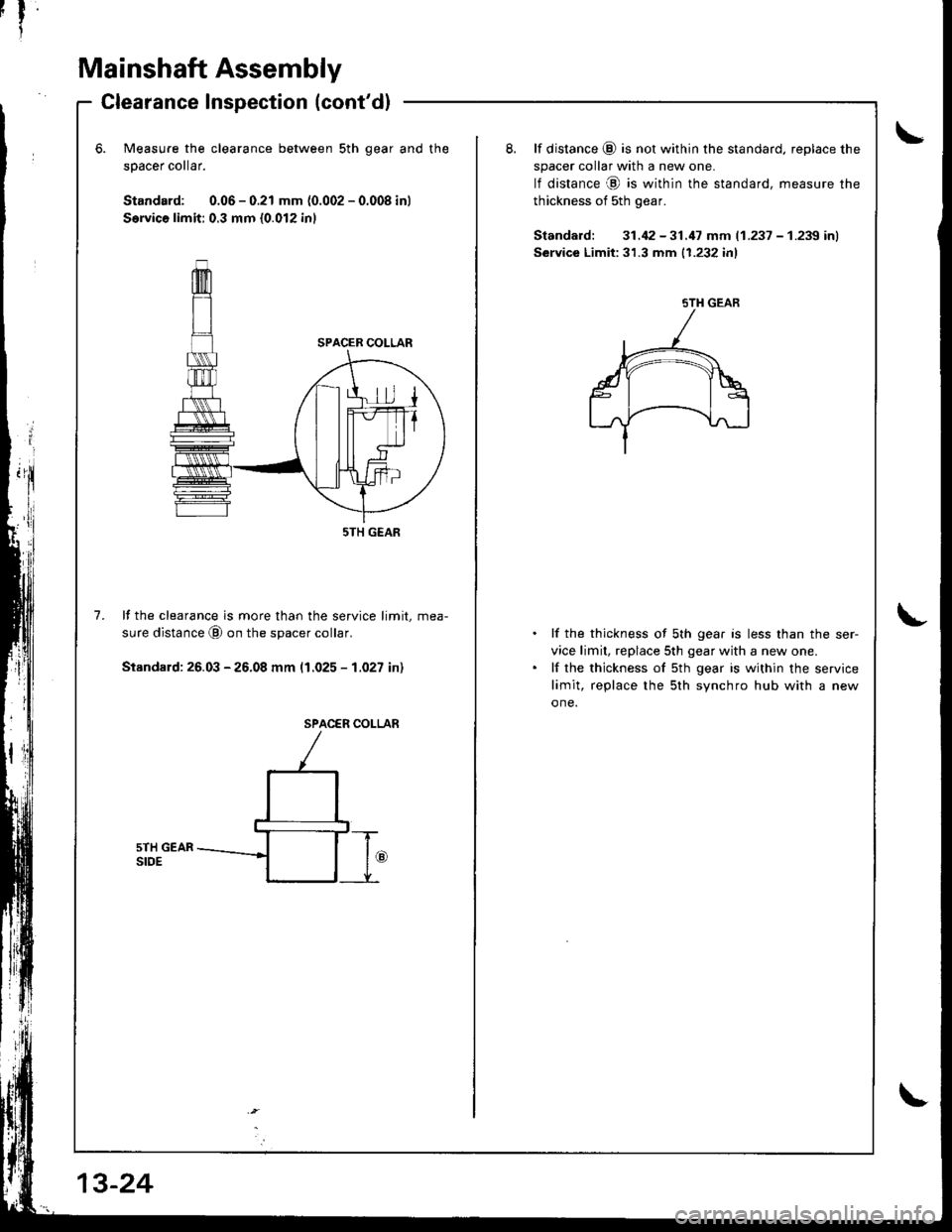
Measure the clearance between sth qear and
50acer collar.
Standard: 0.06 - 0.21 mm (0.002 - 0.008 in)
S€rvica limit: 0.3 mm {0.012 inl
the8. lf distance (9 is not within the standard, replace the
spacer collar with a new one.
lf distance @ is within the standard, measure the
thickness of sth gear.
Standard: 31.42 -31.17 mm (1.237 - 1.239 inl
Service Limit:31.3 mm {1.232 inl
7.lf the clearance is more than the service limit, mea-
sure distance @ on the spacer collar.
Stsndard: 26.03 - 26.08 mm (1.025 - 1.027 in)
lf the thickness of sth gear is less than the ser-
vice limit, replace 5th gear with a new one.
lf the thickness of sth gear is within the service
limit, replace the 5th svnchro hub with a new
one.
SPACER COI-LAR
sTH GEAR
5TH GEAR
Trending: audio, 18-8, radio, bulb, automatic transmission fluid, headlight bulb, check oil
