HONDA INTEGRA 1998 4.G Workshop Manual
Manufacturer: HONDA, Model Year: 1998, Model line: INTEGRA, Model: HONDA INTEGRA 1998 4.GPages: 1681, PDF Size: 54.22 MB
Page 441 of 1681
Description
Hydraulic Control (cont'd)
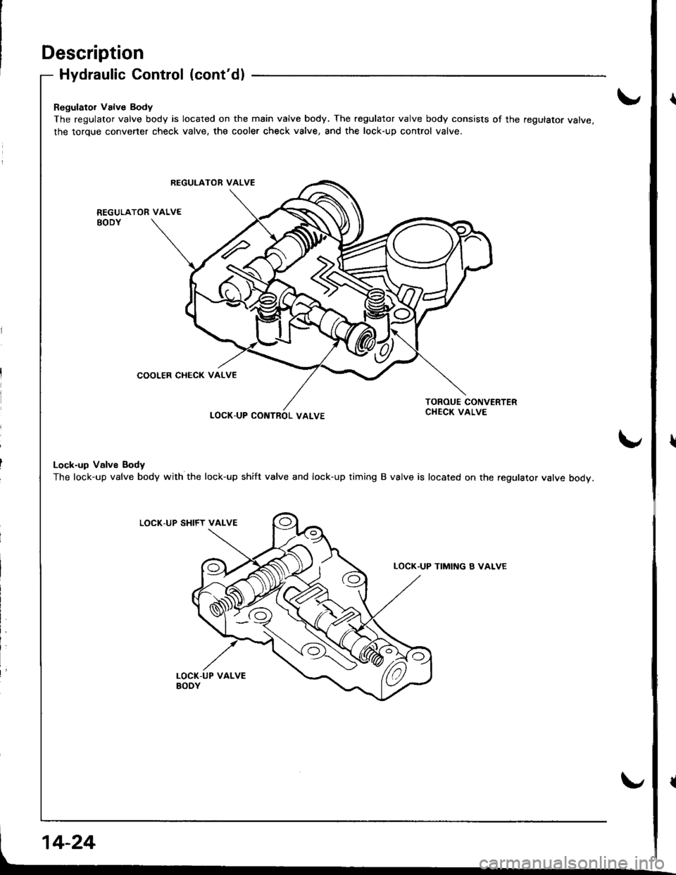
Regulator Valve Body
The regulator valve body is located on the main valve body. The regulator valve body consists of the regulator valve,
the torque converter check valve, the cooler check valve, and the lock-up control valve.
LOCK.UP CONTROL VALVE
Lock-up Valve Body
The lock-up valve body with the lock-up shift valve and lock-up timing B valve is located on the regulator valve body.
LOCK-UP SHIFY VALVE
TIMI[\'G B VALVE
REGUI-ATOR VALVE
COOLER CHECK VALVE
Page 442 of 1681
I
I
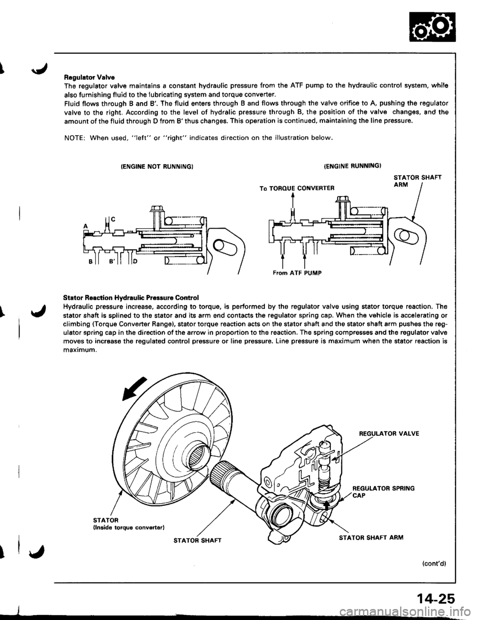
Rogulator Valve
The regulator valve maintains a constant hydraulic pressure from the ATF pump to the hydraulic control system. while
also furnishing fluid to the lubricating system and torque converter.
Fluid flows through B and B'. The fluid enters through B and flows through the valve orifice to A, pushing the regulator
valve to the right. According to the level of hydralic pressure through B. the position of the valv€ changes, and the
amount of the fluid through D from B' thus changes. This operation is continued, maintaining the line pressure.
NOTE: When used, "left" or "right" indicates direction on the illustration below.
{ENGINE NOT RUNNINGI{ENGINE RUNNINGI
STATOR SHAFT
Stator Reactior Hydrrulic Prcsrure Control
Hydraulic pressure incresse, according to torque, is performed by the regulator valve using stator torque reaction. The
stator shaft is splined to the stator and its arm end contacts the regulator spring cap. When the vehicle is accelerating or
climbing (Torque Converter Range), stator torque reaction acts on the stator shaft and the stator shaft arm pushes the reg-
ulator spring c8p in the direction of the srrow in proportion to the reaction. The spring compresses and the regulator valve
moves to incrsase the regulated conlrol pressure or line pressure. Line pressure is maximum when the stator reaction is
maximum.
TOR VALVE
{cont'dl
From ATF PUMP
I
STATOB SHAFTSTATOR SHAFT ARM
14-25
Page 443 of 1681
Description
Hydraulic Control (cont'dl
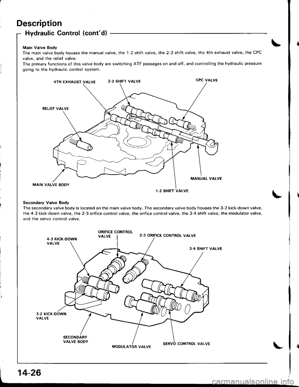
Main Valve Body
The main valve body hous€s the manual valve, the 1 2 shift valve, the 2-3 shilt valve, the 4th exhaust valve, the CPC
valve, and the reliel valve.
The primary {unctions of this valve body are switching ATF passages on and olf, and controlling the hydraulic pressure
going to the hydraulic control system.
4TH EXHAUST VALVE2-3 SHIFT VALVECPC VALVE
RELIEF VAI-VE
MANUAL VALVE
MAIN VALVE EODY
Secondary Valve Body
The secondary valve body is located on the main valve body. The secondary valve body houses the 3-2 kick-down valve,
the 4-3 kick-down valve, the 2-3 orifice control valve, the orifice control valve. the 3-4 shitt valve, the modulator valve,
and the servo control valve.
ORIFICE CONTROLVALVE2-3 oRtFtCE CONTROT_ VALVE
3-4 SHIFT VALVE
1-2 SHIFT VALVE
MOOULACONTROL VALVE
Page 444 of 1681
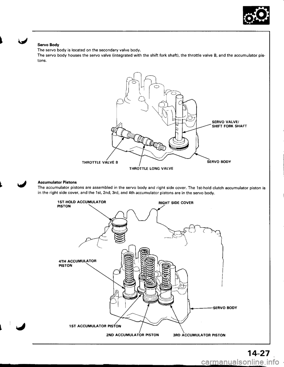
Servo Body
The servo body is located on the secondary valve body.
The servo body houses the servo valve (integrated with the shift fork shaft), the throttle valve B, and the accumulator pis-
tons.
THROTTLE
Accumulator Pistons
The accumulator pistons are assembled in the servo body and right side cover. The 1st-hold clutch accumulator piston is
in the right side cover, and the 1st,2nd,3rd, and 4th accumulator pistons are in the servo bodv.
lST.HOLD ACCUMULATORPISTON
lST ACCUMUI.ATOR
2ND ACCUMULA3RO ACCUMULATOR PISTON
THBOTTLE LONG VALVE
RIGHT SIDE COVER
14-27
Page 445 of 1681
Description
Hydraulic Flow
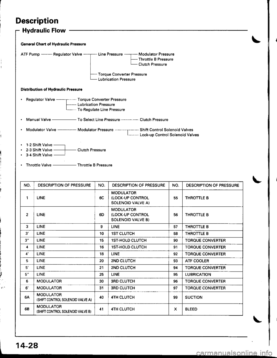
G€n6.al Chart of Hydraulic Pr6sure
ATF Pump - Regulator Valve
Distribution of Hydraulic Pressuro
Line Pressure -----r- Modulator Pressure
F-- Thronle B PressureL Clutch Pressure
Toroue Convener Pressure
Lubrication Pressure
. Regulator Valve ----; Torque Converter Prossure
f- Lubricaiion PrassureL To Regulate Line Pressure
Manual Valve - To Select Line Pressure - Clutch Pressure
. Modulator Valve Modulator Pressure ---- --I----- Shift Control Solenoid ValvosL- Lock-uD Control Solenoid Valves
. 1-2 Shift Valve -----l
. 2-3 Shift Valve ----f- Clutch Pressure. 3-4 Shift Valve ----------r
. Throttle Valve - Throttle B Pressure
NO,DESCRIPTION OF PRESSURENO.DESCRIPTION OF PR€SSURENO.DESCRIPTION OF PRESSURE
1LINE6C
MODULATOR(LOCK.UP CONTROL
SOLENOID VALVE A)
55THROTTLE B
LINE6D
MODULATOR(LOCK-UP CONTROL
SOLENOID VALVE B)
56THROTTLE B
LINEaLINETHROTTLE B
LINE101ST CLUTCH5dTHROTTLE B
LINE151ST-HOLD CLUTCH90TOROUE CONVERTER
4LINElST.HOLD CLUTCH91TOROUE CONVERTER
LINE18LINE92TOROUE CONVERTER
5LINE202ND CLUTCH93ATF COOLER
LINE212ND CLUTCH94TOROUE CONVERTER
5'LINE25LINELUBRICATION
6MODULATOR303RD CLUTCH96TOROUE CONVERTER
MODULATOR313RD CLUTCH97TOBOUE CONVERTER
64MODULATOR(SHIN CONTROLSOLENOIO VALVE A)404TH CLUTCHooSUCTION
6BMODULATOR(SHIFT CONTROT SOLENOID VATVE B)414TH CLUTCHXBLEED
Page 446 of 1681
I
I
I
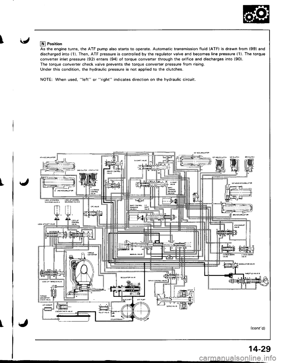
Llfl Position
As the engine turns, the ATF pump also starts to operate. Automatic transmission fluid (ATF) is drawn from (99) and
discharged into (1). Then, ATF pressure is controlled by the regulator valve and becomes line pressure (1). The torque
converter inlet pressure {92} enters (94) ol torque converter through the orilice and discharges into {9O).
The torque converter check valve prevents the torque converter pressure from rising.
Under this condition, the hydraulic pressure is not applied to the clutches.
NOTE: When used, "l€ft" or "right" indicates direction on the hydraulic circuit.
(cont'dl
14-29
Page 447 of 1681
Description
Hydraulic Flow (cont'dl
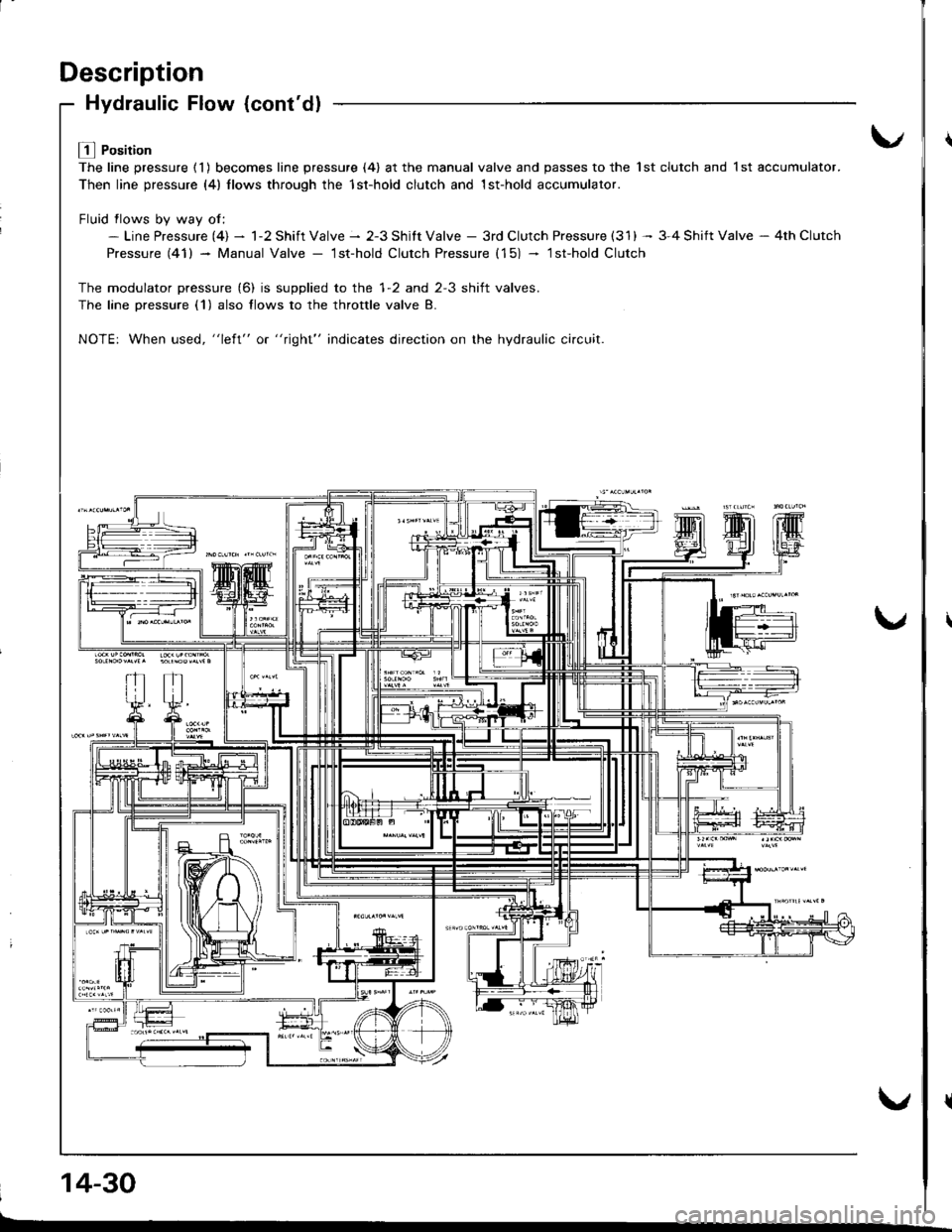
L! l Position
The line pressure ( 1 ) becomes line pressure (4) at the manual valve and passes to the 1st clutch and 1 st accumulator.
Then line pressure (4) llows through the 1st-hold clutch and 1st-hold accumulator.
Fluid flows bv wav of:- Line Pressure (4) - 1-2 Shift Valve - 2-3 Shitt Valve - 3rd Clutch Pressure (31) -- 3-4 Shift Valve - 4th Clutch
Pressure (41) - Manual Valve - lst-hold Clutch Pressure (15) - lsfhold Clutch
The modulator pressure (6) is supplied to the 1-2 and 2-3 shift valves.
The lane Dressure (1) also flows to the throttle valve B.
NOTE: When used, "left" or "right" indicates direction on the hydraulic ci.cuit.
14-30
Page 448 of 1681
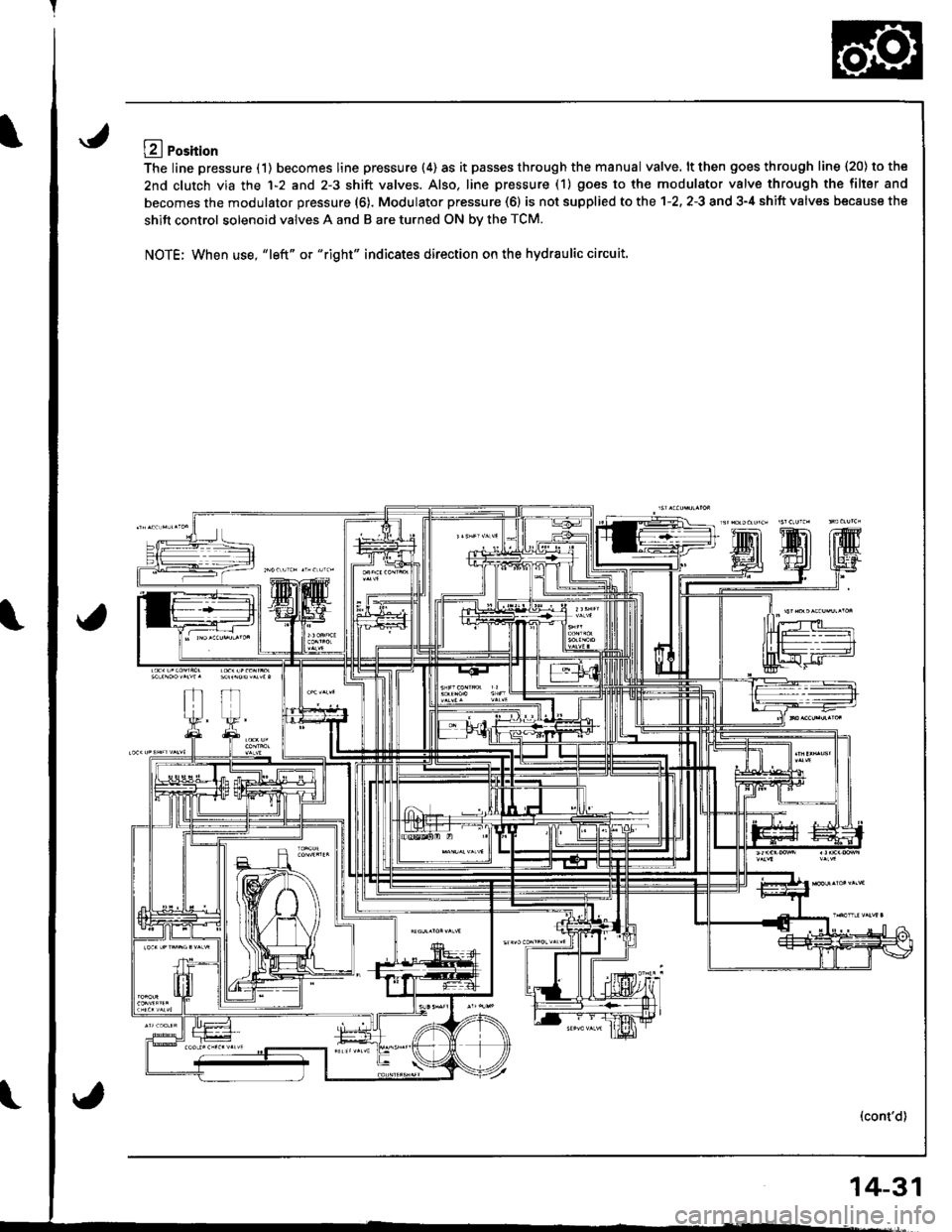
LA Position
The line pressure (1) becomes line pressure (4) as it passes through the manual valve. lt then goes through line 120) to the
2nd clutch via the 1-2 and 2-3 shift valves. Also. line pressure (1) goes to the modulator valve through the filler and
becomes the modulator pressure (6). Modulator pressure (6) is not supplied to the 1-2. 2-3 and 3-4 shift valves because the
shift control solenoid valves A and B are turned ON bv the TCM.
NOTE; When use, "left" or "right" indicates direction on the hydraulic circuit.
(cont'd)
14-31
Page 449 of 1681
Description
Hydraulic Flow {cont'dl
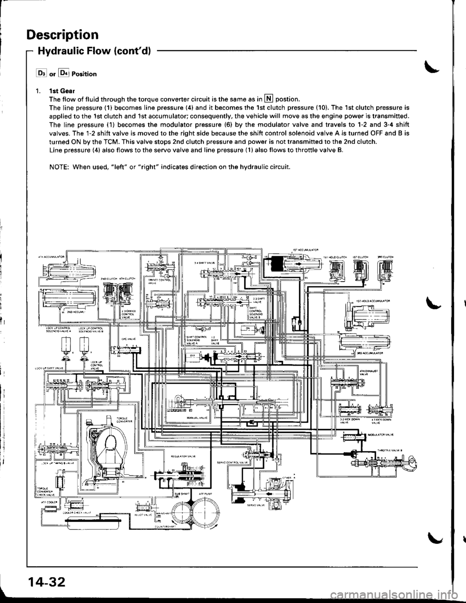
l ll or &j Position
1. lst Geal
The flow of fluid through the torque converter circuit is the same as in lll postion.
The line pressure (1) becomes line pressure (4) and it becomes the 1st clutch pressure (10). The 1st clutch pressure is
applied to the 1st clutch and 1st accumulator; consequently, the vehicle will move as the engine power is transmitted.
The line pressure (1) becomes the modulator pressure (6) by the modulator valve and travels to 1-2 and 3-4 shift
valves. The l-2 shift valve is moved to the right side because the shift control solenoid valve A is turned OFF and B is
turned ON by the TCM. This valve stops 2nd clutch pressure and power is not transmitted to the 2nd clutch.
Line pressure (4) also flows to the servo valve and line pressure (l ) also flows to throttle valve B.
NOTE: When used, "|eft" or "right" indicates direction on the hydraulic circuit.
fr
14-32
Page 450 of 1681
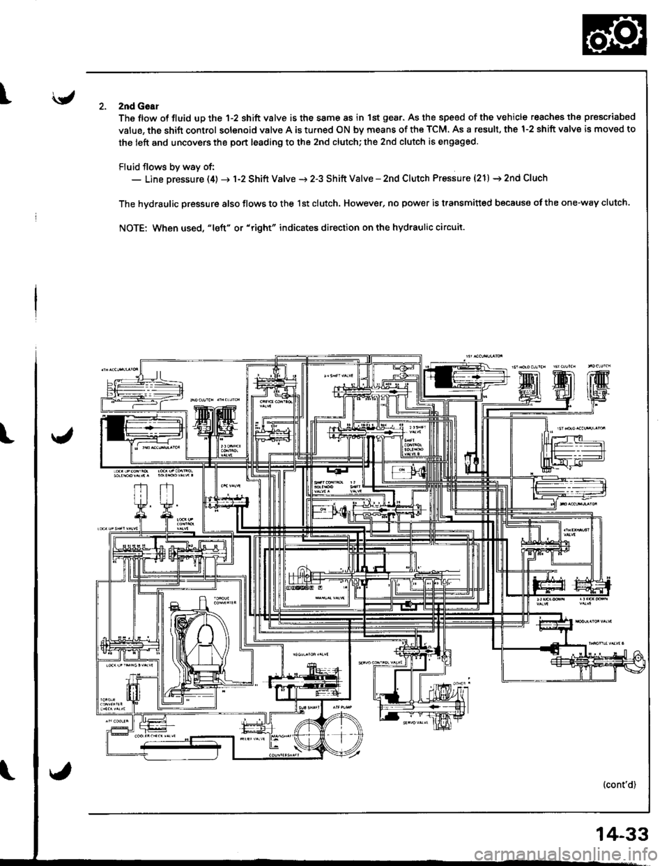
Iznd Goar
The ftow ot fluid up the 1-2 shift valve is the same 8s in 1st gear. As the speed of the vehicle reaches the prescriabed
value, the shift control solenoid valve A is turned ON by means of the TCM. As a result, the 1-2 shift valve is moved to
the left and uncovers the port leading to the 2nd clutch; the 2nd clutch is engaged.
Fluid flows by way of:- Line pressure (4) -r 1-2 Shift Valve i 2-3 Shift Valve - znd Clutch Pressure (21) i 2nd Cluch
The hydraulic pressure also flows to the lst clutch. However, no pow€r is transmitted because ofthe one-way clutch.
NOTE: When used, "Ieft" or "right" indicates ditection on the hydraulic circuit.
14-33