HONDA INTEGRA 1998 4.G Workshop Manual
Manufacturer: HONDA, Model Year: 1998, Model line: INTEGRA, Model: HONDA INTEGRA 1998 4.GPages: 1681, PDF Size: 54.22 MB
Page 451 of 1681
Description
Hydraulic Flow (cont'dl
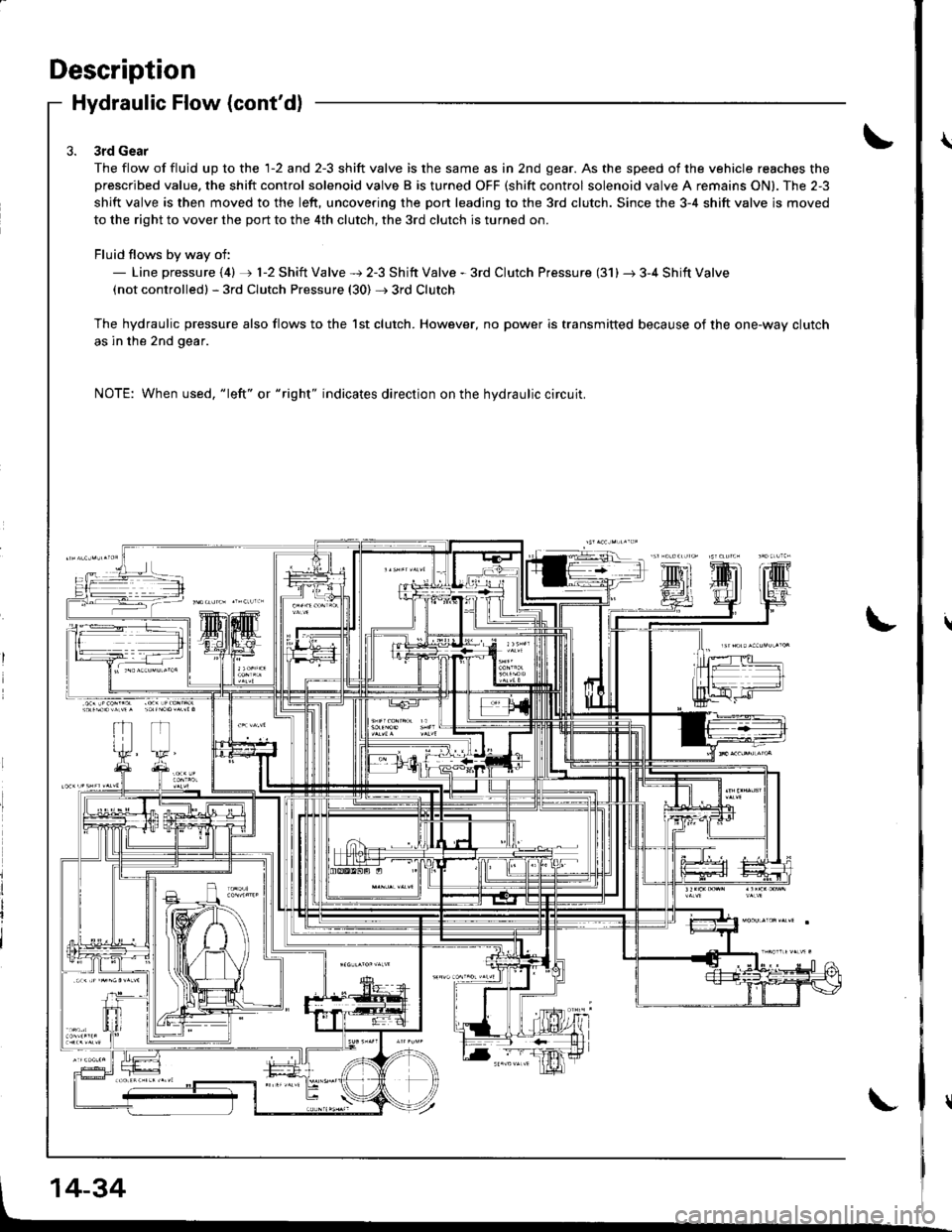
3rd Gear
The flow of fluid up to the 1-2 and 2-3 shift valve is the same as in 2nd gear. As the speed of the vehicle reaches theprescribed value. the shift control solenoid valve B is turned OFF (shift control solenoid valve A remains ON). The 2-3
shift valve is then moved to the left, uncovering the port leading to the 3rd clutch. Since the 3-4 shift valve is moved
to the right to vover the port to the 4th clutch, the 3rd clutch is turned on.
Fluid flows by way of:- Line pressure (4) rj) 1-2 Shift Valve + 2-3 Shift Valve - 3rd Clutch Pressure (31) r 3-4 Shift Valve(not controlledl - 3rd Clutch Pressure (30) + 3rd Clutch
The hydraulic pressure also flows to the lst clutch. However, no power is transmitted because of the one-way clutch
as in the 2nd gear.
NOTE: When used, "|eft" or "right" indicates direction on the hydraulic circuit.
14-34
Page 452 of 1681
Iq1 Position
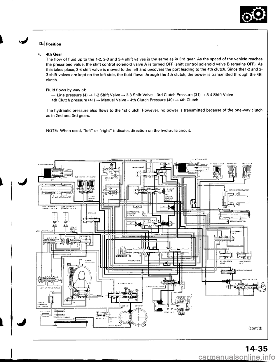
4. 4th Gear
The flow of fluid up to the 1-2, 2-3 and 3-4 shift valves is the same as in 3rd gear. As the speed of the vehicle reaches
the prescribed value, the shift control solenoid valve A is turned OFF (shift control solenoid valve B remains OFF). As
this takes place, 3-4 shitt valve is moved to the left and uncovers the port leading to the 4th clutch. Since thel-2 and 2-
3 shift valves are kept on the left side, the fluid flows through the 4th clutch; the power is transmitted through the 4th
clutch.
Fluid flows by way of:- Line pressure (4) + 1-2 Shift Valve ) 2-3 Shift Valve - 3rd Clutch Pressure (3'1) -t 3-4 Shift Valve -
4th Clutch pressure (41) + Manual Valve - 4th Clutch Pressure (40) + 4th Clutch
The hvdraulic pressure also flows to the 1st clutch, However, no power is transmitted because of the one-way clutch
as in 2nd and 3rd gears.
NOTE: When used, "1eft" or "right" indicates direction on the hydraulic circuit.
I
T(cont'd)
14-35
Page 453 of 1681
Description
Hydraulic Flow (cont'dl
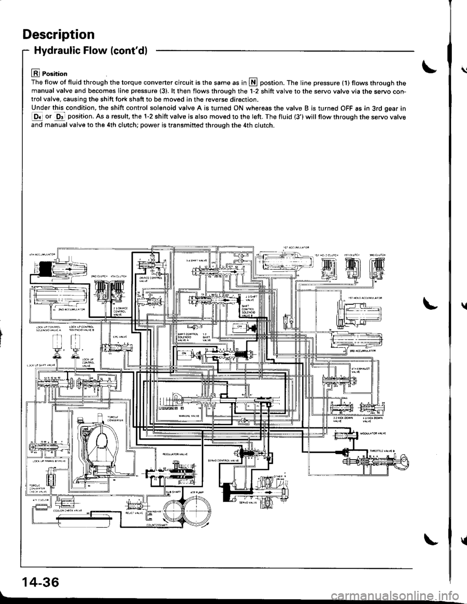
lll Position
The flow of fluid th.ough the torque converter circuit is the same as in S postion. The line pressure (1) tlows through themanual valve and becomes line pressure (3). lt then flows through the 1-2 shift valve to the servo valve via the servo con-trol valve, causing the shift fork shaft to be moved in the reverse direction.
Under this condition, the shift control solenoid valve A is turned ON whereas the valve B is turned OFF as in 3rd gear in
E ot O"- position. As a result. the 1-2 shift valve is also moved to the left. The fluid (3') will flow through tne servo varve
and manual valve to the 4th clutch; power is transmitted through the 4th clutch.
14-36
\l
\
{
{
Page 454 of 1681
![HONDA INTEGRA 1998 4.G Workshop Manual E Position
The flow of tluid through the torque converter circuit is the same as in L\l]position. The line pressure (1) becomes line
pressure (3) as it passes through the manual valve. Then line press HONDA INTEGRA 1998 4.G Workshop Manual E Position
The flow of tluid through the torque converter circuit is the same as in L\l]position. The line pressure (1) becomes line
pressure (3) as it passes through the manual valve. Then line press](/img/13/6069/w960_6069-453.png)
E Position
The flow of tluid through the torque converter circuit is the same as in L\l]position. The line pressure (1) becomes line
pressure (3) as it passes through the manual valve. Then line pressure (3) flows through the 1-2 shift valve to the servo
valve via the servo control valve, causing the shift fork shaft to be moved to the reverse position as in @ position.
However, the hydraulic pressure is not supplied to the clutches. Power is not transmitted.
NOTE: When used, "left" or "right" indicates direction on the hydraulic circuit.
14-37
Page 455 of 1681
Description
Lock-up System
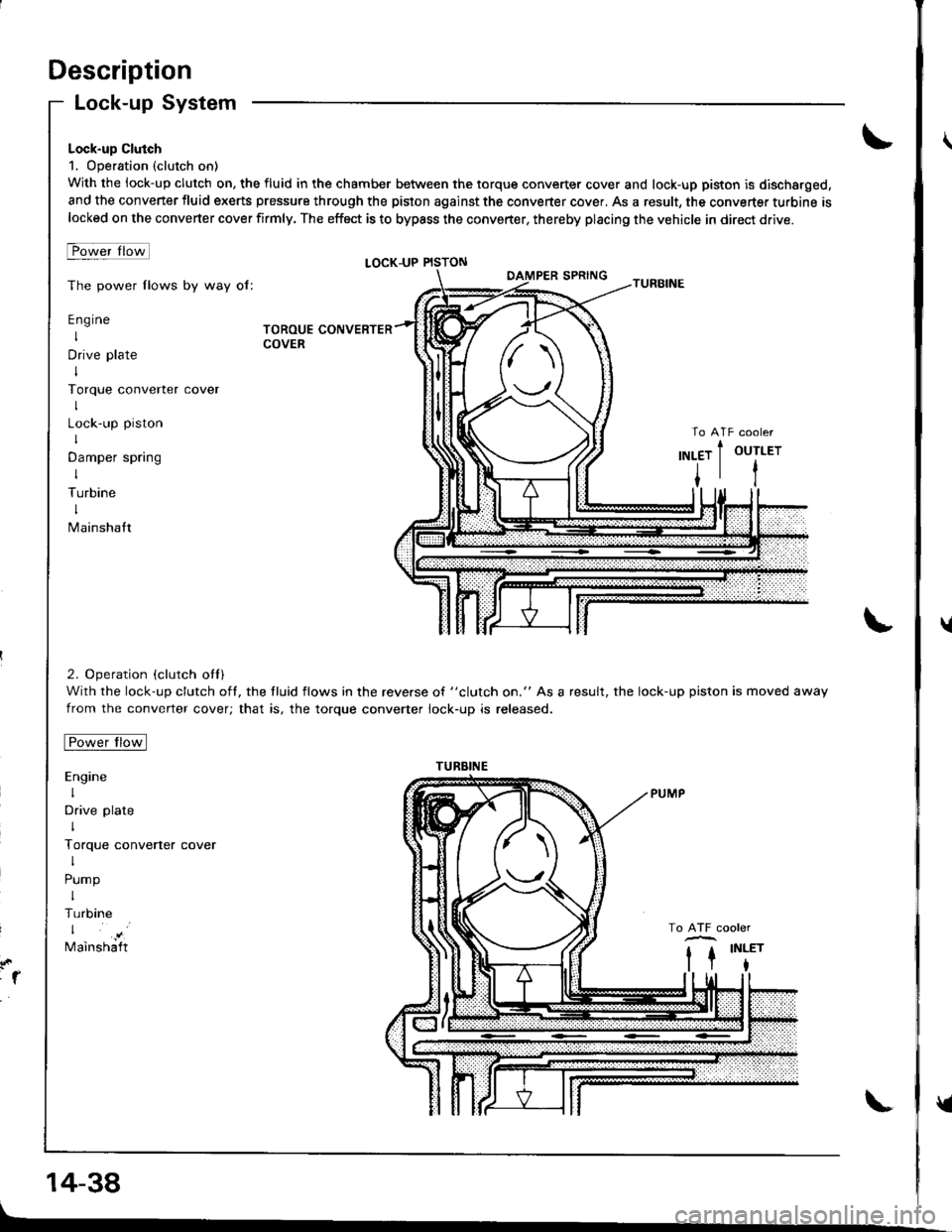
Lock-up Clutch
1. Operation (clutch on)
With the lock-up clutch on, the fluid in the chamber between the torque converter cover and lock-up piston is discharged,
and the converter fluid exerts pressure through the piston against the converter cover, As a result, the converter turbine islocked on the converter cover firmly. The effoct is to bypass the converter, thereby placing the vehicle in direct drive.
t-owerlrotl
The power flows by way of:
Engine
I
Drive plate
I
Torque converter
I
Lock-up piston
I
Damper spring
I
Turbine
I
Mainshatt
2. Operation (clutch otl)
With the lock-up clutch oft, the tluid flows in the reverse of "clutch on." As a result, the lock-up piston is moved away
from the converter cover; that is, the torque converter lock-up is released.
tro-wt rrotl
Engine
I
Drive plate
I
Torque converter cover
I
Pump
I
Turbine
Mainshaft
LOCK-UP PISTON
TOROUE CONVERTERCOVER
:1
14-38
TURBINE
tl
u
v
Page 456 of 1681
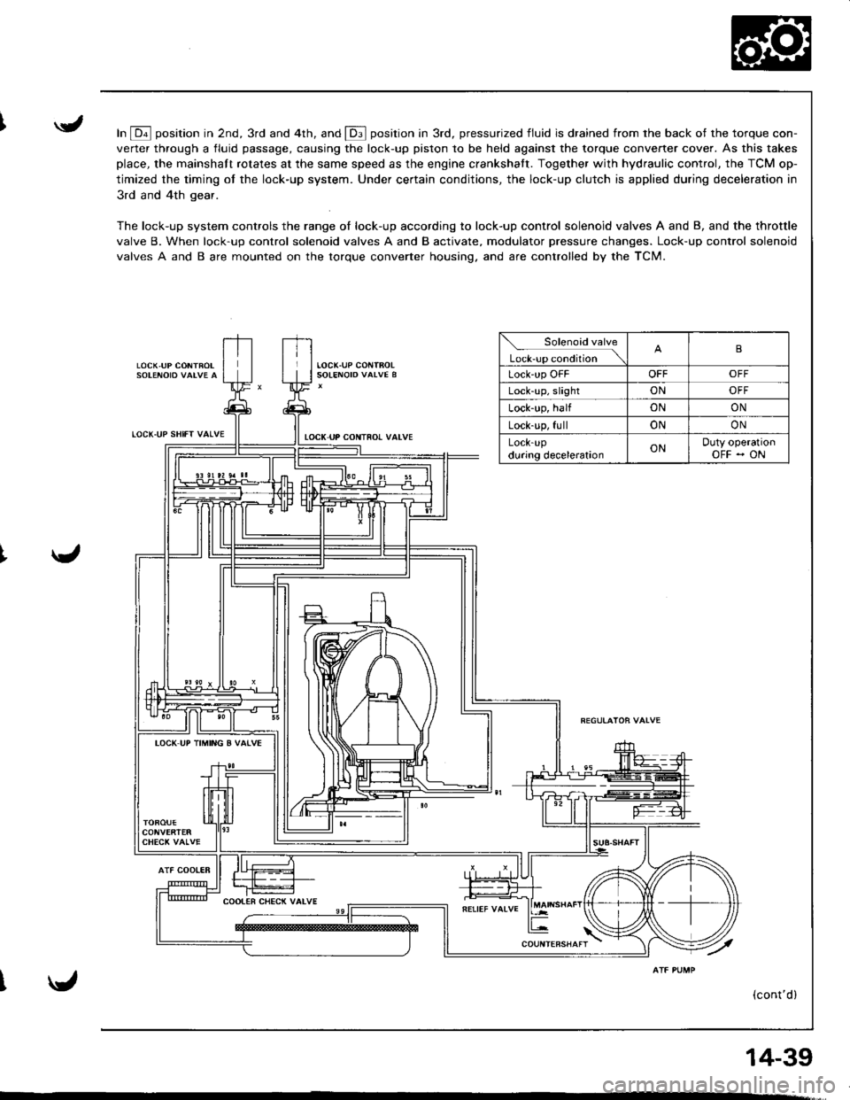
In E position in 2nd, 3rd and 4th, and E position in 3rd, pressurized fluid is drained from rhe back of the torque con-
verter through a fluid passage, causing the lock-up piston to be held against the torque converter cover. As this takes
place, the mainshaft rotates at the same speed as the engine crankshatt. Together with hydraulic control, the TCM op-
timized the timing of the lock-up system. Under certain conditions, the lock-up clutch is applied during deceleration in
3rd and 4th gear.
The lock-up system controls the range of lock-up according to lock-up control solenoid valves A and B, and the throttle
valve B. When lock-up control solenoid valves A and B activate, modulator pressure changes. Lock-up control solenoid
valves A and B are mounted on the torque converter housing. and are controlled by the TCM.
LOCK,UP CONTROL
LOCT.UP SHIfT VALVE
AlF COOIER
tocK uP coNTno! valvE
Solenoid valve
L*r""r "o.Jtio" \B
Lock'up OFFOFFOFF
Lock-up, slightONOFF
Lock-up, halfONON
Lock-up, fullONON
LOCK-Updu.ing decelerationONDuty operationOFF - ON
IOCK UP TIMING B VATVE
(cont'd)
14-39
Page 457 of 1681
Description
LOC(,UP SlllFT VATVE
Lock-up System (cont'd)
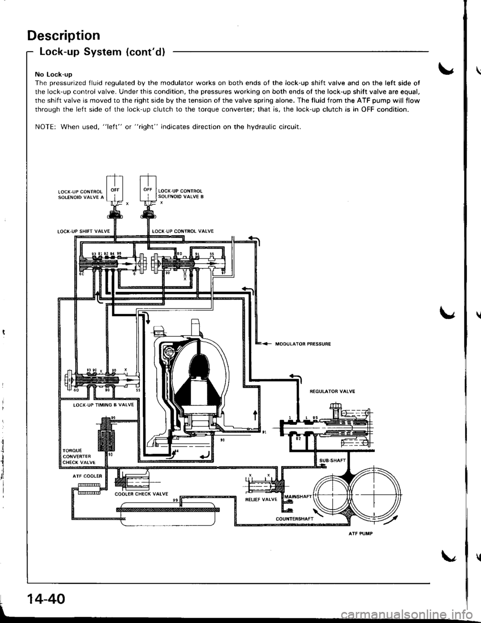
No Lock-ug
The pressurized fluid regulated by the modulator works on both ends of the lock-up shift valve and on the left side ot
the lock-up control valve. Under this condition, the pressures working on both ends of the lock-up shift valve are equal.
the shift valve is moved to the right side by the tension of the valve spring alone. The tluid from the ATF pump will llow
through the left side of the lock-up clutch to the torque converter; that is, the lock-up clutch is in OFF condition.
NOTE: When used, "left" or "right" indicates direction on the hydraulic circuit.
LOCX.UP CONTROI
LOCK.UP COITTFOT VATVE
MOOUTATOR PRESSURE
i
il
rl
I
IOCK IJP TIMING B VALVE
14-40
Page 458 of 1681
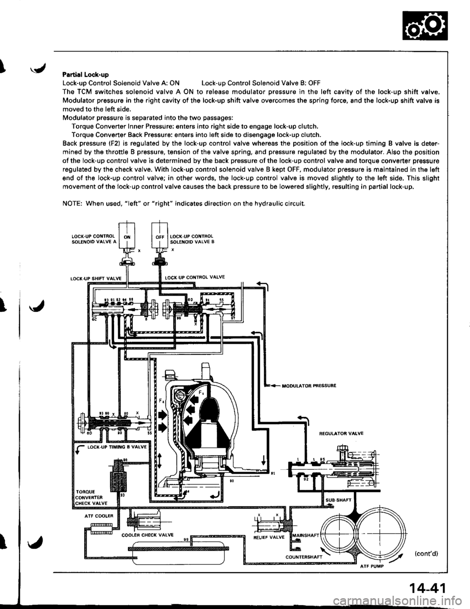
IPartial Lock-up
Lock-uo Control Solenoid Valve A: ONLock-uD Control Solenoid Valve B: OFF
The TCM switches solenoid valve A ON to release modulator Dressure in the left cavity of the lock-up shift valve.
Modulator pressure in the right cavity of the lock-up shift valve overcomes the spring force, 8nd the lock-up shift valve is
moved to the left side,
Modulator pressure is separated into the two passages:
Torque Converter Inner Pressure: enters into right side to engage lock-up clutch,
Torque Converter Back Pressure: enters into left side to disengage lock-up clutch.
Back prassure {F2) is regulated by the lock-up control valve whereas the position of the lock-up timing B valve is deter-
mined by the throttle B pressure, tension of the valve spring, and pressure regulated by the modulator. Also the position
of the lock-up control valve is determined by the back prossure of the lock-up control valve and torque converter pressure
regulated by the check valve. With lock-up control solenoid valve B kept OFF. modulator pressure is maintained in the left
end of the lock-up control valve; in other words, the lock-up control valve is moved slightly to the left side. This slight
movement of the lock-up control valve causes the back pressure to be lowered slightly, resulting in partial lock-up.
NOTE: When used, "|eft" or "right" indicates direction on the hydraulic circuit.
LOCK.UP GO TNOLSOLENOIO VAIVE A
TOCK-UP SHIFT VAIVELOCI( UP COI{TROL VAIVE
T
LOC(,UP IM TG g VALV€
MODULATOB PNESSUFE
14-41
Page 459 of 1681
Description
I,OCK UP SHIFT VALVE
Lock-up System (cont'dl
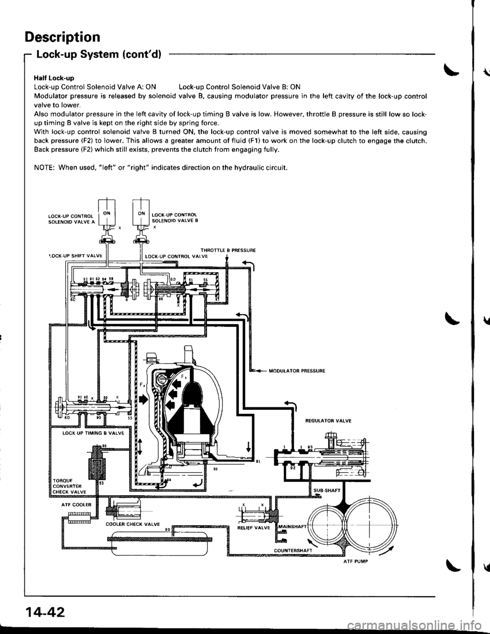
Halt Lock-up
Lock-up Control Solenoid Valve A: ONLock-up Control Solenoid Valve B: ON
Modulator pressure is released by solenoid valve B. causing modulator pressure in the left cavity of the lock-up control
valve to lower.
Also modulator pressure in the left cavity of lock-up timing B valve is low. However, throttle B pressure is still low so lock-
up timing B valve is kept on the right side by spring force.
With lock-up control solenoid valve B turned ON, the lock-up control valve is moved somewhat to the left side, causing
back pressure (F2) to lower. This allows a greater amount of fluid (F1) to work on the lock-up clutch to engage the clutch.
Back pressure (F2) which still exists, prevents the clutch from engaging fully.
NOTE: When used, "|eft" or "right" indicates direction on the hydraulic circuit.
LOCK.UP COI\ITBOL
THROITIE B PRESSUREIOCX UP COIITROL VALVE
MODULATOR PNESSURE
TOCK UP TIMING B VALVE
14-42
\
t
{
Page 460 of 1681
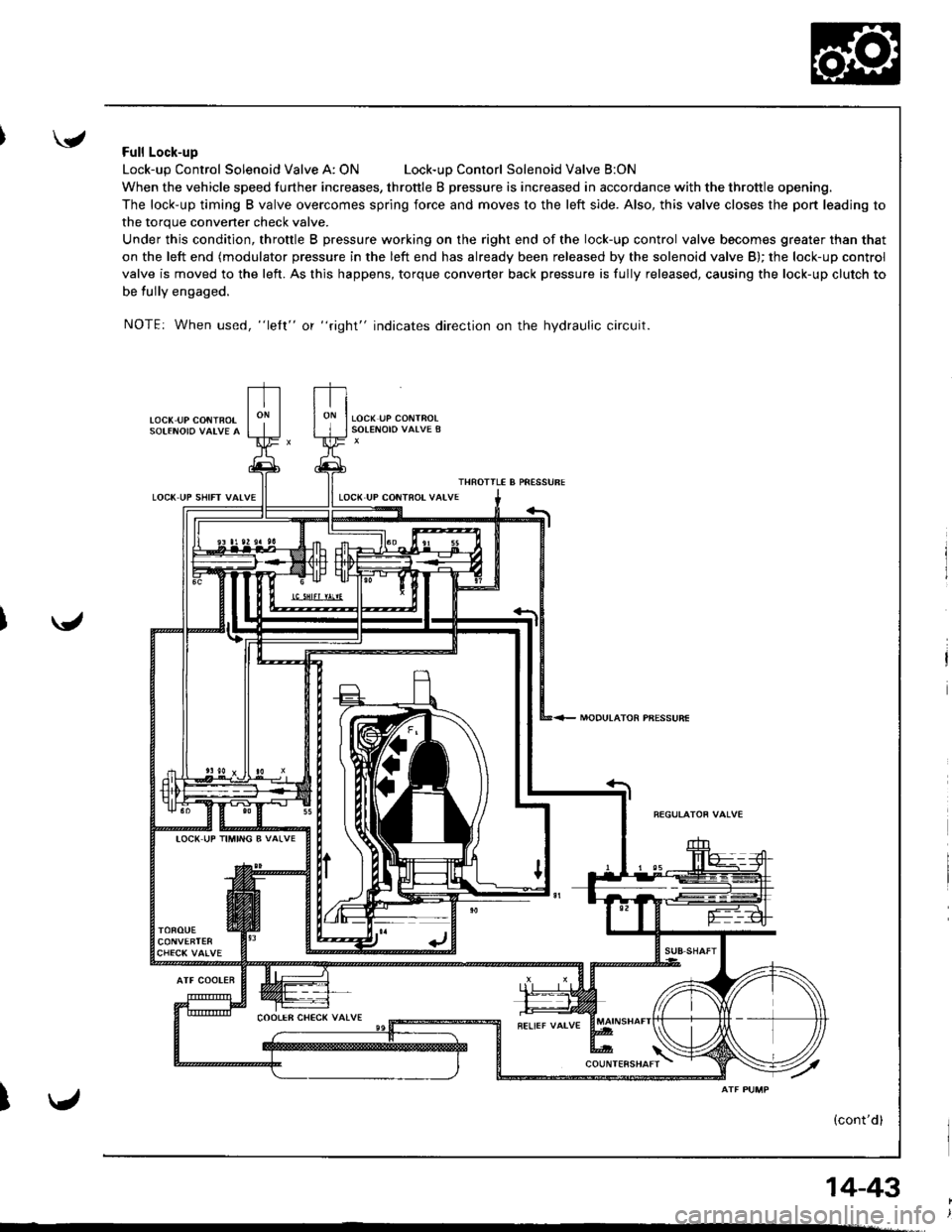
'Full Lock-up
Lock-up Control Solenoid Valve A: ONLock-uD Contorl Solenoid Valve B:ON
When the vehicle speed further increases, throttle B pressure is increased in accordance with the throttle opening.
The lock-up timing B valve overcomes spring force and moves to the left side. Also, this valve closes the port leading to
the torque convener check valve.
Under this condition, throttle B pressure working on the right end of the lock-up control valve becomes greater than that
on the left end (modulator pressure in the left end has already been released by the solenoid valve B); the lock-up control
valve is moved to the left. As this happens, torque converter back pressure is fully released, causing the lock-up clutch to
be tully engaged.
NOTE: When used, "lelt" or "right" indicates direction on the hydraulic circuit.
LOC( UP CONiBOT
LOCK UP SHIFT VAIVE
MODULATOR PBESSURE
ATF COOLER
I
IOC( UP TIMING B VALVE
14-43