HONDA INTEGRA 1998 4.G Workshop Manual
Manufacturer: HONDA, Model Year: 1998, Model line: INTEGRA, Model: HONDA INTEGRA 1998 4.GPages: 1681, PDF Size: 54.22 MB
Page 491 of 1681
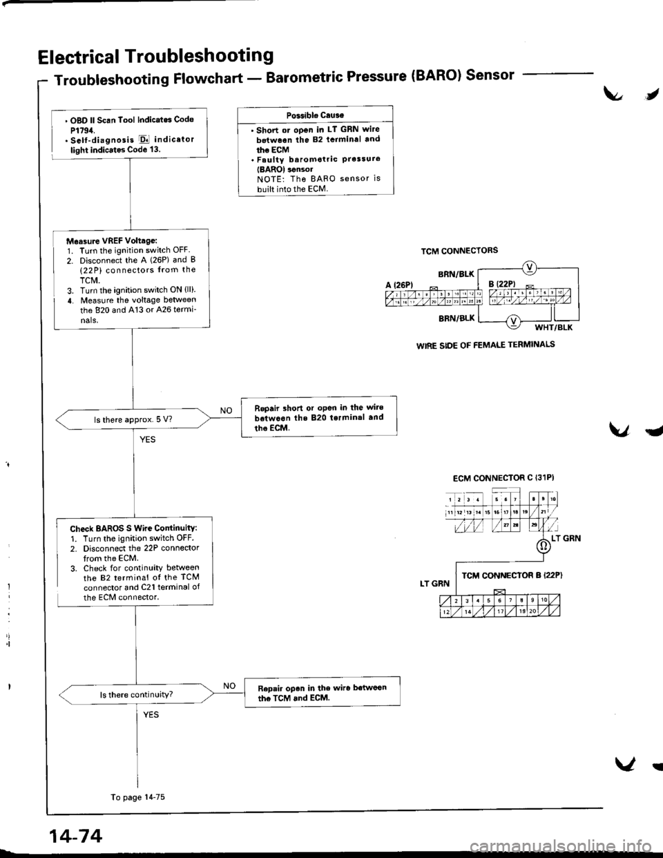
Electrical Troubleshooting
Troubleshooting Flowchart - Barometric Pressure (BARO) Sensor
t\l,
l
'|
. OBD ll Scan Tool lndicatos Code
P1794.. Self-diagnosis El indicator
light indicatos Code 13.
Check BAROS S Wire ContinuitY:1. Turn the ignition switch OFF.
2. Disconnect the 22P connedortrom the ECM.3. Check for continuity betweenthe 82 terminal ot the TCM
connector and C21 terminal of
the ECM connector.
PGsible cau3€
' Short ot oDen in LT GRN wite
betwoen the 82 lcrminal and
ihe ECM. Faulty baromotric PrelsureIBAROI ignsolNOTE: Tho BAFO sensor is
built into the ECM.
VqJ
WIRE SIDE OF FEMALE TERMINALS
Measure VREF Volttge:1. Turn the ignition switch OFF.
2. Disconnect the A (26P) and B(22 P) connectors from the
TCM.3. Turn the ignition switch ON {ll}.
4. Measure the voltage between
the 820 and 413 or 426 termi-
nals,
Repair shon or oPen in the wite
betwcon the 820 tsrminal and
tho EcM.ls there approx.5 V?
Repair open in the wiro betwoon
the TcM and ECM.ls there continuity?
To page 14-75
14-74
V!
Page 492 of 1681
v
u
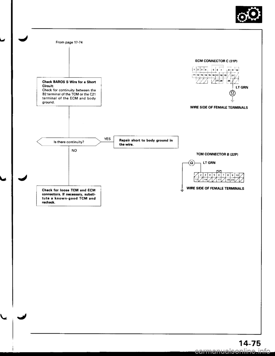
From page 17-74
Check BAROS S Wiro tor a ShortCircuh:Check for continuity between the82 terminal ofthe TCM or the C21terminal ot the ECM and bodyground.
Ch.ck {or loose TCM and ECMconnoctots. lf n€cessary, sub3ti-tut6 a known-good TCM androchock.
WIRE SIDE OF FEMALE TERMINALS
TCM CONNECTOR B {22PI
WIRE SIDE OF FEMALE TERMINALS
14-75
Page 493 of 1681
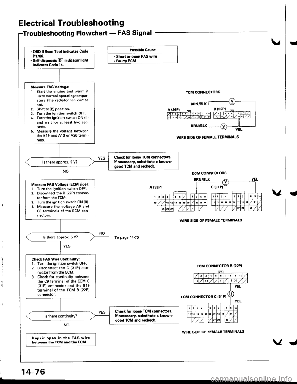
. OBD ll Scan Tool indicatcs CodeP1786.. Soff-diagnGis E indicrtor lightindicat6 Codo '1,0.
M6a3ure FAS Vottago:1. Start the engine and warm itup to normal operatang temPer_6ture (the radiator fan comeson).2. shift to E position.
3. Turn the ignition switch OFF.4. Turn the ignition switch ON (ll)
and wait lor at least two sec-onds.5. Measlre the voltage betweenthe 819 and A13 or A26 termi-nals.
Chsck for loo3r TCM connactot!.lf necoslary, lubsihuto a known.good TCM rnd r.chrck,ls there approx. 5 V?
M6asuro FAs vohagoIECM sidol:1. Turn the ignition switch OFF.
2. Disconnect the B (22P) connec-tor lrom the TCM.3. Turn the ignition switch ON (ll).
4. Measure the voltage Ag andC9 terminals of tho ECM con-nectors.
ls there approx. 5 V?
Chock for loore TCM connectoE.lf noceilary, subrtitula a known-good ICM rnd rcchock.
Repair opon in the FAS wircb€(we€n the TCM snd ths ECM.
Electrical Troubleshooting
Troubleshooting Flowchart - FAS Signal
vU
PG.iblo Cru!.
. Short o. opon FAS wira. Feoltv ECM
To page 14-75
TCM CONNECTORS
WIRE SIDE OF FEMALE TERMINALS
WIRE SIDE OF FEMAI.T TEBMINAI-S
WIRE SIDE OF FEMALE TERMINALS
a
,i,I
Chock FAS Wiro Continuity:1. Turn the ignition switch OFF.2. Disconnect the C (31P) con-nector lrom the ECM.3. Check lor continuity betweenthe C9 terminal of the ECM C(31P) connector and the 819terminal of the TCM B (22P)
14-76
ECM CONNECTORS
ECM CONNECTOR C I31P}
Page 494 of 1681
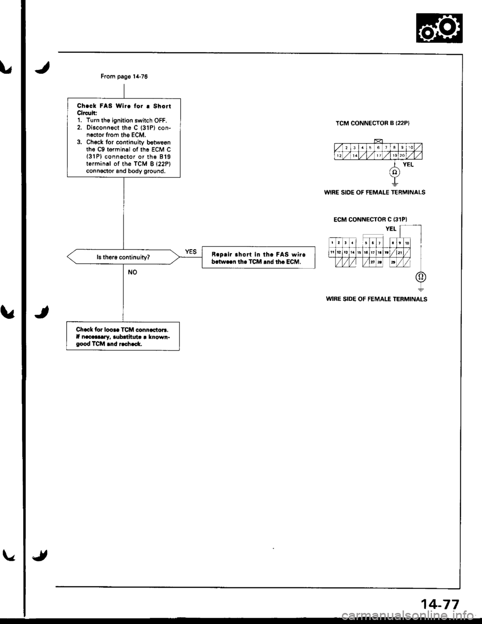
From pag€ 14-76
Ch.ck FAS Wir! for I ShoitClrc!hr1. Turn th6 ignition swilch OFF.2. Disconnect the C (31P) con-n€ctor from tho ECM.3. Chock for continuiv b€tweonth€ c9 torminal of th6 EcM c(3'lP) conn6ctor or the 819torminal of th€ fcM B l22Plconnoctor and body ground,
B.pllr rhort in th. FAS wirob.tw..n th. TCM .nd th. ECM.
Chack tor looaa TCM connactora.lf nacaaary, aubatltuta I known.good TCM .nd rach..k.
TCM CONNECTOR B {22P}
WIRE SIDE OF FEMALE TERMINALS
ECM CONNECTOR C {31PI
WIRE SIDE OF FEMALE TERMINALS
14-77
Page 495 of 1681
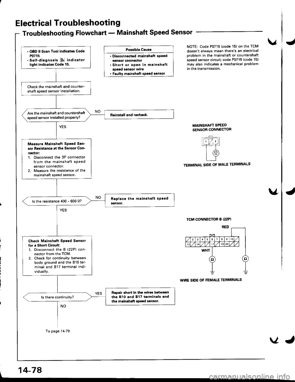
Electrical Troubleshootin g
Troubleshooting Flowchart - Mainshaft Speed Sensor
Po3aiblo causo
' Diaconnocted mrin3haft spocd30nsor connoctot. Short or open in mainshsttsoeod senSot wito. Faulty main3halt spood 3€n3ol
vNOTE: Code P0715 (code '15) on the TCM
doesn't always mean there's an electrical
oroblem in the mainshaft or countershaftspeed sensor circuit; code P0715 (code l5)
may also indicates a mechanical problem
in the lransmission.
MAINSHAFT SPEEDSENSOR CONNECTOR
TERMINAL SIDE OF MALE TERMINALS
TCM CONNECTOR B (22P)
WIRE SIDE OF FEMALE TERMINALS
\4
' OBD ll Sc.n Tool indicrt6 Codo
P0715' self-diagnosis El indicalorlight indicatos Code 15.
Check the mainshatt and counler-shaft soeed sensor installation.
Are the mainshaft and countershaltspeed sensor installed properly?
M6asure Mainshtft Spood Son'
sor Rgsi5tanco at ths Sonsol Con-
nec'tor:'t. Disconnect the 3P connectorIrom th6 mainshatt speedsensor connedor,2. Measure the rcsistance of themainshaft speed sensor.
ls the resistance 400 - 600 o?
Chock Mainshaft Speed Son3orfor a Short Circuh:l. Disconnect the B (22P) con-nector lrom the TCM.2. Check lor continuity betlveenbody ground and the 810 ter'
minal and 817 terminal indi-
vidually.
Repair 3hort in tha wi?es bttwo€ntho 810 lnd Bt? terminal3.ndtha mainshltt spaed sonaot.
To page 14-79
, 14-74
VJ
Page 496 of 1681
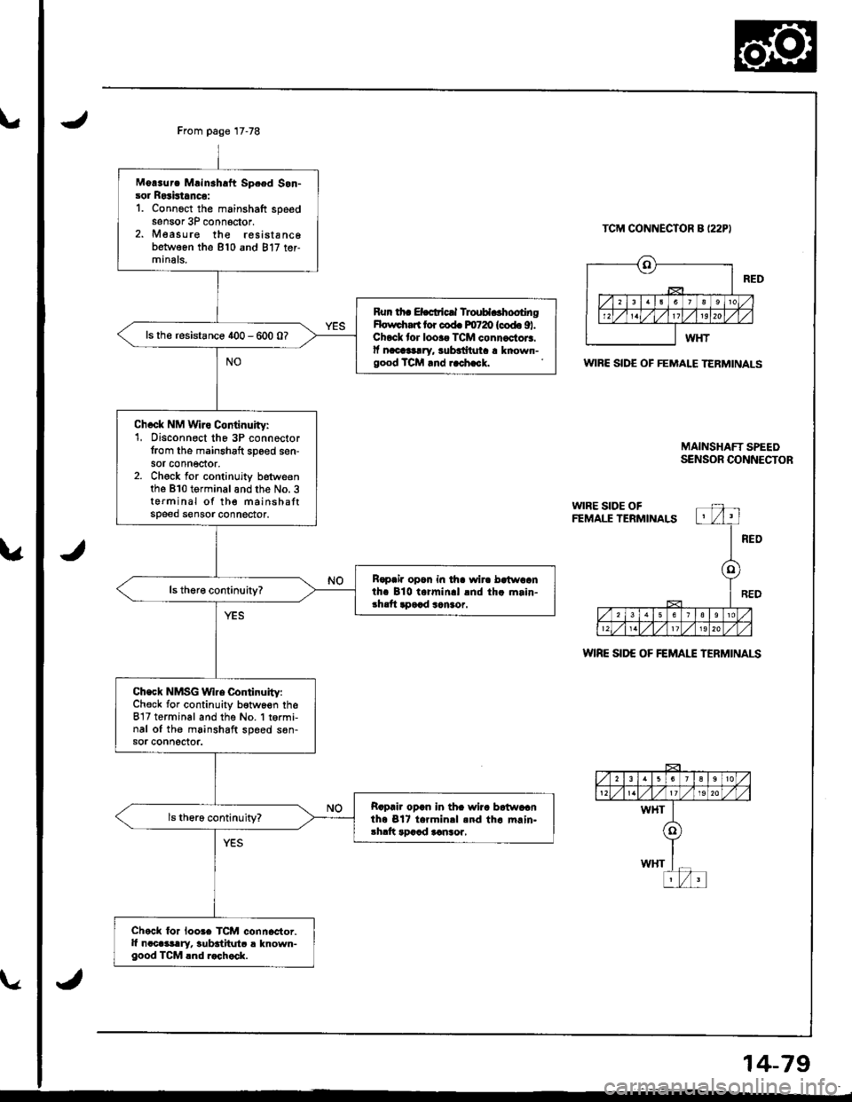
From page 17-78
Mo!3urc Mrinahaft Spced Son-sor Rosistrnco:1. Connoct the mainshaft speedsensor 3P conn6ctor.2. Measure the resista nc6between the 810 and 817 ter-minals.
Run th. ELcticrl TlouH..hootingHolrrdrart lor cod. m720 (codo 91.Chock lor looaa TCM connactor3.lf nacllg!ry, $badtuta a known-good TCM rnd i.ch.ck.
ls the resistance 400 - 600 0?
Ch.ck NM Wiro Continuity:1, Disconnect the 3P connector{rom the mainshaft sp6ed sen-sor connector,2. Check for continujty betweenthe B10 terminalandthe No. 3terminal of the mainshattspeed sensor connector.
R€paia opon in tha wir. bctwoanth. 810 t.rmin.l lnd th. m.in-3hrft apaad sanaor.
Check NMSG Wl.e Continuity:Check for continuity b€twoen theB'17 terminal and the No. 1 t6rmi,nal oI the mainshaft speed s6n-sor connector.
Rapair opan in thc wiia batwacnth6 Bl7 t.rmin.l .nd th. m.ln.3hdt rDaad aansor,
Chock lor loo3e TCM connactor.It n.cGslry, $bititutc ! known-good TCM lnd r.chock.
TCM CONNECTOR B I22PI
WIBE SIDE OF FEMALE TERMINALS
WIRE SID€ OF FEMAI"E TERMINALS
MAINSHAFT SPEEOSENSOR CONNECTOR
14-79
Page 497 of 1681
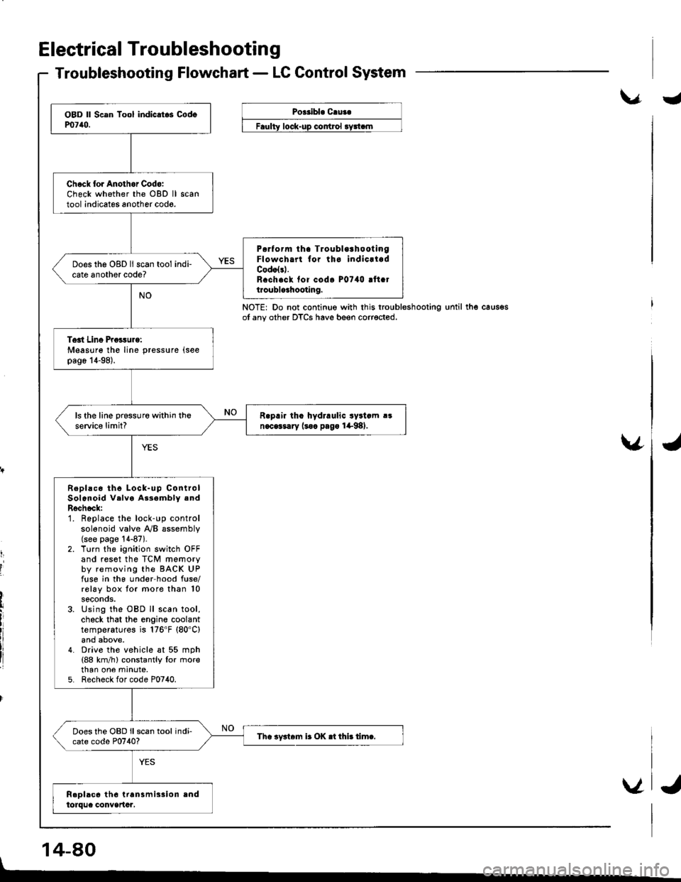
Electrical Troubleshootin g
Troubleshooting Flowchart - LC Control System
\.r.Poeribl. C.ua.
control
NOTE: Do not continue with this troubleshootingot any other DTCS have beeo corrected.until thg caus€s
v
t,
I
'I
14-80
Chock lor Anothor Cod6:Check whether the OBD lltool indicates another codo.
P6rform tha TroublorhootingFlowcha for tho indicrladCodolsl.R.ch.ck fof codo P0740 !ft.tt.oublo3hooting.
Does the OBD ll scan tool indi-cate another code?
Tost Line Proisurg:Measure the line pressure (see
pag6 14-98).
R.prir tho hydraulic syltcm !!n.cGsary (soc pago 1+98).ls the line prsssure within theservic€ limit?
Repl!c6 th6 Lock-up ControlSolenoid Velva As3ambly .ndRschock:1. Replace the lock-up controlsolenoid valve y'y'B assembly(see page '!4-87).
2. Turn the ignition switch OFFand reset the TCM memoryby removing the BACK UPfuse in the und€r-hood fuse/rolay box tor more than 10seconos.3. Using the OBD ll scan tool,check that the engine coolanttemperatures is 176'F (80'C)
4. Drive the vehicle at 55 mph(88 km/h) constantly lor rnorethan one mrnute,5. Recheck for code P0740.
Does the OBD ll scan tool indi-cate codo P0740?Tha iy3t6m ir OK .t thi! timc.
V
I
J
Page 498 of 1681
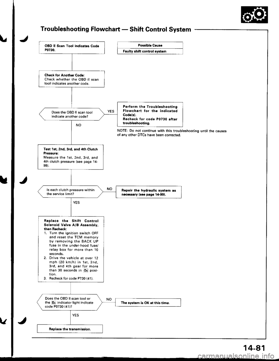
Troubleshooting Flowchart - Shaft Control System
NOTE: Do not continue with this troubleshootlng until the causesof any other DTCS have been corrected.
Chock foi Another Code:Check whether the OBD ll scantool indicates another code.
Psrtorm tho Tioubla3hootingFlowch.rt fo. th. indicatodCodcl.l.Rechsck tor code P0730 attoltroublolhooting.
Does the OBD ll scan toolindicate anothor code?
Tost 1st, 2nd, 3rd, and 4th ClutchProssuro:Measure the 1st,2nd,3rd, and4th clutch pressure (see page 14-
ls each clutch pressure withinthe service limit?R.p!ir lhG hydraulic ry3t.m ranac.3!.ry l3€e pago 1+991.
Roplace the Shilt ContiolSolonoid Valve A/B Assombly,thon Recheck:1. Turn the ignition switch OFFand reset the TCM memoryby removing the BACK UPfuse in the under-hood fuse/relay box for more than '10
seconds.2. Orive the vehicle at over 12mph (20 km/h) in lst,2nd,3rd, and 4th gear for morethan 30 seconds in E posi-tion.3, Recheck for code P730 (41).
Does the OBD llscan toolorthe E indicator light indicatecode P0730 (4'1)?Tho systom is OX etthi3 timo.
Poitible C.uBe
F""lty "hlft ".^t..t ",/"t".
Page 499 of 1681
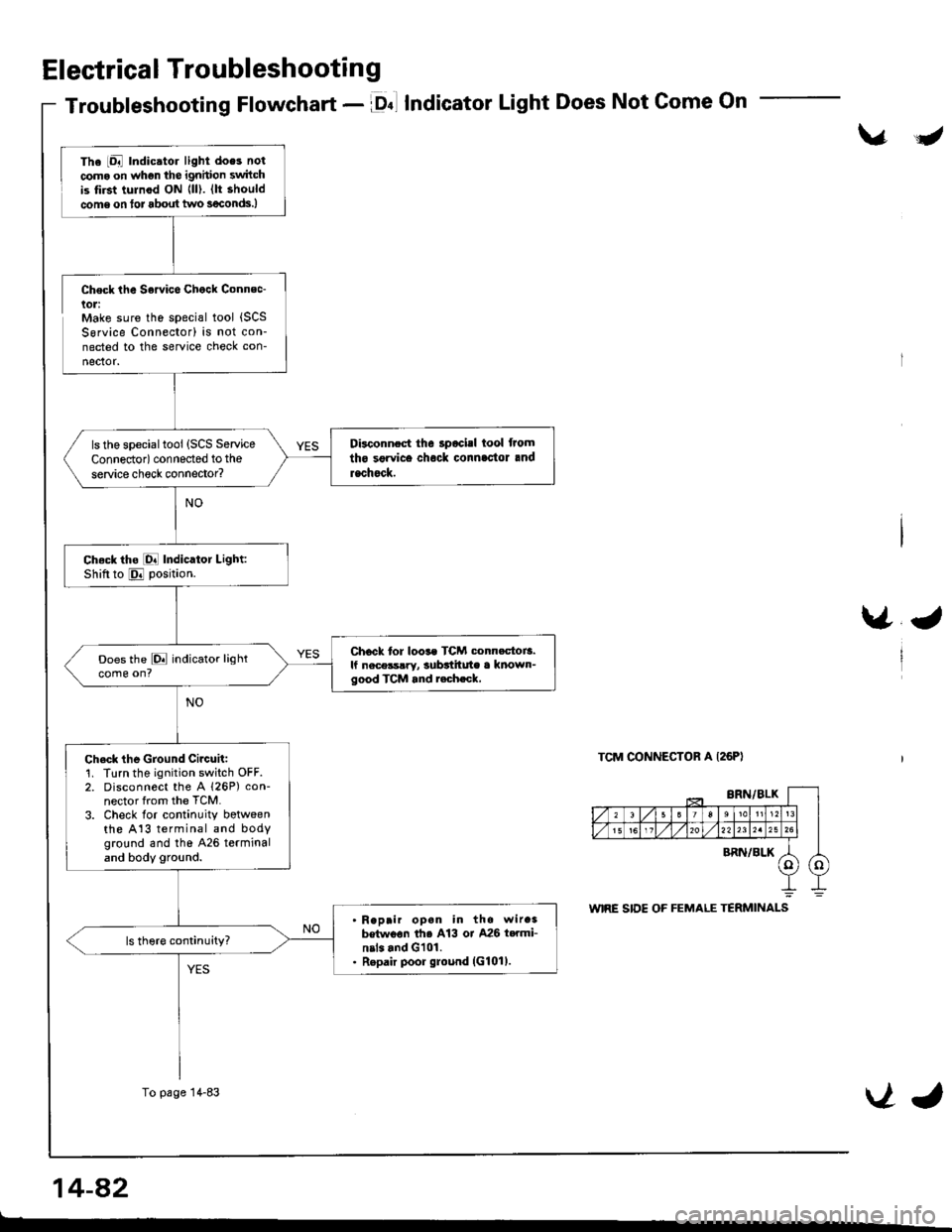
Electrical Troubleshooting
Troubleshooting Flowchart - lDnl IndicatorLight Does Not Come On
\/J
Check the Sowice Chock Connec-lol:Make sure the special tool {SCSSorvice Connector) is not con-nected to the service check con-
nector.
\/J
TCM CONNECTOR A I26PI
The iDal Indic.tor light does not
coma on whgn the ignhion switchis tirst tulnod ON {ll). (lt should
come on tor about two s€conds.)
Disconnect the 3pocisl tool from
tho sgrvice chock connlc'tor and
rachock.
ls the specialtool (SCS Service
Connedor) connected to the
service check connector?
Ch.ck tho [O! Indicator Light:Shiftto E position.
Chock tor loos. TCM conn.ctoi3.lf nece3s!ry, subttitute a known-good TCM and r.ch.ck,
Does the E indicator lightcome on?
Ch.ck the Ground Circuit:1. Turn the ignition switch OFF.2. Disconnect the A 126P) con-nector from the TCM.
3. Check lor continuity botweenthe A13 terminal and bodyground and tho 426 terminaland body ground.
Reprir opan in the wir.3betwoon th6 A13 or A26 t..mi-nil. and G101.Repair poor ground (G101).
To page 14-83VJ
14-a2
t-
Page 500 of 1681
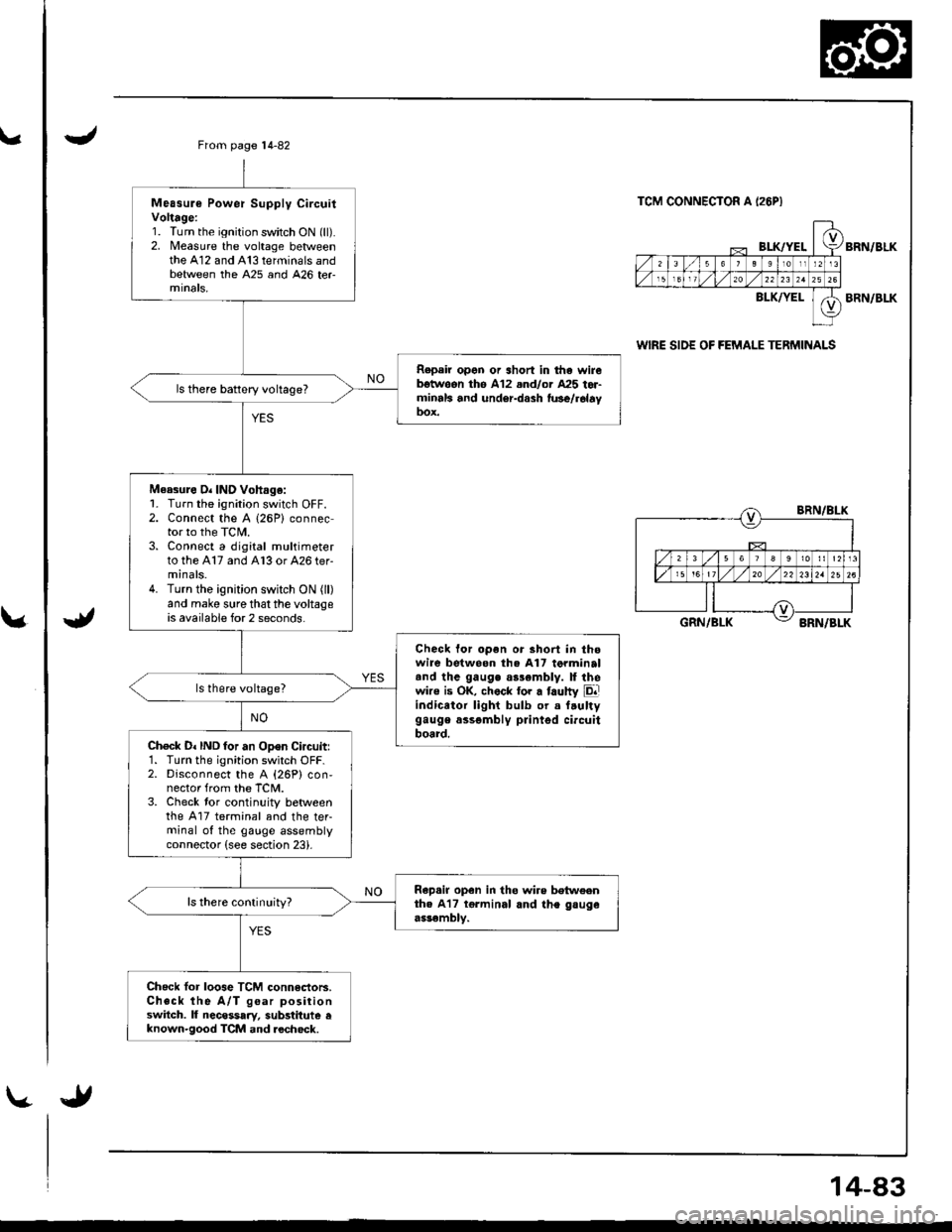
\.
\.
Measure Power Supply CircuitVoltage:1. Turn the ignition switch ON (ll).2. Measure the voltage betweenthe A12 and A13 terminals andbetween the A25 and 426 ter
Repeir open or short in tha wirebgtwoon th6 A12 .nd/or A25 tor-minrls and under-dash fu3e/r6layDox.
ls there battery voltage?
Measure O. IND Vohag.:1- Turn the ignition switch OFF.2. Connect the A (26P) connector to the TCIL3. Connect a digital multimeterto the A17 and A13 or 426 ter-minals.4. Turn the ignition switch ON (ll)
and make sure that the voltageis available for 2 seconds.
Check for open or short in thowire betweon the A17 torminaltnd the gauge as3emblv. ll thewire is OK, chock tor a faulty Eliindicator light bulb or a f.ultygauge assgmbly printgd circuitboard.Ch€ck D. IND for an Open Circuitr1. Turn the ignition switch OFF.2. Disconnect the A {26P} con,nector from the TCM.3. Check tor continuity betweenthe A17 terminal and the teFminal of the gauge assemblyconnector (see section 23).
Rap.ir open in tho wire betweenth. A17 tgrminal and the gsugeassembly.
ls there conlinuity?
Check lor loose TCM connectoB.Check the A/T goar positionswitch. lf necessary, substitute eknown-good TCM and.echock.
From page 14-82
TCM CONNECTOR A I26PI
BI-K/YELBRN/BLK
BLK/YELBRN/BLK
wlRE SIDE OF FEMALE TERMINALS
BRN/BLK
GRN/BLKBRN/BLK
14-83