HONDA INTEGRA 1998 4.G Workshop Manual
Manufacturer: HONDA, Model Year: 1998, Model line: INTEGRA, Model: HONDA INTEGRA 1998 4.GPages: 1681, PDF Size: 54.22 MB
Page 621 of 1681
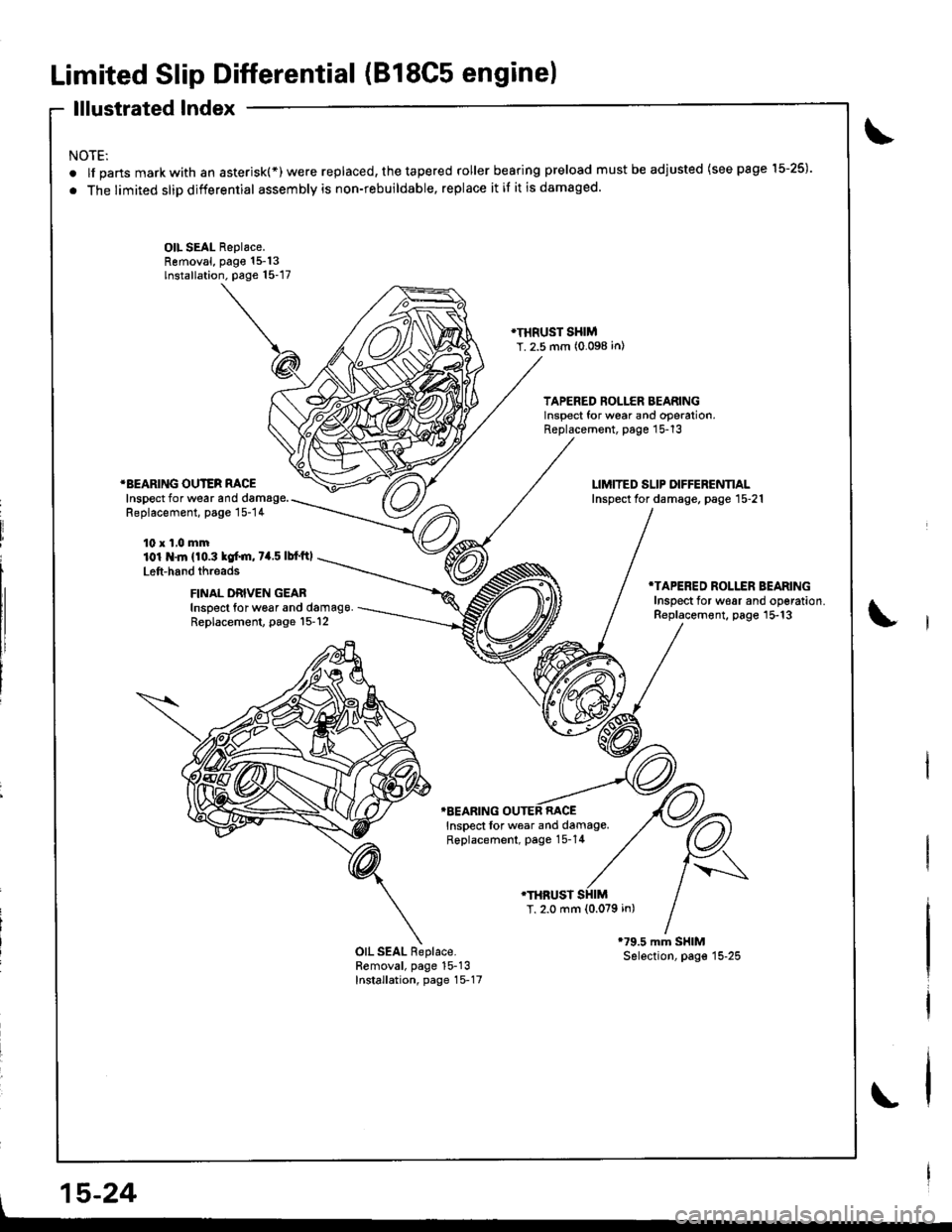
Limited Slip Differential (B18C5 engine)
lllustrated Index
NOTE:
.lfpartsmarkwithanasterisk(*)werereplaced,thetaperedrollerbearingpreloadmustbeadjusted(seepagel5-25).
. The limited slip differential assembly is non-rebuildable, replace it if it is damaged.
OIL SEAL Replace.Removal, page 15-13lnstallation. page 15-17
}I}IRUST SHIMT. 2.5 mm (0.098 in)
TAPERED ROLLER BEARINGlnsoect for wear and ooeration,Replacement, page 15-13
*BEARING OUTER RACEInspect for wear and damage.Replacement, page 15-14
10 x 1,0 mm101 .ln {10.3 kof.m, 7a.5 lbf'ftl
Left-hand threads
FINAL DRIVEN GEABInspect for w6ar and damag9.Replacement, page l5-12
*TAPERED ROLLER BEARINGInsDect for w€ar and oo€ration.Replacement, page 15-13
TBEARING OUTEB RACEInspect lor wear and damage.Replacement, page 15-14
.THRUST
T, 2.0 mm {0.079 in)
OIL SEAL Replace.Removal, page 15-13Installation, page 15-17
l,
, 15-24
Page 622 of 1681
J
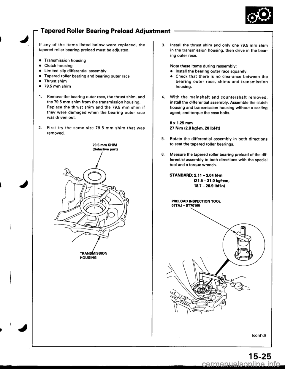
Tapered Roller Bearing Preload Adjustment
lf any of the items listed below were replaced, the
tapered roller bearing preload must be adjusted,
. Transmission housing
. Clutch housing
. Limited slip diffsrential assembly
. Tapored roller bearing and bearing outer race. Thrust shim
. 79,5 mm shim
Remove the bearing outer race, the thrust shim, and
the 79,5 mm shim from the transmission housing.
Replace the thrust shim and the 79.5 mm shim if
they were dsmaged when the bearing outer race
was driven out.
First try the same size 79.5 mm shim that was
removeo.
HOUSING
Install the thrust shim and only one 79.5 mm shim
in the transmission housing, then drive in the bear-
Ing our€r race.
Noto these items during rassembly:
. Install the bearing outer race squarely.. Check that there is no clearance between the
bearing outer race, shims and transmission
housing,
With the mainshatt and countershaft removed,
installthe differential assemblv. Assemble the clutch
housing and transmission housing without a sealing
a9ent, and torque the case bolts.
8 x 1.25 mm
27 N.m (2.8 kgf.m, 20 lM.ft)
Rotate the differential assemblv in both directions
to seat the tapered roller bearings.
Measur€ the tapered roller bearing preload of the dif-
ferential assembly in both directions with the special
tool and a toroue wrench.
STANDARD: 2.11 - 3.04 N.m(2!.5 - 31.0 kgt'cm,
18.7 - 26.9 lbf.in)
PNELOAD INSPECTION TOOL07TAJ - ST701dt
(cont'd)
15-25
Page 623 of 1681
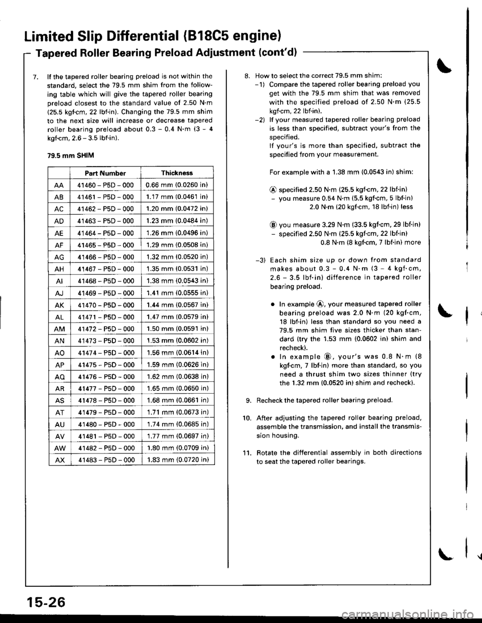
Limited Slip Differential (B18C5 engine)
Tapered Roller Bearing Preload Adiustment (cont'd)
7. lf the tapered roller bearing preload is not within the
standard, select the 79.5 mm shim from the follow-
ing table which will give the tapered roller bearing
preload closest to the standard value of 2.50 N'm
(25.5 kgicm, 22 lbf in). Changing the 79.5 mm shim
to the next size will increase or decrease tapered
roller bearing preload about 0.3 - 0.4 N'm (3 - 4
kgl.cm, 2.6 - 3.5 lbf.in).
79.5 mm SHIM
Part NumberThickness
41460-PsD-0000.66 mm (0.0260 in)
A841461 - P5D - 0001.17 mm (0.0461 in)
AC41462-P5D-0001.20 mm (0.0472 in)
AD41463-P5D-0001.23 mm (0.0484 in)
AE41464-P5D-0001.26 mm (0.0496 in)
AF41465-P5D-0001.29 mm (0.0508 in)
41466-PsD-0001.32 mm (0.0520 in)
AH41467-PsD-0001.35 mm (0.0531 in)
AI41468-P5D-0001.38 mm (0.0543 in)
AJ41469-PsD-0001.41 mm (0.0555 in)
AK41470-PsD-0001.44 mm (0.0567 in)
AL41471 - PsD - 0001.47 mm (0.0579 inl
41472-P5D-0001.50 mm (0.0591 in)
AN41473-P5D-0001.53 mm (0.0602 in)
AO41474-PsD-0001.56 mm (0.0614 in)
AP41475-P5D-0001.59 mm (0.0626 in)
AO41476-P5D-0001.62 mm (0.0638 in)
AR41477-P5D-0001.65 mm (0.0650 in)
AS41478-PsD-0001.68 mm (0.0661 in)
AT41479-P5D-0001.71 mm (0.0673 in)
AU41480-PsD-0001.74 mm (0.0685 in)
41481 - PsD - 0001.77 mm (0.0697 in)
41482-P5D-000'1.80 mm (0.0709 in)
AX41483-P5D-0001.83 mm (0.0720 in)
15-26
\
8. How to select the correct 79,5 mm shim:-1) Compare the tapered roller bearing preload you
get with the 79.5 mm shim that was removed
with the sDecified preload of 2.50 N'm (25.5
kgf.cm, 22 lbf.in).-2) lf vour measured tapered roller bearing preload
is less than specified, subtract your's from the
sDecified.
lf your's is more than specified, subtract the
specified from your measurement.
For example with a 1.38 mm (0.0543 in) shim:
@ specified 2.50 N.m (25.5 kgf.cm,22 lbiin)- you measure 0.54 N.m (5.5 kgf'cm, 5 lbf in)
2.0 N.m (20 kgf.cm, 18 lbf.in) less
@ you measure 3.29 N.m (33.5 kgf.cm, 29 lbf in)
- specified 2.50 N'm (25.5 kgf'cm, 22 lbf in)
0.8 N.m {8 kgf.cm. 7 lbf in) more
-3) Each shim size up or down from standard
makes about 0.3 - 0,4 N.m (3 - 4 kgf'cm,
2.6 - 3.5 lbf.in) difference in tapered roller
bearing preload.
o In example @, your measured tapered roller
bearing preload was 2.0 N.m (20 kgf.cm,
18 lbf.in) less than standard so you need a
79.5 mm shim five sizes thicker than stan-
dard (try the 1.53 mm (0.0602 in) shim and
recheck).
. In example @, your's was 0.8 N.m (8
kgf.cm,7 lbf.in) more than standard, so you
need a thrust shim two sizes thinner (try
the 1.32 mm {0.0520 in) shim and recheck).
Recheck the tapered roller bearing preload.
After adjusting the tapered roller bearing preload,
assemble the transmission, and install the transmis-
sion housing.
Rotate the difterential assembly in both directions
to seat the tapered roller bearings.
10.
11.
Page 624 of 1681
Differential (Automatic Transmission)
Speciaf Tools ........... ..........15-2A
Differential (Automatic Transmissionl
lllustrated Index .......... .. 15-29
Backlash Inspection ...... 15-30
Bearing Rep|acement ......................... I 5-30
Differential Carrier Replacement ...... l5-31
Oil SealRemoval ........... 15-32
Oil Seal Installation/
Side G|earance ................................. 1 5-32
Page 625 of 1681
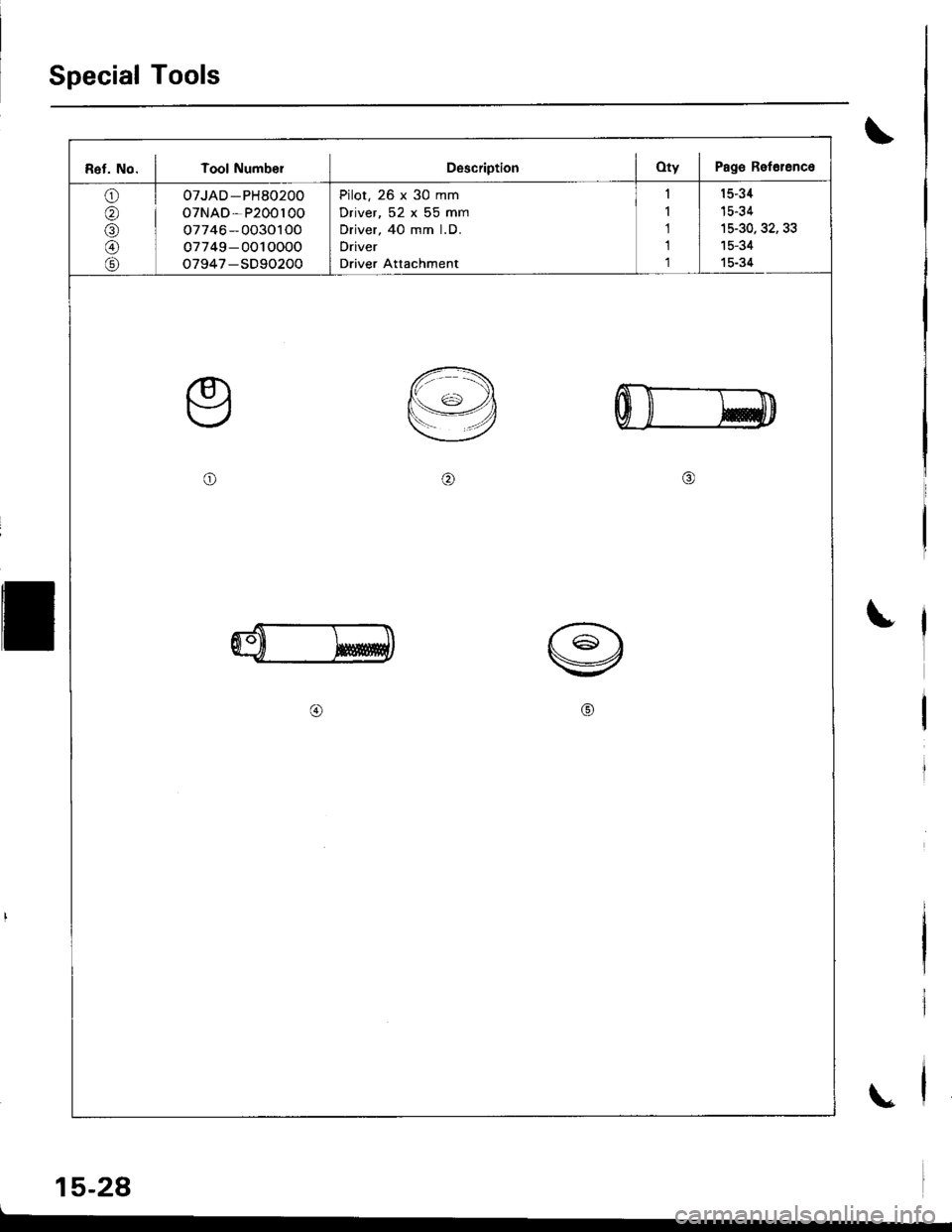
Special Tools
\
\
15-28
Ref. No. I Tool NumbelDescriptionOty I Pag6 Retolence
o
@
\9/
oTJAD-PH80200
oTNAD-P200100
o7746-0030100
o7749-0010000
o7947-SD90200
Pilot. 26 x 30 mm
Driver, 52 x 55 mm
Driver, 40 mm l.D.
Driver
Driver Attachment
1
I
1
1'l
r5-34
15-34
15-30, 32, 33
15-34
15-34
o@
@!b_./
\
Page 626 of 1681
Differential (Automatic Transmission)
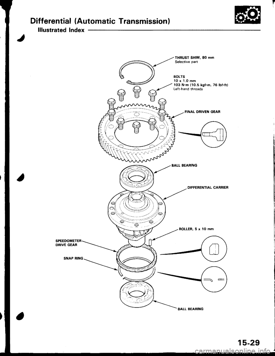
lllustrated Index
FINAL DRIVEI{ GEAR
BALL BEARIiIG
--tot"'
ENTIAL caRRlER
ROLLER,5xlOmm
BALL BEARING
15-29
Page 627 of 1681
Differential (Automatic Transmissionl
Backlash Inspection
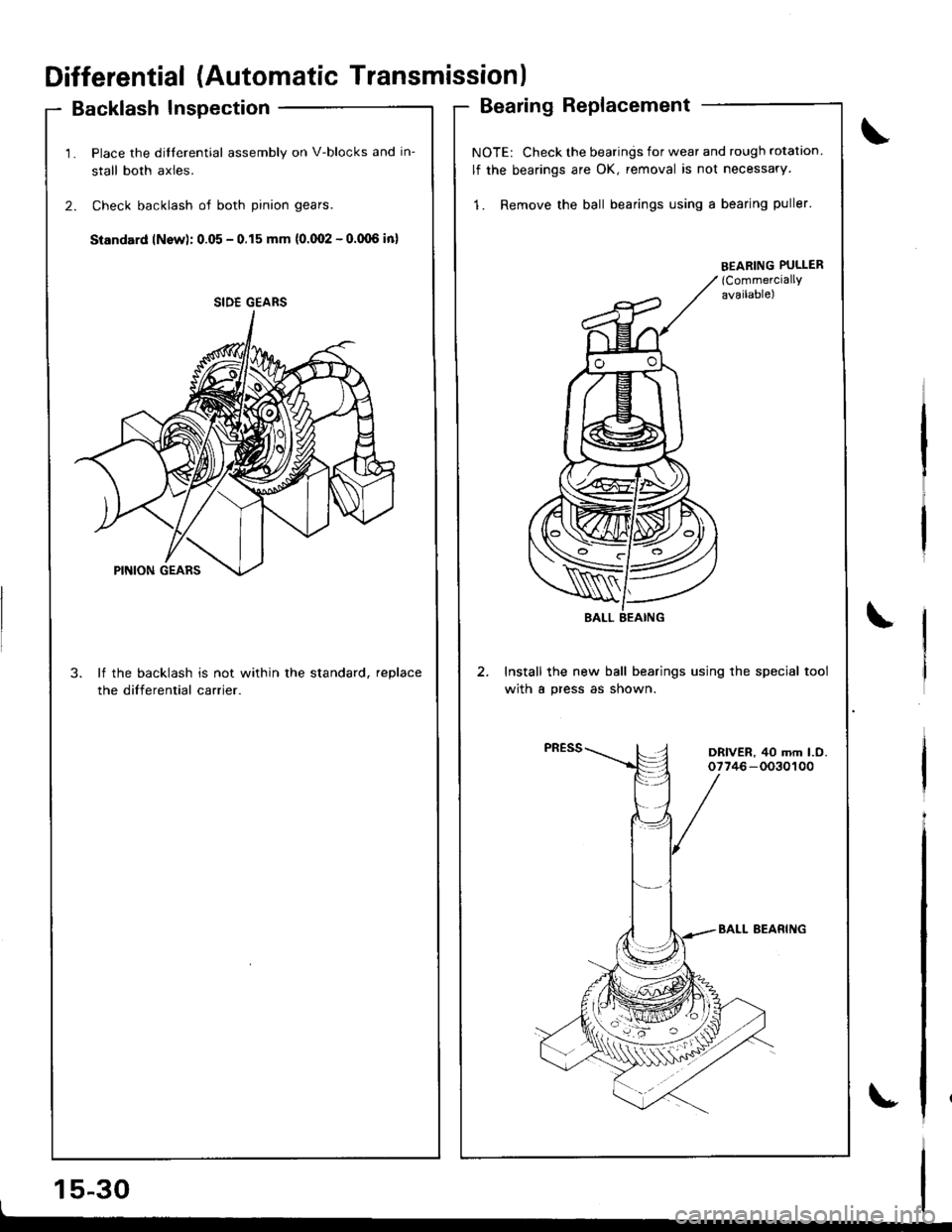
1. Place the dilferential assembly on V-blocks and in-
stall both axles.
2. Check backlash of both pinion gears.
Standard lNsw): 0.05 - 0.15 mm {0.(Xt2 - o.(Xl6 in)
3. lf the backlash is not within the standard, reDlace
the differential carrier.
15-30I
Bearing Replacement
NOTE: Check the bearings for wear and rough rotation
lf the bearings are OK, removal is not necessary.
1. Remove the ball bearings using a bearing puller'
Install the new ball bearings using the special tool
with a press as shown.
SIDE GEARS
EEABING PULLER(CommerciallY
available)
\
DRIVER, 40 mm l.O.07746-0030100
Page 628 of 1681
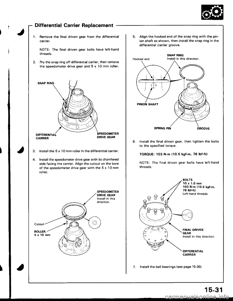
J1. Remove the final driven gear from the differential
carner.
NOTE: The final driven gear bolts have left-hand
threads.
2. Pry the snap ring ofl differential carrier, then remove
the speedometer d.ive gear and 5 x 1O mm roller.
SNAP RING
DIFFERENTIALCARRIERDRIVE GEAR
lnstall the 5 x 1O mm roller in the differential carrier.
Installthe speedometer drive gear with its chamfered
side facing the carrier. Align the cutout on the bore
of the speedometer drive gear with the 5 x 1O mm
ro er.
SPEEDOMETERDRIVE GEARInstall in thisdirection.
Cutout
ROLLER,5x10mm
5. Align the hooked end ot the snap ring with the pin-
ion shaft as shown. then install the snap ring in the
dilJerential carrier groove.
Hooked endSNAP RINGInstall in this direction.
6.Install the final driven gear, then tighten the bolts
to the specified torque.
TOROUE: 103 N.m (10.5 kgt.m, 76 lbl.ttl
NOTE: The final driven gear bolts have left-hand
threads.
BOLTS10 x 1.0 mm103 N.m (10.5 kgf.m,76 rbt.frlLeft-hand threads
FINAL DRIVENGEARInstall in this direction.
DIFFERENTIALCARRIER
7. Installthe ball bearings (see page 15-30).
Page 629 of 1681
Differential (Automatic Transmissionl
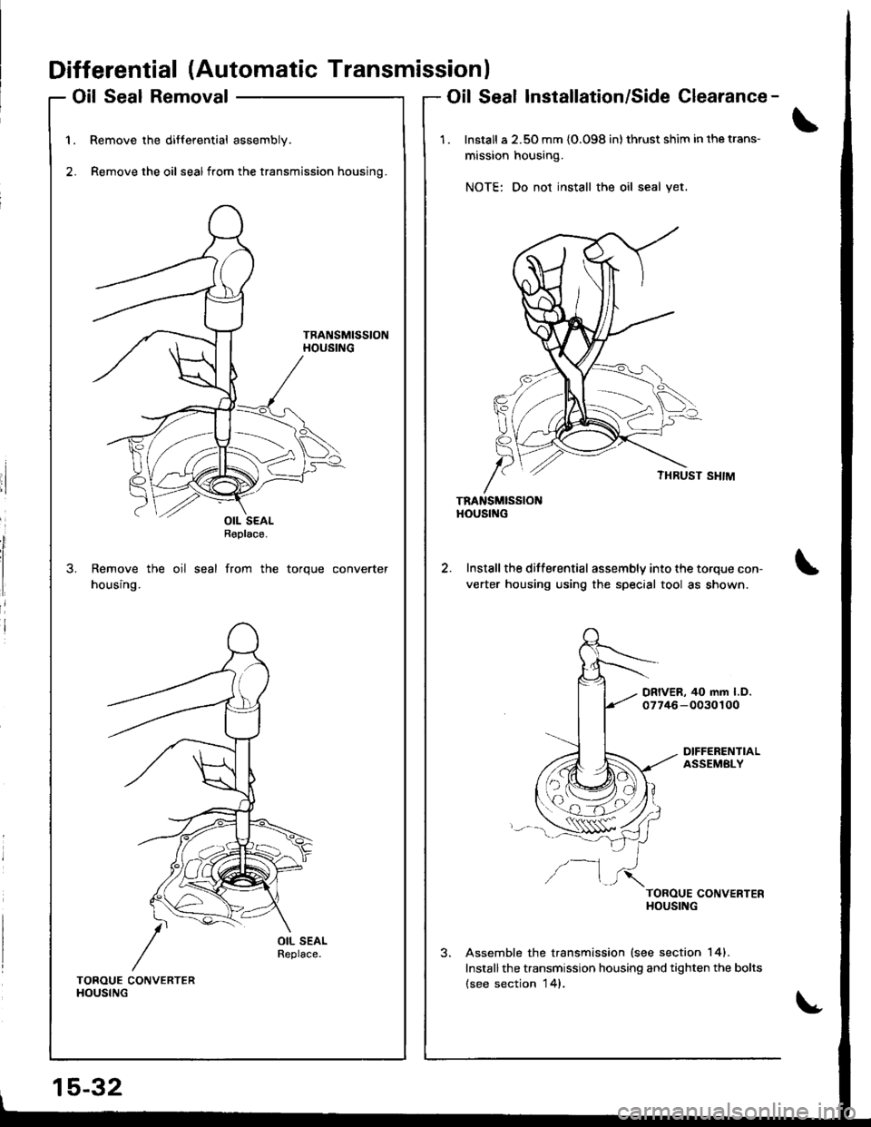
Oil Seal Removal
Remove the differential assembly.
Remove the oil sealfrom the transmission housing.
Remove the oil seal from the torque converter
housing.
Oil Seal Installation/Side Clearance-
1 . Install a 2.50 mm {O.O98 in} thrust shim in the trans-
mission housing.
NOTE: Do not install the oil seal yet.
TRANSMISSIONHOUStf{G
Install the differential assembly into the torque con-
verter housing using the special tool as shown.
DRIVER, 40 mm l.D.07746-0030100
DIFFERENTIALASSEMBLY
/--1TOROUE CONVERTERHOUSING
Assemble the transmission lsee section 141.
Installthe transmission housing and tighten the bolts(see section 14).TOROUE CONVERTERHOUSING
15-32
OIL SEALReplace.
Page 630 of 1681
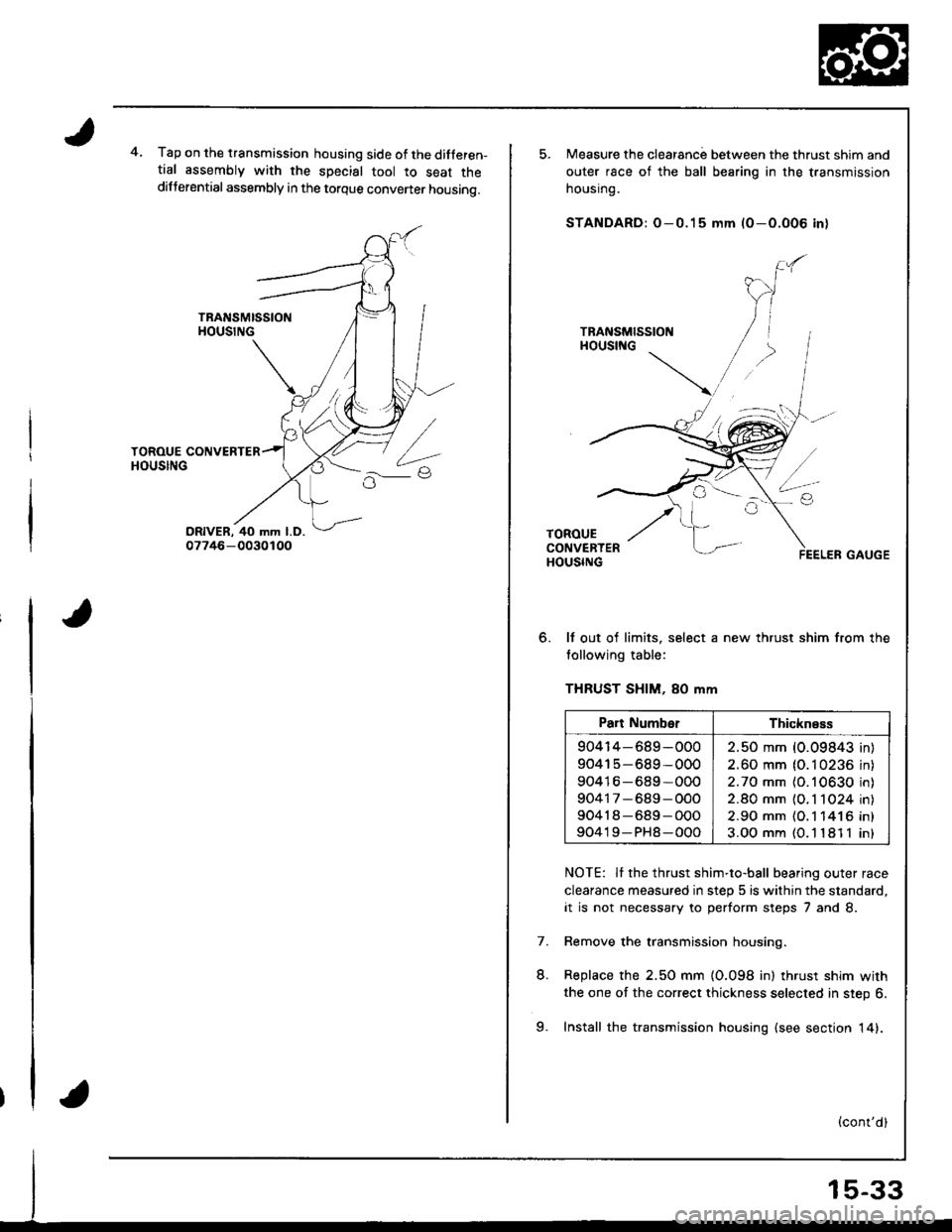
4.Tap on the transmission housing side of the ditferen-tial assembly with the special tool to seat thedifferential assembly in the torque convener housing.
o.
Measure the clearanc; between the thrust shim and
outer race of the ball bearing in the transmission
nousrng.
STANDARD: O-0.15 mm (O-O.O06 in)
It out of limits. select a new thrust shim from the
tollowing table:
THRUST SHIM, 80 mm
NOTE: Il the thrust shim-to-ball bearing outer race
clearance measured in step 5 is within the standard,
it is not necessary to perform steps 7 and 8.
Remove the transmission housing.
Replace the 2.50 mm {0.098 in) thrust shim with
the one of the correct thickness selected in step 6.
Install the transmission housing (see sectjon 14).
7.
L
Part NumberThickness
904r4-689-000
90415-689-000
90416-689*000
90417-689-OOO
90418-689-O00
90419-PH8-000
2.50 mm (0.09843 in
2.60 mm (0.10236 in
2.70 mm (O.10630 in
2.80 mm {O. 1 1O24 in
2.90 mm {O.1 141 6 in
3.OO mm (O. l '181 1 in
9.