HONDA INTEGRA 1998 4.G Workshop Manual
Manufacturer: HONDA, Model Year: 1998, Model line: INTEGRA, Model: HONDA INTEGRA 1998 4.GPages: 1681, PDF Size: 54.22 MB
Page 651 of 1681
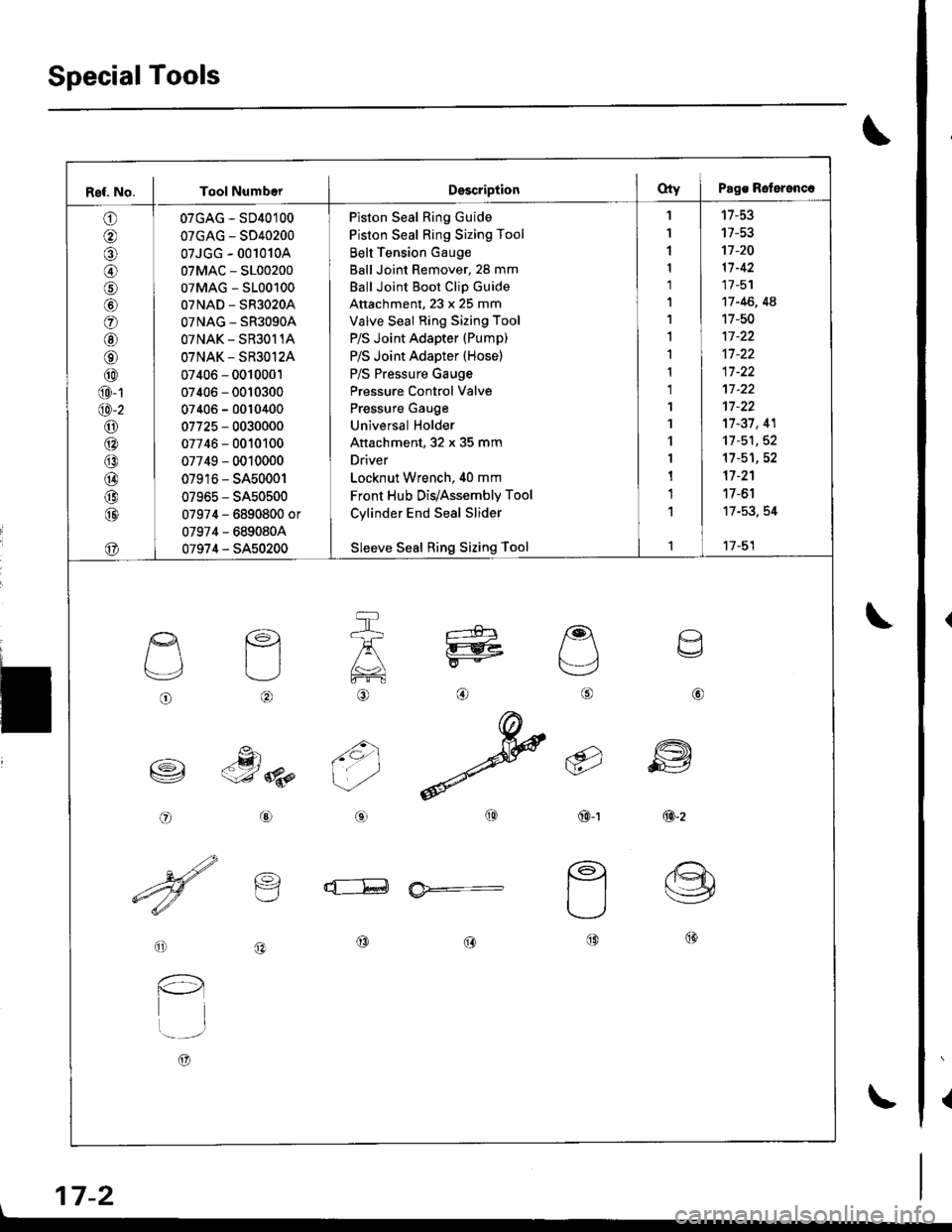
SpecialTools
{
\
\
17-2
Ref. No. I Tool NumberDsscriptionOty I Pags Reterenc.
o
@
@
o
@
@
@
@
@
@-1
@-2
o6:^
@
@
@
@
@
07GAG - SD40100
07GAG - SD40200
07JGG - 001010A
07MAC - S100200
07MAG - S100100
07NAD - SR3020A
OTNAG _ SR3OgOA
OTNAK - SR3O11A
OTNAK - SR3O12A
07406 - 0010001
07406 - 0010300
07406 - 0010400
07725 - 0030000
07746 - 0010100
07749 - 0010000
07916 - SA50001
07965 - SA50500
07974 - 6890800 or
07974 - 6890804
07974 - SA50200
Piston Seal Ring Guide
Piston Seal Ring Sizing Tool
Belt Tension Gauge
Ball Joint Remover, 28 mm
Ball Joint Boot Clip Guide
Attachment, 23 x 25 mm
Valve Seal Ring Sizing Tool
P/S Joint Adapter (Pump)
P/S Joint Adapter (Hose)
P/S Pressure Gauge
Pressure Control Valve
Pressure Gauge
Universal Holder
Attachment, 32 x 35 mm
Driver
Locknut Wrench. 40 mm
Front Hub Dis/Assembly Tool
Cylinder End Seal Slider
Sleeve Seal Ring Sizing Tool
'I
1
1
1
1'|
1,l
I
1
1
1'I
'l
1
1
1
1
1
't7-53
17-53't]-20
11-42
17 -51
17 -46, 4A
17-50
17-37, 41
11-51,52't1-51,52
17 -2'�1
17 -6'l
17-53. 54
17-51
o
L'4,
o
€)
-g)c-J 8p
@
@
6i
(9')\E/'
@-t
a
6
ffi
@-z
d--E ia*=-
o
l-l
t..-_-.r
A)
@@@
\
Page 652 of 1681
I
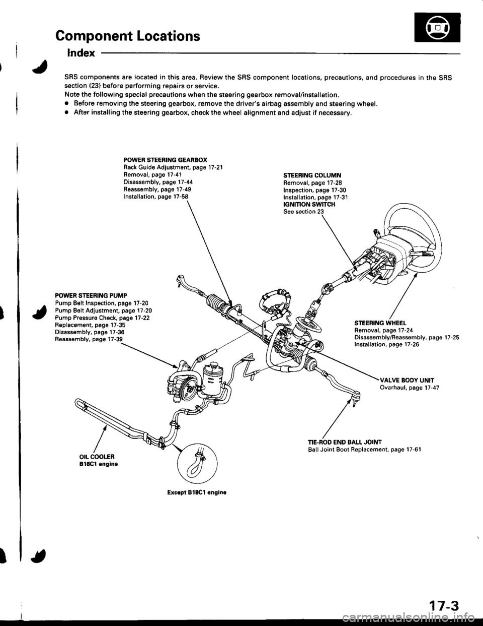
Component Locations
Index
SRS components are located in this area. Review the SRS component locations, precautions, and procedures in the SRSsection (23) before performing repairs or service.
Note the following special precautions when the steering gearbox removal/installation,
. Before removing the steering gearbox, remove the driver's airbag assembly and steering wheel.
. After installing the steering gearbox, ch6ck the wheel alignmentand adjust if necessary.
POWER STEERING GEARBOXRack Guid€ Adjustment, page 17 -21
Removal, pago 17-4'1Disassembly, page 17-44Reassombly. page'17-49Installation, page 17-58
STEEBING COLUMNRemoval. page 17-28Inspection, pago 17-30Installation, page 17-3'1|GNMON SWITCHSee section 23
POWER STEERING PUMPPump Belt Inspection. page 17-20Pump Belt Adjustment, page 17 -20
Pump Pr€ssuro Check, page 17'22Roplacament, page 17-35Dis686embly, page 17-36Reassembly, page 17-39
STEEBING WHEELRomoval, page 17-24Disassembf y/Reassembly, paga 17 -25
Installation, page 17-26
TIE.BOD END BALL JOINTBallJoint Boot Replacement, page 17-61
Exc.pt BlSCl onginc
17-3
Page 653 of 1681
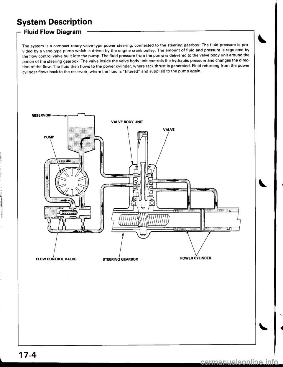
System Description
Fluid Flow Diagram
The system is a compact rotary-valve-type power steering, connected to the steering gearbox. The fluid pressure is pro-
vided by a vane-type pump which is driven by the engine crank pulley. The amount of fluid and pressure is regulated by
the flow control valve built into the pump. The fluid pressure from the pump is delivered to the valve body unit around the
pinion of the steering gearbox. The valve inside the valve body unit controls the hydraulic pressure and changes the direc-
tion of the tlow. The fluid then flows to the power cylinder, where rack thrust is generated. Fluid returning from the power
cylinder flows back to the reservoir, where the fluid is "filtered" and supplied to the pump again
li
I
VALVE BODY UNIT
GEARBOXFLOW CONTROL VALVEPOWER CYLINDER
17-4
Page 654 of 1681
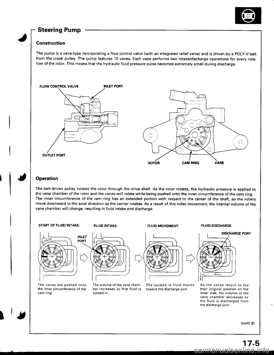
Steering Pump
Construc'tion
The pump is a vane-type incorporating a flow control valve (with an integrated relief valve) and is driven by a POLY-V-belt
from the crank pulley. The pump features 10 vanes. Each vane performs two intake/discharge operations for every rota-tion of the rotor. This means that the hydraulic fluid pressure pulse becomes extremely small during discharge.
Operation
The belt-driven pulley rotates the rotor through the drive shaft. As the rotor rotates. the hydraulic pressure is applied tothe vane chamber of the rotor and the vanes will rotate while being pushed onto the inner circumference of the cam ring.The inner circumference of the cam ring has an extended portion with respect to the center of the shaft, so the rollersmove downward in the axial direction as the carrier rotates. As a result of this roller movement, the internal volume of thevane chamber will change. resulting in fluid intake and discharge.
START OF FLUID INTAK€:FLUID INTAKE:FLUIO MOVEMENT:FLUID DISCHARGE:
DISCHARGE PORT
The vanes are pushed onlothe inner circumference of thecam ring.
The volume of the vane cham-ber increases so that fluid issucked in.
The sucked in fluid movestoward the discharge port.As the vanes return to thetheir original position on theinner side, the volume of thevane chamber decreases sothe fluid is discharged fromthe discharge port-
I(cont'd)
OUTLET PORT
17-5
Page 655 of 1681
System Description
Steering Pump (cont'd) .
17-6
Flow Control
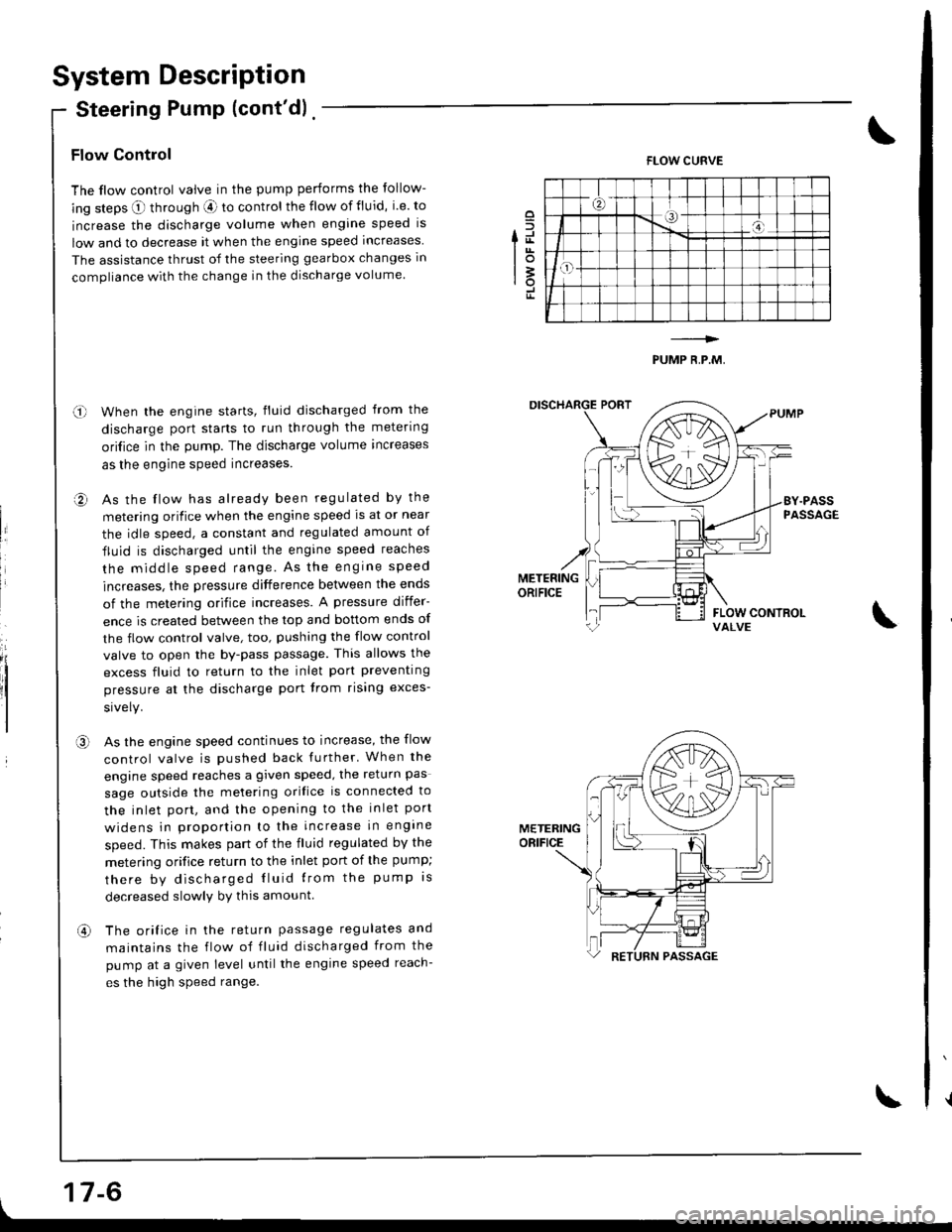
The flow control valve in the pump performs the follow-
ing steps O through aE ro control the flow of fluid, i.e. to
increase the discharge volume when engine speed is
low and to decrease it when the engine speed increases
The assistance thrust of the steering gearbox changes in
compliance with the change in the discharge volume.
When the engine starts, fluid discharged from the
discharge port starts to run through the metering
ori{ice in the pump. The discharge volume increases
as the engine speed increases.
As the flow has already been regulated by the
metering orifice when the engine speed ls at or near
the idle speed, a constant and regulated amount of
fluid is discharged until the engine speed reaches
the middle speed range. As the engrne speed
increases, the pressure difference between the ends
of the metering orifice increases. A pressure differ-
ence is created between the top and bottom ends of
the flow control valve, too, pushing the flow control
valve to open the by-pass passage. This allows the
excess fluid to return to the inlet port preventing
pressure at the discharge port trom rising exces-
As the engine speed continues to increase, the flow
control valve is pushed back further' When the
engine speed reaches a given speed, the return pas
sage outside the melering orifice is connected to
the inlet port, and the opening to the inlet port
widens in prooortion to the increase in engine
speed. This makes part of the fluid regulated by the
metering orifice return to the inlet port of the pump;
there by discharged Iluid lrom the pump rs
decreased slowlv by this amount
The orifice in the return passage regulates and
maintains the flow of fluid discharged from the
pump at a given level untilthe engine speed reach-
es the high speed range.
o
fd
lot3rotr
FLOW CURVE
PUMP R,P.M,
o-l
a,
II
,a\
METERINGORIFICE
an
Page 656 of 1681
Pressure Relief
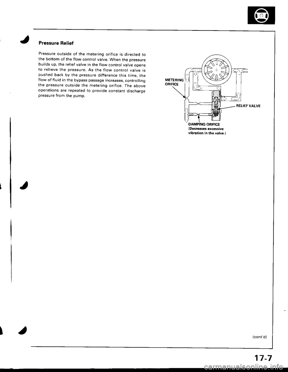
Pressure outside of the metering orifice is directed tothe bonom of the flow control valve. When the pressure
builds up, the relief valve in the flow control valve opensto relieve the pressure. As the flow control valve ispushed back by the pressure difference this time. theflow of fluid in the bypass passage increases, controllingthe pressure outside the metering orifice. The aboveoperatrons are repeated to provide constant discharaepressure from the pump.
I
(Decresses excossivevibration in the valve.)
VALVE
(cont'd)
17-7
Page 657 of 1681
System DescriPtion
Steering Gearbox
it
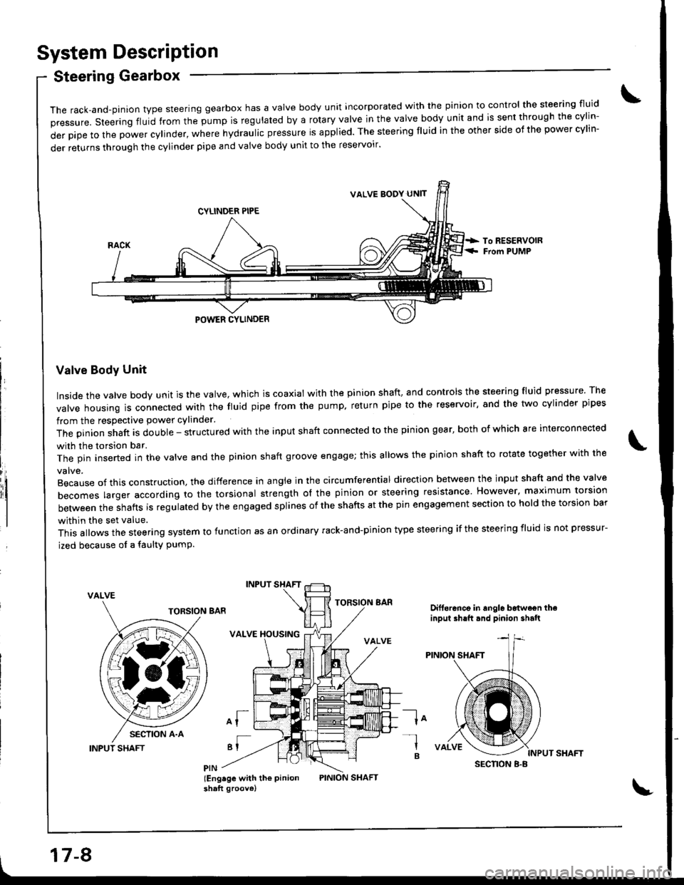
The rack,and-pinion type steering gearbox has a Valve body unit incorporated with the pinion to control the steering fluid
pressure. steering fluid from the pump is regulated by a rotary valve in the valve body unit and is sent through the cylin-
derpipetothepowercy|inder,wherehydrauIicpressureisapp|ied.Thesteeringf|Uidintheothersideofthepowercy|in-
der returns through the cylinder pipe and valve body unit to the reservoir'
Valve Body Unit
Inside the valve body unit is the valve, which is coaxial with the pinion shaft, and controls the steering fluid pressure The
valve housing ls connected wirh the fluid pipe from the pump. return pipe to the reservoir, and the two cylinder pipes
from the respective power cylinder.
The pinion shaft is double - structured with the input shaft connected to the pinion gear, both of which are interconnected
with the torsion bar.
The pin inserted in the valve and the pinion shaft groove engage; this allows the pinion shaft to rotate together with the
Because of this construction. the difference in angle in the circumferential direction between the input shaft and the valve
becomes larger according ro the torsional strength ol the pinion or steering resistance. However. maximum torsion
between the shafts is regulated by the engaged splines of the shafts at the pin engagement section to hold the torsion bar
within the set value.
This allows the steering system to function as an ordinary rack-and-pinion type steering if the steering iluid is not pressur-
ized because of a faulty PumP.
VALVE
INPUT SHAFT
INPUT SHAFT
VALVE XOUSING
of
'I
lEng.ge with th€ Pinionshaft groove)
TORSION BARDift6rance in angle b6twe€n theinput ih.ft.nd pinion shalt
la-l
B
VALVE BODY UN]T
SECNON B.B
17-8
Page 658 of 1681
INPUT SHAFT
High assist at lower speedsl
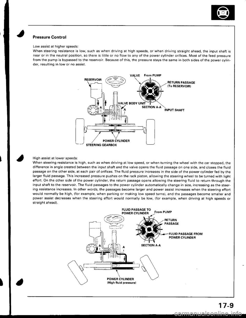
When steering resistance is high, such as when driving at low speed, or when turning the wheel with the car stopped, the
diiference in angle created between the input shaft and the valve opens the tluid passage on one side, and closes the fluidpassage on the other side, at each pair of orifices. The fluid pressure lncreases in the side of the power cylinder fed by thelarger fluid passage. This increased pressure pushes on the rack piston, allowing the steering wheel to be turned with light
effon. On the other side of the power cylinder, the return passage opens allowing the steering fluid to return through theinput shaft to the reservoir. The fluid passages to the power cylinder automatically change in size, increasing as the steer-ing resistance increases. In other words, the passages become larger and power assist increases when the steering effort
would normally be high, (for example, when parking or making low speed turns), and the passages become smaller andpower assist decreases when the steering effort would normally be low, (for example, when driving at high speeds or
straight ahead).
FLUIO PASSAGE TOPOWER CYLINDER
Ce) r.r;
VK
Pressure Control
Low assist at higher speedsl
When steering resistance is low, such as when driving at high speeds, or when driving straight ahead. the lnput shaft is
near or in the neutral position, so there is liftle or no flow to any of the power cylinder orifices. Most of the feed pressure
from the pump is bypassed to the reservoir. Because of this, the pressure stays the same in both sides of the power cvlin-
der, resulting in low or no assist.
RETURN PASSAGE{To RESERVOIR)
POWER CYLINDERlHigh fluid pressurelI
ALVE FTom PUMP
RESERVOIR
SECTION A-A
17-9
Page 659 of 1681
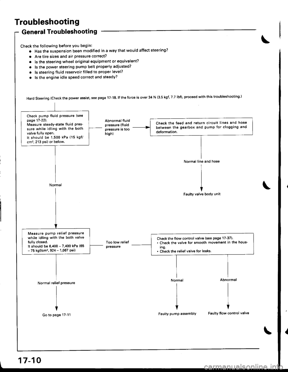
Troubleshooting
General Troubleshooting
Check the following before you begin:
o Has the suspension been modified in a way that would affect steering?
. Are tire sizes and air pressure correct?
. lsthe steering wheel original equipment or equivalent?
. ls the power steering pump belt properly adiusted?
. ls steering fluid reservoirtilled to proper level?
. ls the engine idle speed correct and steadyT
Hard steering (check the power assist, see page 17-18. It the torce is over 34 N (3.5 kgf, 7 7 lbf), proceed with this troubl*hooting l
Abnormalfluidpressur€ (lluid
pressure rs roohish)
Too low reliefpress{ire
Normal line and hos6
I
II
iFaulty valve body unit
Normal Abnormal
rlrl
l{
Faulty pump assembly Faulty tlow control valv6
Ch€ck the tegd and return circuit lines and hoso
between the gearbox and pump for clogging and
detormation.
Check pump fluid Pressuro {sespage 17'221.Mgasure stoady-stat€ fluid Pres_sure while idling with the both
valv6Iully opon.It should be 1,500 kPa (15 kgf/
cm,,213 psi) or below.
Normal
Check the flow control valve (seo page 17-37).. Check the valvs Ior smooth movemont in the hous-
Ing.. Check tho reliel valvo for leaks.
Measure pump reliet prgssure
while idling with the both vslveIully closed.It should b€ 6,400 - 7,400 kPa {65- 75 kgt/cm'�, 924 - 1,067 psi)
Normal reliel pressure
I
I
+
Go to pags 17-11
17-10
Page 660 of 1681
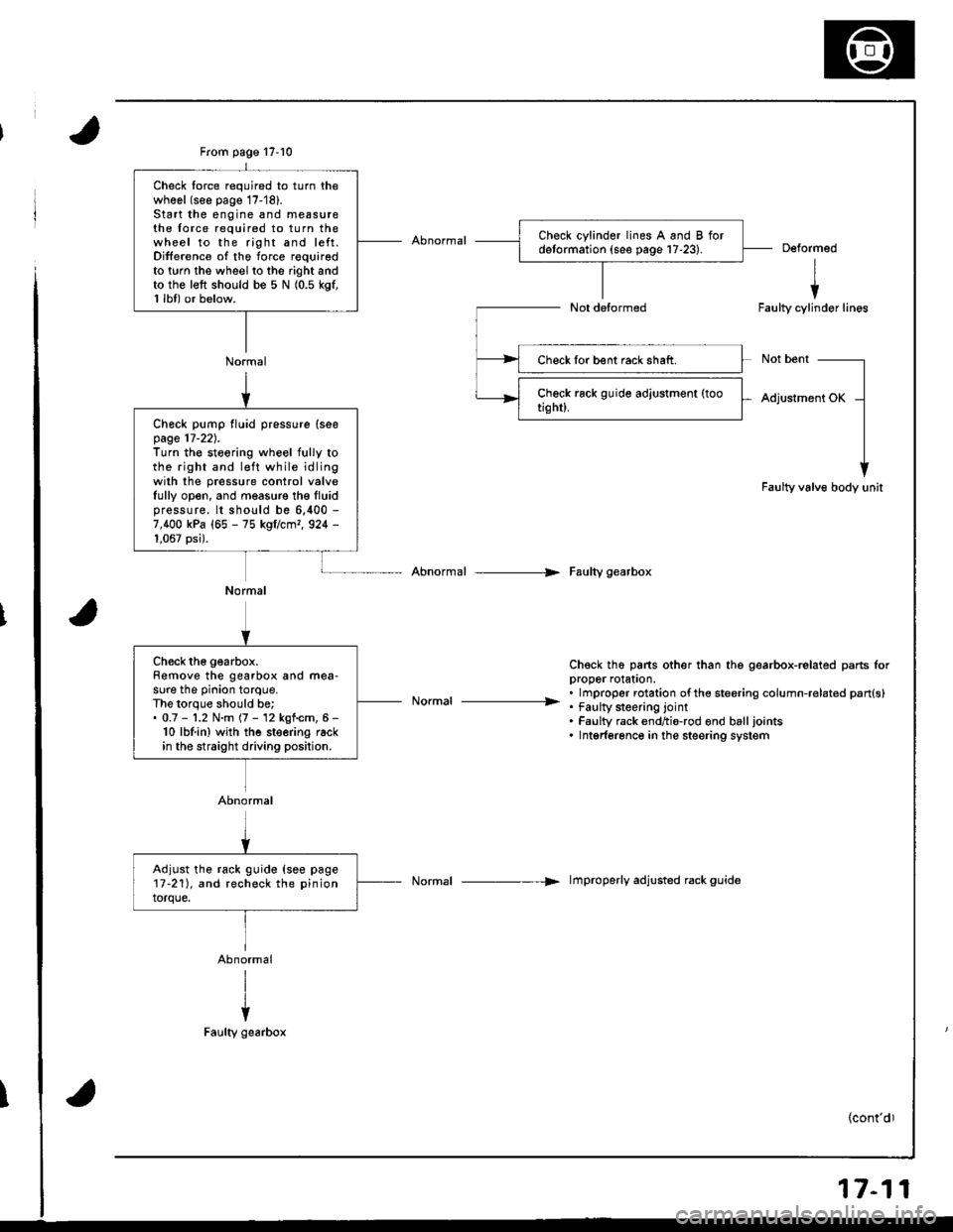
From page 17-10
Normal
Check lorce required to turn thewhool (see page 17-'18).Start the engine and measu16the force required to turn thewheel to the right and left.Difference of the force requiredto twn the wheel to the right andto the left should be 5 N (0.5 kgf,1 lbl) or below.
Deformed
I
iFaulty cylinder lines
Not bent
Adjustment OK
Faulty valve body unit
Abnormal --> Faulty gearbox
Ch€ck th6 pans other than the gearbox-related parts lorDrooer rolaton.
. . lmproper rotation ofthe steering column-related pan{s}----------------- . tau[y $eenng lornt. Faulty rack endtio-rod ond balljoints. Intgrferonce in the steering system
Normal -----> lmproperly adjusted rack guide
Check lor bent rack shaft.
Check pump fluid pressure (seepage 17-22).Turn the steoring wheel fully tothe right and l€ft while idlingwilh the pressure control valveIully open, and measure the Iluidpressure. lt should be 6,400 -
7,400 kPa (65 - 75 kgflcmr, 924 -
1,067 psi).
Normal
Ch€ck the gearbox.Remove the gearbox and mea-sure the pinion torque.The lorque should be;. 0.7 - '1.2 N.m (7 - 12 kgf.cm, 6 -
10 lbf.in) wjth the steering rackin the straight driving position.
Abnormal
Adjust the rack guide {see page17-211, and recheck the pinion
torque.
17-11