INFINITI FX35 2008 Service Manual
Manufacturer: INFINITI, Model Year: 2008, Model line: FX35, Model: INFINITI FX35 2008Pages: 3924, PDF Size: 81.37 MB
Page 3731 of 3924

SE-92
< SERVICE INFORMATION >
FRONT SEAT
Be sure to insert the rear end tab of the rear leg cover under the rail.
REMOVAL OF SEATBACK TRIM AND PAD
1. Remove the seatback garnish.
2. Remove the retainer.
3. Remove the stay securing the inner cloth.
4. Remove the headrest.
5. Remove the headrest holder.From the back of the seatback, press the headrest holder tab of
the stay pipe hole to disengage. Then pull the headrest holder
up to remove.
NOTE:
Before installing the headrest holder , check its orientation (front,
rear, left and right).
PIIA6041E
PIIA6042E
PIIA6048E
PIIA6050E
3AA93ABC3ACD3AC03ACA3AC03AC63AC53A913A773A893A873A873A8E3A773A983AC73AC93AC03AC3
3A893A873A873A8F3A773A9D3AAF3A8A3A8C3A863A9D3AAF3A8B3A8C
Page 3732 of 3924

FRONT SEATSE-93
< SERVICE INFORMATION >
C
DE
F
G H
J
K L
M A
B
SE
N
O P
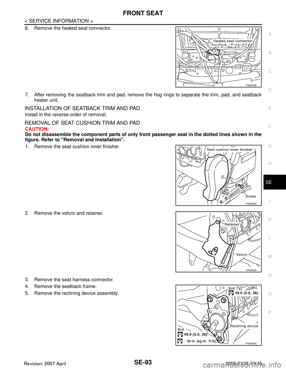
6. Remove the heated seat connector.
7. After removing the seatback trim and pad, remove t he hog rings to separate the trim, pad, and seatback
heater unit.
INSTALLATION OF SEATBACK TRIM AND PAD
Install in the reverse order of removal.
REMOVAL OF SEAT CUSHION TRIM AND PAD
CAUTION:
Do not disassemble the component parts of only fron t passenger seat in the dotted lines shown in the
figure. Refer to "Removal and Installation".
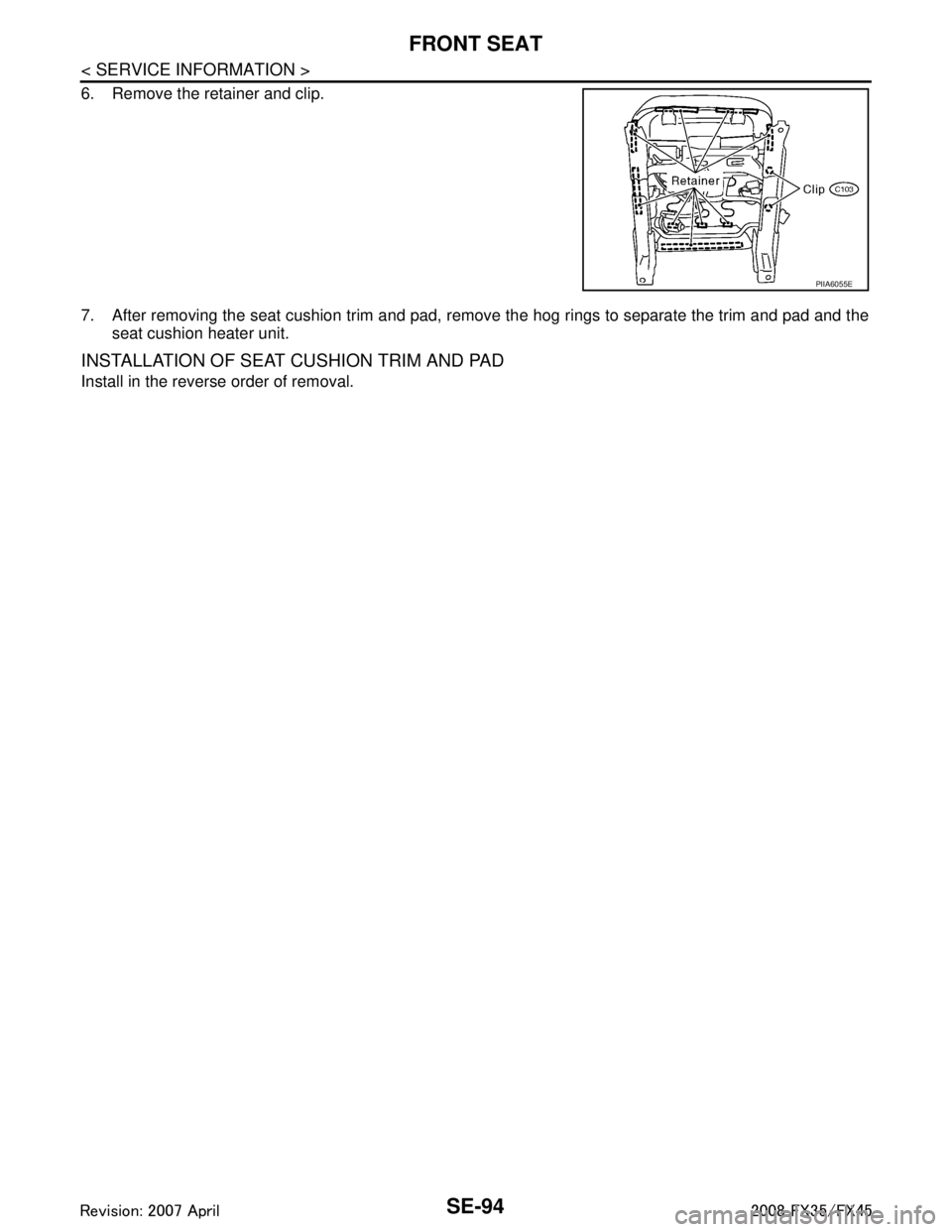
1. Remove the seat cushion inner finisher.
2. Remove the velcro and retainer.
3. Remove the seat harness connector.
4. Remove the seatback frame.
5. Remove the reclining device assembly.
PIIA6049E
PIIA6052E
PIIA6053E
PIIA6054E
3AA93ABC3ACD3AC03ACA3AC03AC63AC53A913A773A893A873A873A8E3A773A983AC73AC93AC03AC3
3A893A873A873A8F3A773A9D3AAF3A8A3A8C3A863A9D3AAF3A8B3A8C
Page 3733 of 3924

SE-94
< SERVICE INFORMATION >
FRONT SEAT
6. Remove the retainer and clip.
7. After removing the seat cushion trim and pad, remove the hog rings to separate the trim and pad and theseat cushion heater unit.
INSTALLATION OF SEAT CUSHION TRIM AND PAD
Install in the reverse order of removal.
PIIA6055E
3AA93ABC3ACD3AC03ACA3AC03AC63AC53A913A773A893A873A873A8E3A773A983AC73AC93AC03AC3
3A893A873A873A8F3A773A9D3AAF3A8A3A8C3A863A9D3AAF3A8B3A8C
Page 3734 of 3924

REAR SEATSE-95
< SERVICE INFORMATION >
C
DE
F
G H
J
K L
M A
B
SE
N
O P
REAR SEAT
Removal and InstallationINFOID:0000000001328149
PIIB8527E
1. Headrest (side) 2. Headrest holder (free) 3. Headrest holder (locked)
4. Seatback trim (RH) 5. Seatback pad (RH) 6. Seatback frame (RH)
7. Nut 8. Seat hinge cover (RH) 9. Screw
10. Reclining lever (RH) 11. Reclining device outer cover (RH) 12. Reclining device inner cover (RH)
3AA93ABC3ACD3AC03ACA3AC03AC63AC53A913A773A893A873A873A8E3A773A983AC73AC93AC03AC3
3A893A873A873A8F3A773A9D3AAF3A8A3A8C3A863A9D3AAF3A8B3A8C
Page 3735 of 3924

SE-96
< SERVICE INFORMATION >
REAR SEAT
REMOVAL
1. Pull the lock at the front bottom of the seat cushion forward (1
for each side), and pull the seat cushion upward to release the
wire from the plastic hook, then pull the seat cushion forward to
remove.
2. Remove the seatback mounting nuts.
3. Remove the seatback mounting bolt and nut. Remove the remote control wire.
INSTALLATION
Install in the reverse order of removal.
NOTE:
After rear wheel house finisher assembly is remove the seatback is installed. Refer to EI-45, "
Component
Parts Location".
REMOVAL OF SEAT CUSHION TRIM AND PAD
13. Bolt 14. Seatback garnish (RH) 15. Trunk net hook
16. Clip (C101) 17. Headrest (center) 18. Seatback trim (LH)
19. Seatback pad (LH) 20. Seatback frame (LH) 21. Seatback garnish (LH)
22. Armrest bracket cover 23. Armrest bracket 24. Armrest
25. Reclining device inner cover (LH) 26. Reclining device outer cover (LH) 27. Reclining lever (LH)
28. Seat hinge cover (LH) 29. Seat cushion trim 30. Seat cushion pad
31. Cup holder bracket 32. Cup holder
PIIA6034E
PIIA6035E
PIIA6036E
3AA93ABC3ACD3AC03ACA3AC03AC63AC53A913A773A893A873A873A8E3A773A983AC73AC93AC03AC3
3A893A873A873A8F3A773A9D3AAF3A8A3A8C3A863A9D3AAF3A8B3A8C
Page 3736 of 3924

REAR SEATSE-97
< SERVICE INFORMATION >
C
DE
F
G H
J
K L
M A
B
SE
N
O P
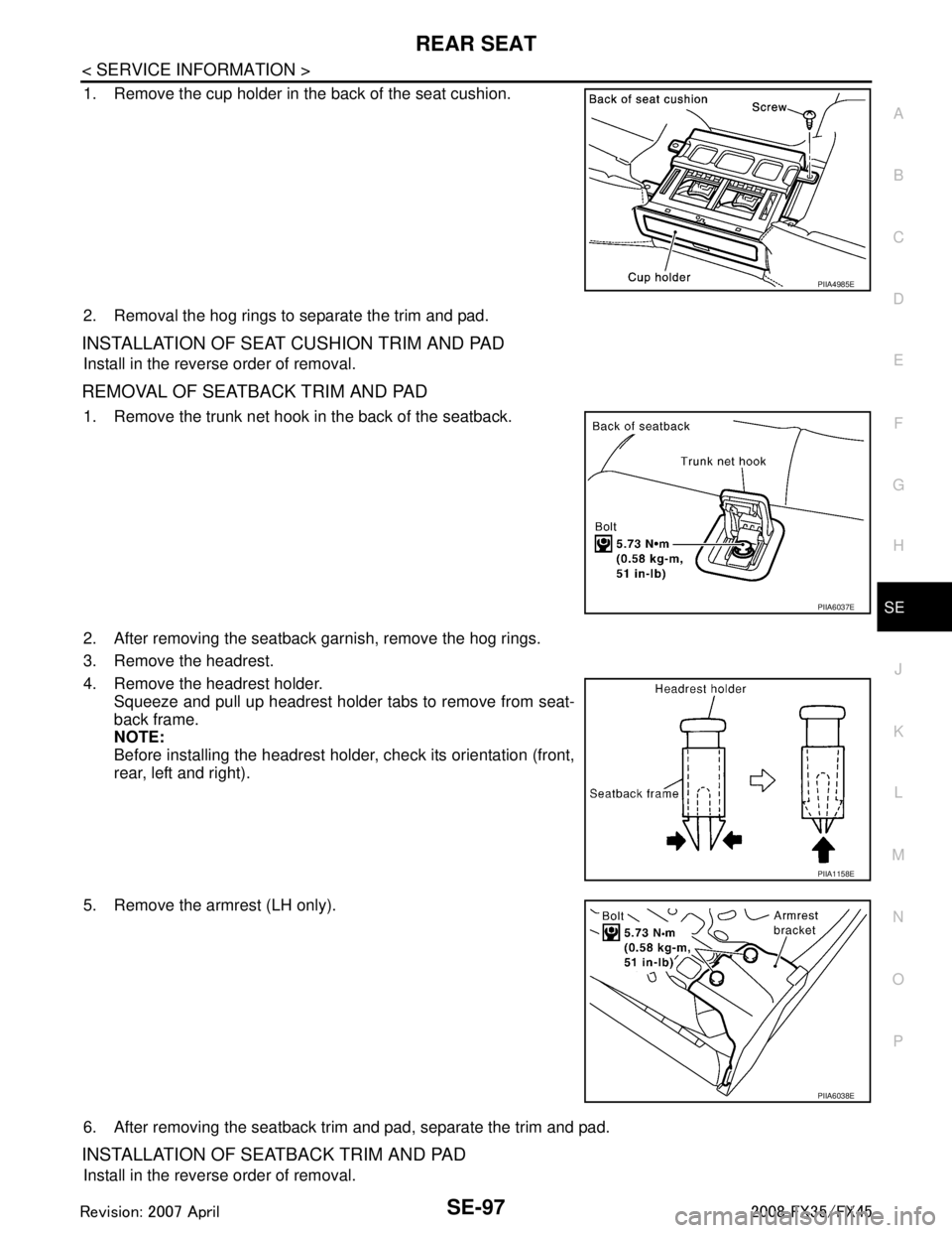
1. Remove the cup holder in the back of the seat cushion.
2. Removal the hog rings to separate the trim and pad.
INSTALLATION OF SEAT CUSHION TRIM AND PAD
Install in the reverse order of removal.
R E M O VA L O F S E AT B A C K T R I M A N D PA D
1. Remove the trunk net hook in the back of the seatback.
2. After removing the seatback garnish, remove the hog rings.
3. Remove the headrest.
4. Remove the headrest holder. Squeeze and pull up headrest holder tabs to remove from seat-
back frame.
NOTE:
Before installing the headrest holder, check its orientation (front,
rear, left and right).
5. Remove the armrest (LH only).
6. After removing the seatback trim and pad, separate the trim and pad.
INSTALLATION OF SEATBACK TRIM AND PAD
Install in the reverse order of removal.
PIIA4985E
PIIA6037E
PIIA1158E
PIIA6038E
3AA93ABC3ACD3AC03ACA3AC03AC63AC53A913A773A893A873A873A8E3A773A983AC73AC93AC03AC3
3A893A873A873A8F3A773A9D3AAF3A8A3A8C3A863A9D3AAF3A8B3A8C
Page 3737 of 3924

SE-98
< SERVICE INFORMATION >
REAR SEAT
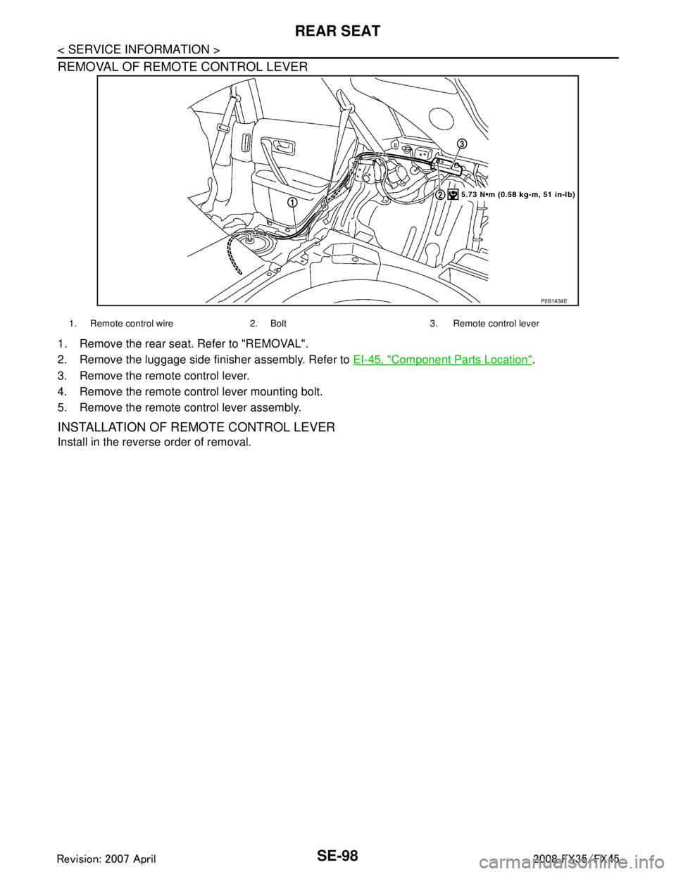
REMOVAL OF REMOTE CONTROL LEVER
1. Remove the rear seat. Refer to "REMOVAL".
2. Remove the luggage side finisher assembly. Refer to EI-45, "
Component Parts Location".
3. Remove the remote control lever.
4. Remove the remote control lever mounting bolt.
5. Remove the remote control lever assembly.
INSTALLATION OF REMOTE CONTROL LEVER
Install in the reverse order of removal.
PIIB1434E
1. Remote control wire 2. Bolt 3. Remote control lever
3AA93ABC3ACD3AC03ACA3AC03AC63AC53A913A773A893A873A873A8E3A773A983AC73AC93AC03AC3
3A893A873A873A8F3A773A9D3AAF3A8A3A8C3A863A9D3AAF3A8B3A8C
Page 3738 of 3924

SRS-1
RESTRAINTS
C
DE
F
G
I
J
K L
M
SECTION SRS
A
B
SRS
N
O P
CONTENTS
SUPPLEMENTAL RESTRAINT SYSTEM (SRS)
SERVICE INFORMATION .. ..........................2
DTC INDEX ..................................................... .....2
B1001-B1015 ...................................................... ......2
B1017-B1035 ............................................................2
B1042-B1057 ............................................................3
B1058-B1073 ............................................................3
B1074-B1089 ............................................................4
B1106-B1120 ............................................................4
B1122-B1137 ............................................................5
B1138-B1153 ............................................................5
B1202-B1210 ............................................................5
PRECAUTIONS ...................................................7
Precaution for Supplemental Restraint System
(SRS) "AIR BAG" and "SEAT BELT PRE-TEN-
SIONER" ............................................................. ......
7
Precaution for SRS "AIR BAG" and "SEAT BELT
PRE-TENSIONER" Service ......................................
7
Occupant Classification System Precaution .............7
PREPARATION ...................................................8
Commercial Service Tool .................................... ......8
SUPPLEMENTAL RESTRAINT SYSTEM
(SRS) ...................................................................
9
SRS Configuration .............................................. ......9
Front Seat Belt Pre-tensioner with Load Limiter .....10
Front Side Air Bag ...................................................10
Side Curtain Air Bag ................................................10
Occupant Classification System (OCS) ..................10
Passenger Air Bag Status Condition .......................11
Component Parts of Occupant Classification Sys-
tem ..........................................................................
11
TROUBLE DIAGNOSIS .....................................12
Trouble Diagnosis Introduction ........................... ....12
Component Parts Location ......................................14
Schematic ...............................................................15
Wiring Diagram - SRS - ...........................................16
CONSULT-III Function ........................................
....21
Self-Diagnosis Function (Without CONSULT-III) .....22
SRS Operation Check .............................................23
Trouble Diagnosis with CONSULT-III ......................24
Trouble Diagnosis without CONSULT-III .................28
Trouble Diagnosis: "AIR BAG" Warning Lamp
Does Not Turn OFF .................................................
32
Trouble Diagnosis: "AIR BAG" Warning Lamp
Does Not Turn ON ...................................................
32
DRIVER AIR BAG MODULE ............................34
Removal and Installation .........................................34
SPIRAL CABLE ................................................36
Removal and Installation .........................................36
FRONT PASSENGER AIR BAG MODULE ......38
Removal and Installation .........................................38
SIDE CURTAIN AIR BAG MODULE ................40
Removal and Installation .........................................40
CRASH ZONE SENSOR ...................................42
Removal and Installation ..................................... ....42
SIDE AIR BAG (SATELLITE) SENSOR ...........43
Removal and Installation .........................................43
DIAGNOSIS SENSOR UNIT .............................44
Removal and Installation .........................................44
FRONT SEAT BELT PRE-TENSIONER ...........45
Removal and Installation .........................................45
OCCUPANT CLASSIFICATION SYSTEM
CONTROL UNIT ................................................
46
Removal and Installation .........................................46
COLLISION DIAGNOSIS ..................................47
For Frontal Collision ................................................47
For Side Collision ....................................................48
3AA93ABC3ACD3AC03ACA3AC03AC63AC53A913A773A893A873A873A8E3A773A983AC73AC93AC03AC3
3A893A873A873A8F3A773A9D3AAF3A8A3A8C3A863A9D3AAF3A8B3A8C
Page 3739 of 3924

SRS-2
< SERVICE INFORMATION >
DTC INDEX
SERVICE INFORMATION
DTC INDEX
B1001-B1015INFOID:0000000001524145
B1017-B1035INFOID:0000000001524146
DTC Items (CONSULT screen terms) Reference
B1001
DIAGNOSIS SENSOR UNIT SRS-24, "
Trouble Diagnosis with CONSULT-III"
B1002
B1003
B1004
B1005
B1006
B1007
B1008
B1009
B1010
B1011
B1012
B1013
B1014
B1015
DTC Items (CONSULT sc reen terms) Reference
B1017 OCCUPANT SENSOR C/U
SRS-24, "
Trouble Diagnosis with CONSULT-III"
B1018 OCCUPANT SENS
B1019 BELT TENSION SENS
B1020OCCUPANT SENSOR C/U
B1021
B1022 OCCUPANT SENS C/U
B1023 PASS A/B INDCTR CKT
B1026
DIAGNOSIS SENSOR UNIT
B1027
B1028
B1029
B1030
B1031
B1033
CRASH ZONE SEN
B1034
B1035
3AA93ABC3ACD3AC03ACA3AC03AC63AC53A913A773A893A873A873A8E3A773A983AC73AC93AC03AC3
3A893A873A873A8F3A773A9D3AAF3A8A3A8C3A863A9D3AAF3A8B3A8C
Page 3740 of 3924

DTC INDEXSRS-3
< SERVICE INFORMATION >
C
DE
F
G
I
J
K L
M A
B
SRS
N
O P
B1042-B1057INFOID:0000000001524147
B1058-B1073INFOID:0000000001524148
DTC Items (CONSULT screen terms) Reference
B1042
DIAGNOSIS SENSOR UNIT
SRS-24, "
Trouble Diagnosis with CONSULT-III"
B1043
B1044
B1045
B1046
B1047
B1049DRIVER AIR BAG MODULE
B1050
B1051
B1052
B1054
B1055
B1056
B1057
DTC Items (CONSULT screen terms) Reference
B1058
DIAGNOSIS SENSOR UNIT
SRS-24, "
Trouble Diagnosis with CONSULT-III"
B1059
B1060
B1061
B1062
B1063
B1065ASSIST A/B MODULE
B1066
B1067
B1068
B1070
B1071
B1072
B1073
3AA93ABC3ACD3AC03ACA3AC03AC63AC53A913A773A893A873A873A8E3A773A983AC73AC93AC03AC3
3A893A873A873A8F3A773A9D3AAF3A8A3A8C3A863A9D3AAF3A8B3A8C