INFINITI FX35 2008 Service Manual
Manufacturer: INFINITI, Model Year: 2008, Model line: FX35, Model: INFINITI FX35 2008Pages: 3924, PDF Size: 81.37 MB
Page 3721 of 3924
SE-82
< SERVICE INFORMATION >
AUTOMATIC DRIVE POSITIONER
When voltage signal dose not appear with a constant voltage (approx. 5V), replace automatic
driver seat control unit.
When voltage signal dose not appear with a constant voltage (approx. 0V), replace driver seat
control unit.
4.CHECK DRIVER SEAT CONTROL UNIT
Dose the automatic drive positioner operate, when the driver seat control unit exchanged?
Does seat memory function operate?
YES >> Replace automatic drive positioner control unit.
NG >> Replace driver seat control unit.
Check Lumbar Support CircuitINFOID:0000000001328144
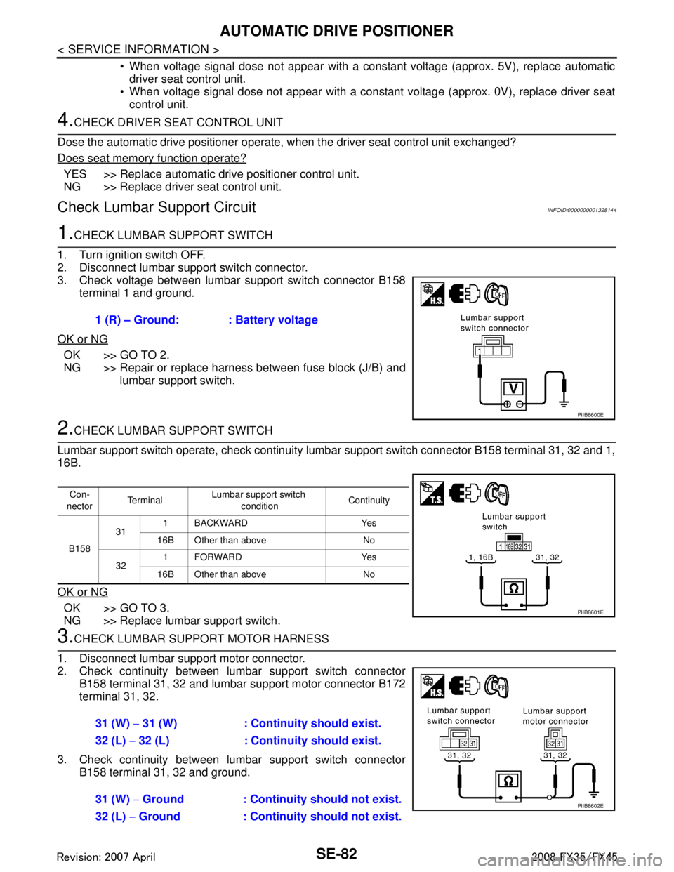
1.CHECK LUMBAR SUPPORT SWITCH
1. Turn ignition switch OFF.
2. Disconnect lumbar support switch connector.
3. Check voltage between lumbar support switch connector B158 terminal 1 and ground.
OK or NG
OK >> GO TO 2.
NG >> Repair or replace harness between fuse block (J/B) and lumbar support switch.
2.CHECK LUMBAR SUPPORT SWITCH
Lumbar support switch operate, check continuity lum bar support switch connector B158 terminal 31, 32 and 1,
16B.
OK or NG
OK >> GO TO 3.
NG >> Replace lumbar support switch.
3.CHECK LUMBAR SUPPORT MOTOR HARNESS
1. Disconnect lumbar support motor connector.
2. Check continuity between lumbar support switch connector B158 terminal 31, 32 and lumbar support motor connector B172
terminal 31, 32.
3. Check continuity between lumbar support switch connector B158 terminal 31, 32 and ground.1 (R) – Ground: : Battery voltage
PIIB8600E
Con-
nector Te r m i n a l
Lumbar support switch
condition Continuity
B158 31
1 BACKWARD Yes
16B Other than above No
32 1FORWARD Yes
16B Other than above No
PIIB8601E
31 (W) − 31 (W) : Continuity should exist.
32 (L) − 32 (L) : Continuity should exist.
31 (W) − Ground : Continuity should not exist.
32 (L) − Ground : Continuity should not exist.
PIIB8602E
3AA93ABC3ACD3AC03ACA3AC03AC63AC53A913A773A893A873A873A8E3A773A983AC73AC93AC03AC3
3A893A873A873A8F3A773A9D3AAF3A8A3A8C3A863A9D3AAF3A8B3A8C
Page 3722 of 3924
AUTOMATIC DRIVE POSITIONERSE-83
< SERVICE INFORMATION >
C
DE
F
G H
J
K L
M A
B
SE
N
O P
OK or NG
OK >> GO TO 4.
NG >> Repair or replace harness between lumbar support switch and lumbar support motor.
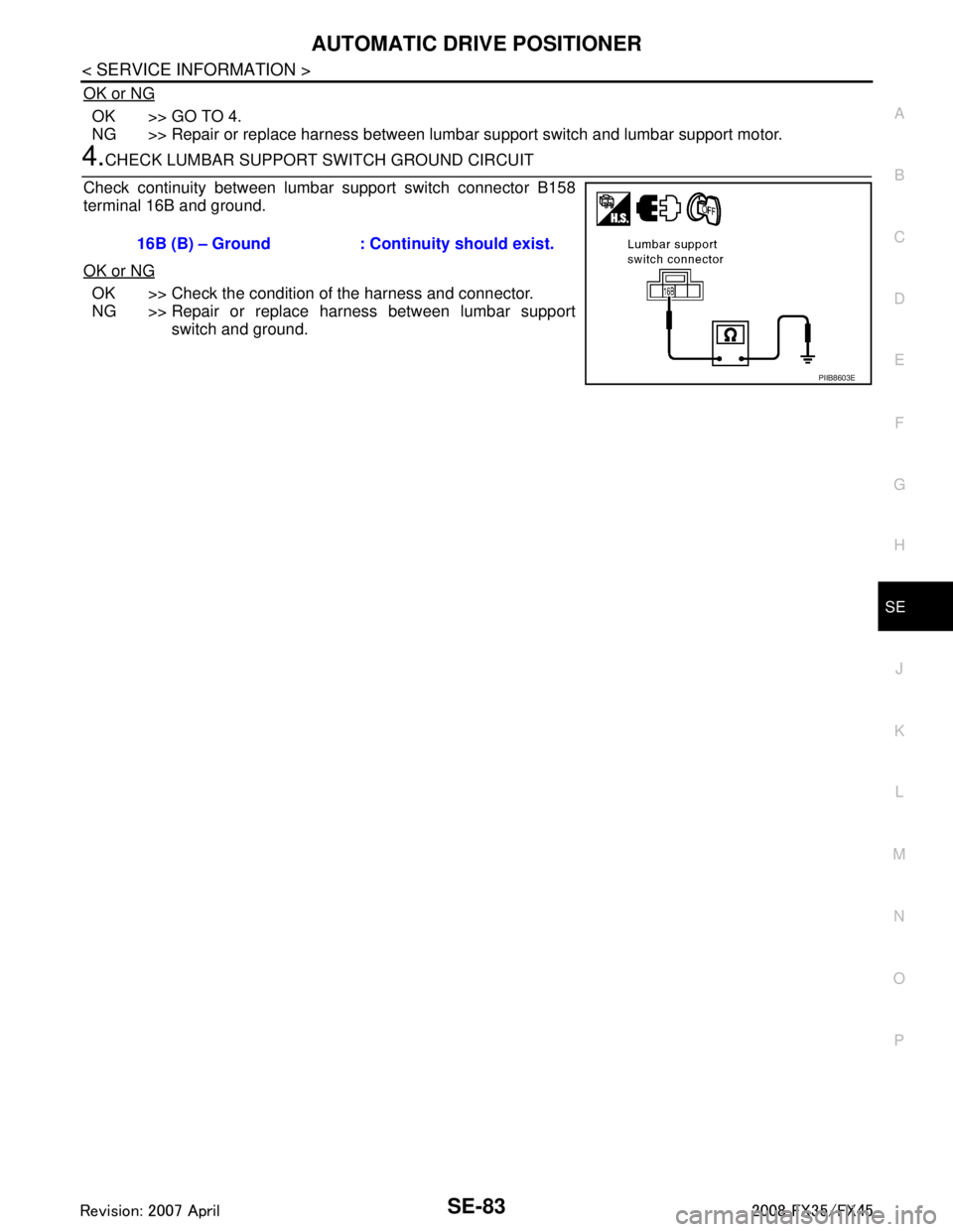
4.CHECK LUMBAR SUPPORT SWITCH GROUND CIRCUIT
Check continuity between lumbar support switch connector B158
terminal 16B and ground.
OK or NG
OK >> Check the condition of the harness and connector.
NG >> Repair or replace harness between lumbar support switch and ground.
16B (B) – Ground : Continuity should exist.
PIIB8603E
3AA93ABC3ACD3AC03ACA3AC03AC63AC53A913A773A893A873A873A8E3A773A983AC73AC93AC03AC3
3A893A873A873A8F3A773A9D3AAF3A8A3A8C3A863A9D3AAF3A8B3A8C
Page 3723 of 3924
SE-84
< SERVICE INFORMATION >
POWER SEAT
POWER SEAT
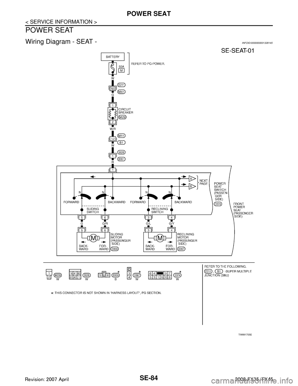
Wiring Diagram - SEAT -INFOID:0000000001328145
TIWM1705E
3AA93ABC3ACD3AC03ACA3AC03AC63AC53A913A773A893A873A873A8E3A773A983AC73AC93AC03AC3
3A893A873A873A8F3A773A9D3AAF3A8A3A8C3A863A9D3AAF3A8B3A8C
Page 3724 of 3924
POWER SEATSE-85
< SERVICE INFORMATION >
C
DE
F
G H
J
K L
M A
B
SE
N
O P
TIWM1717E
3AA93ABC3ACD3AC03ACA3AC03AC63AC53A913A773A893A873A873A8E3A773A983AC73AC93AC03AC3
3A893A873A873A8F3A773A9D3AAF3A8A3A8C3A863A9D3AAF3A8B3A8C
Page 3725 of 3924
SE-86
< SERVICE INFORMATION >
HEATED SEAT
HEATED SEAT
DescriptionINFOID:0000000001328146
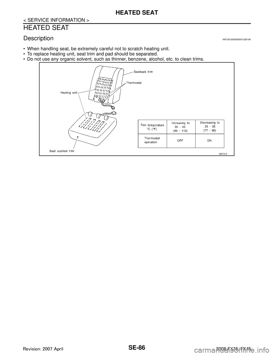
When handling seat, be extremely careful not to scratch heating unit.
To replace heating unit, seat trim and pad should be separated.
Do not use any organic solvent, such as thinner, benzene, alcohol, etc. to clean trims.
SBT314
3AA93ABC3ACD3AC03ACA3AC03AC63AC53A913A773A893A873A873A8E3A773A983AC73AC93AC03AC3
3A893A873A873A8F3A773A9D3AAF3A8A3A8C3A863A9D3AAF3A8B3A8C
Page 3726 of 3924
HEATED SEATSE-87
< SERVICE INFORMATION >
C
DE
F
G H
J
K L
M A
B
SE
N
O P
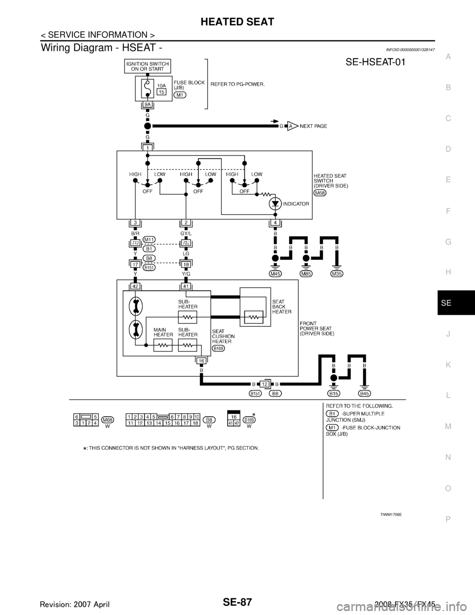
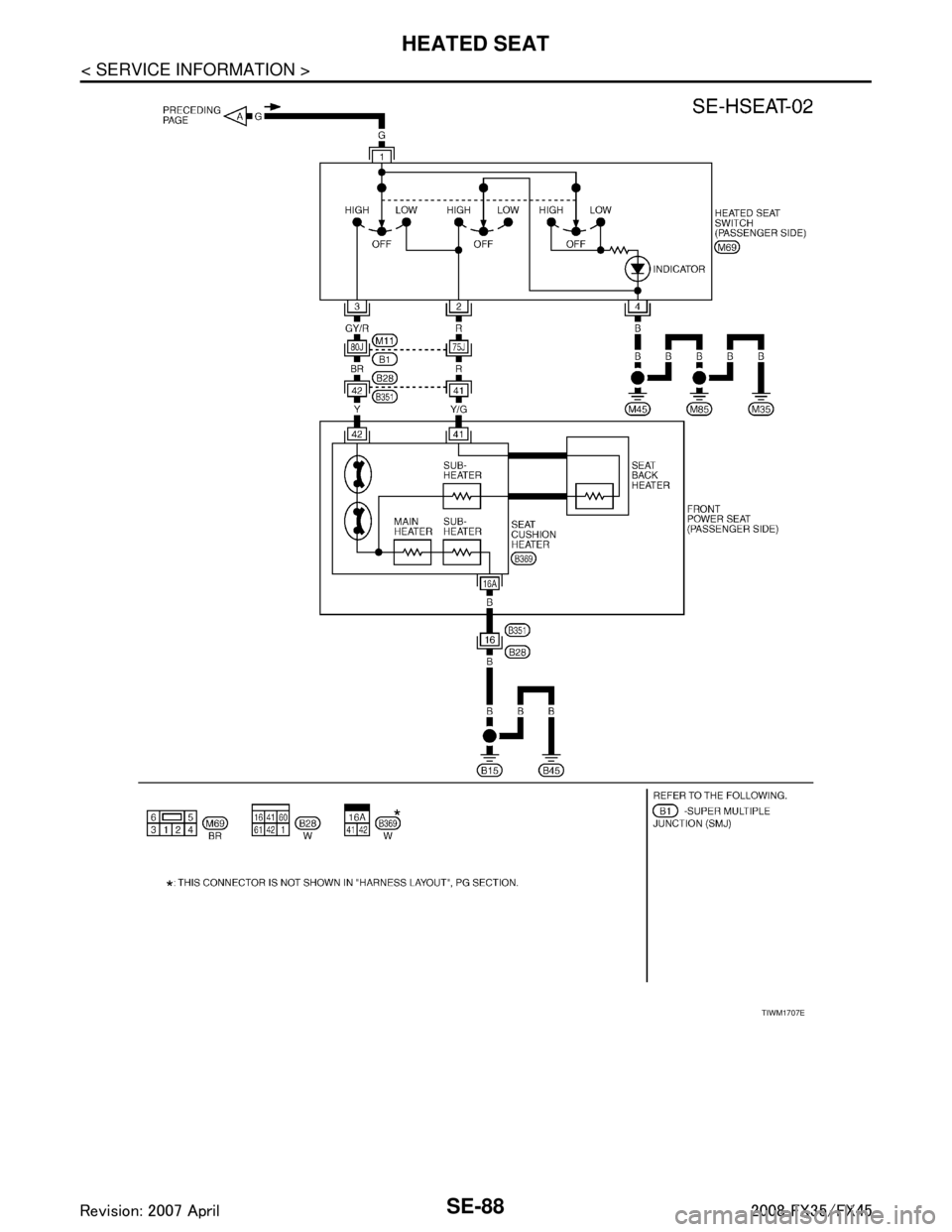
Wiring Diagram - HSEAT -INFOID:0000000001328147
TIWM1706E
3AA93ABC3ACD3AC03ACA3AC03AC63AC53A913A773A893A873A873A8E3A773A983AC73AC93AC03AC3
3A893A873A873A8F3A773A9D3AAF3A8A3A8C3A863A9D3AAF3A8B3A8C
Page 3727 of 3924
SE-88
< SERVICE INFORMATION >
HEATED SEAT
TIWM1707E
3AA93ABC3ACD3AC03ACA3AC03AC63AC53A913A773A893A873A873A8E3A773A983AC73AC93AC03AC3
3A893A873A873A8F3A773A9D3AAF3A8A3A8C3A863A9D3AAF3A8B3A8C
Page 3728 of 3924
FRONT SEATSE-89
< SERVICE INFORMATION >
C
DE
F
G H
J
K L
M A
B
SE
N
O P
FRONT SEAT
Removal and InstallationINFOID:0000000001328148
CAUTION:
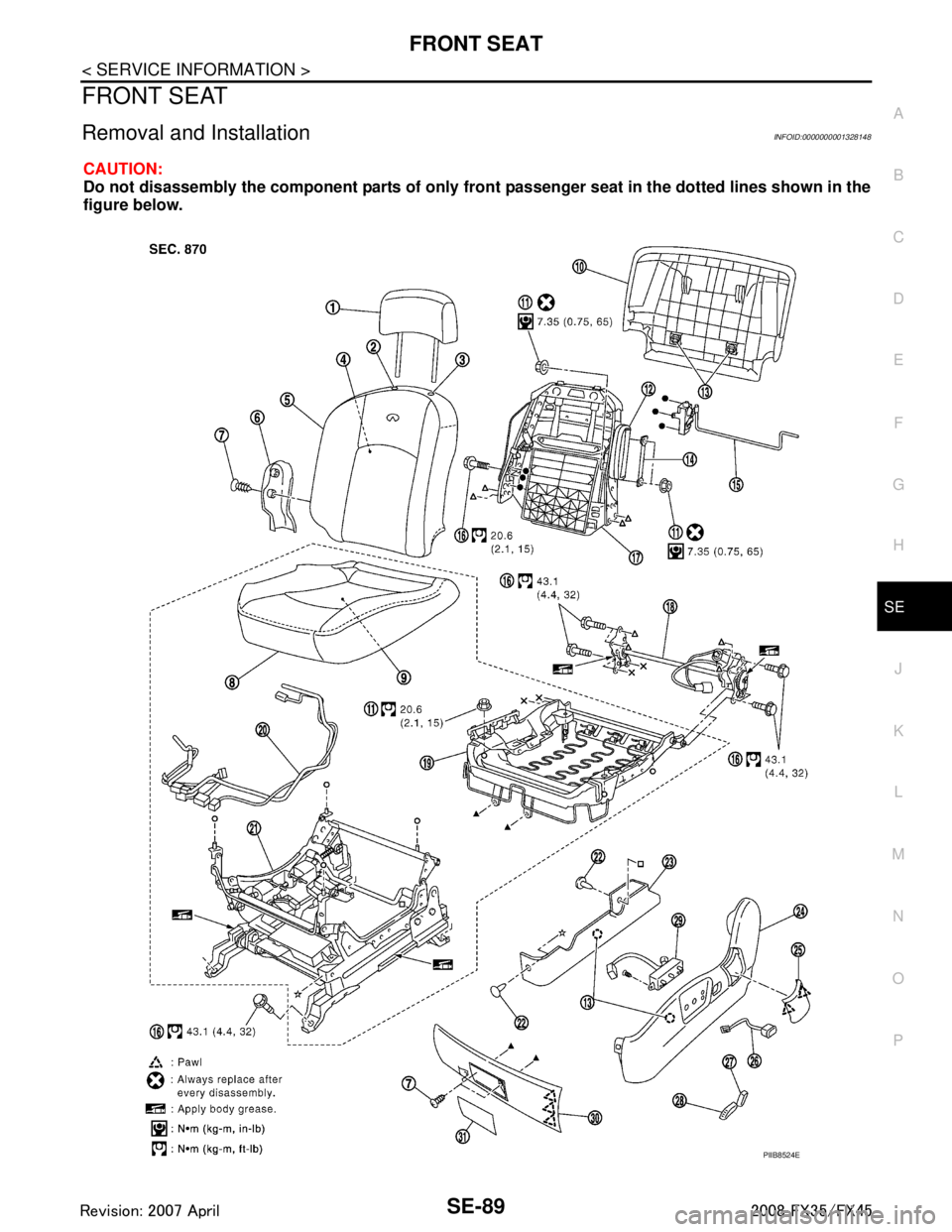
Do not disassembly the component parts of only fron t passenger seat in the dotted lines shown in the
figure below.
PIIB8524E
3AA93ABC3ACD3AC03ACA3AC03AC63AC53A913A773A893A873A873A8E3A773A983AC73AC93AC03AC3
3A893A873A873A8F3A773A9D3AAF3A8A3A8C3A863A9D3AAF3A8B3A8C
Page 3729 of 3924

SE-90
< SERVICE INFORMATION >
FRONT SEAT
REMOVAL
When removing or installing the seat trim, carefully handle it to keep dirt out and avoid damage.
CAUTION:
Before removing the front seat, turn ignition switch OFF, disconnect both battery cables and wait at
least 3 minutes.
When checking the power seat circuit for continuity using a circuit tester, do not confuse its connec-
tor with the side air bag modul e connector. Such an error may cause the air bag to deploy.
Do not drop, tilt, or bump the side air bag module installing in the seat. Always handle it with care.
1. Remove the seat cushion outer finisher cover.
2. Remove the front seat belt anchor bolt. Refer to SB-3, "
Removal
and Installation of Front Seat Belt".
CAUTION:
Set the front and rear cushion lifter to the down position.
3. Remove the screw.
4. Remove the seat cushion forward finisher lid.
5. Remove the seat cushion forward finisher.
6. Remove the seat slide and lifter switch knob (1) and seat reclin- ing switch knob (2).
1. Headrest 2. Headrest holder (free) 3. Headrest holder (locked)
4. Seatback pad 5. Seatback trim 6. Seat cushion inner finisher
7. Screw 8. Seat cushion trim 9. Seat cushion pad
10. Seatback garnish 11. Nut 12. Side air bag module
13. Clip (C101) 14. Inner cloth stay 15. Lumber support device
16. Bolt 17. Seatback frame 18. Reclining device assembly
19. Seat cushion frame 20. Seat harness assembly 21. Seat adjust assembly
22. Clip (C103) 23. Seat adjust assembly cover 24. Seat cushion outer finisher
25. Seat cushion outer finisher cover 26. Lumber support switch assembly 27. Seat reclining switch knob
28. Seat slide and lifter switch knob 29. Seat control switch 30. Seat cushion forward finisher
31. Seat cushion forward finisher lid
PIIA6040E
PIIB8525E
3AA93ABC3ACD3AC03ACA3AC03AC63AC53A913A773A893A873A873A8E3A773A983AC73AC93AC03AC3
3A893A873A873A8F3A773A9D3AAF3A8A3A8C3A863A9D3AAF3A8B3A8C
Page 3730 of 3924
FRONT SEATSE-91
< SERVICE INFORMATION >
C
DE
F
G H
J
K L
M A
B
SE
N
O P
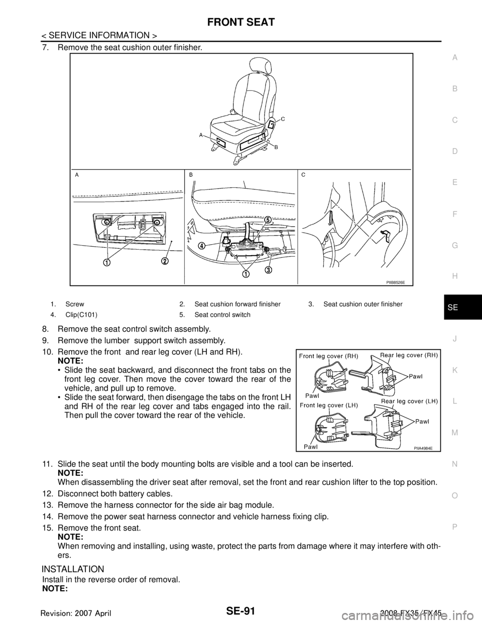
7. Remove the seat cushion outer finisher.
8. Remove the seat control switch assembly.
9. Remove the lumber support switch assembly.
10. Remove the front and rear leg cover (LH and RH). NOTE:
Slide the seat backward, and disconnect the front tabs on the
front leg cover. Then move the cover toward the rear of the
vehicle, and pull up to remove.
Slide the seat forward, then disengage the tabs on the front LH and RH of the rear leg cover and tabs engaged into the rail.
Then pull the cover toward the rear of the vehicle.
11. Slide the seat until the body mounting bolts are visible and a tool can be inserted. NOTE:
When disassembling the driver seat after removal, set the front and rear cushion lifter to the top position.
12. Disconnect both battery cables.
13. Remove the harness connector for the side air bag module.
14. Remove the power seat harness connector and vehicle harness fixing clip.
15. Remove the front seat. NOTE:
When removing and installing, using waste, protect t he parts from damage where it may interfere with oth-
ers.
INSTALLATION
Install in the reverse order of removal.
NOTE:
PIIB8526E
1. Screw 2. Seat cushion forward finisher 3. Seat cushion outer finisher
4. Clip(C101) 5. Seat control switch
PIIA4984E
3AA93ABC3ACD3AC03ACA3AC03AC63AC53A913A773A893A873A873A8E3A773A983AC73AC93AC03AC3
3A893A873A873A8F3A773A9D3AAF3A8A3A8C3A863A9D3AAF3A8B3A8C